wheel size Ram 3500 2020 Owner's Manual
[x] Cancel search | Manufacturer: RAM, Model Year: 2020, Model line: 3500, Model: Ram 3500 2020Pages: 568
Page 9 of 568

7
PARKSENSE REAR PARK ASSIST —
IF EQUIPPED ...................................................... 296 ParkSense Sensors ...................................296
ParkSense Warning Display ......................296
ParkSense Display ..................................... 297Enabling And Disabling ParkSense ..........299
Service The ParkSense Rear Park
Assist System .............................................299 Cleaning The ParkSense System ..............299
ParkSense System Usage Precautions ....299
PARKSENSE FRONT AND REAR
PARK ASSIST ..................................................... 301
ParkSense Sensors ...................................301
ParkSense Warning Display ......................301
ParkSense Display ..................................... 301Enabling And Disabling Front And/Or
Rear ParkSense .........................................304 Service The ParkSense Front/Rear
Park Assist System ....................................305 Cleaning The ParkSense System ..............305
ParkSense System Usage Precautions ....305
LANESENSE — IF EQUIPPED ........................... 306
LaneSense Operation ................................306Turning LaneSense On Or Off ...................307LaneSense Warning Message ..................307
Changing LaneSense Status .....................309 PARKVIEW REAR BACK UP CAMERA..............309
AUX Camera — If Equipped ...................... 311
SURROUND VIEW CAMERA SYSTEM —
IF EQUIPPED ....................................................... 312
AUX Camera — If Equipped ...................... 318
ENGINE RUNAWAY — DIESEL ENGINE ............ 319
REFUELING THE VEHICLE — GAS ENGINE ...... 319
Loose Fuel Filler Cap Message ................ 320
REFUELING THE VEHICLE — DIESEL ENGINE ... 320
Diesel Exhaust Fluid .................................. 321
VEHICLE LOADING ............................................324
Gross Vehicle Weight Rating (GVWR) ...... 324
Payload ....................................................... 324Gross Axle Weight Rating (GAWR) ............ 324
Tire Size ...................................................... 324
Rim Size ..................................................... 324
Inflation Pressure ...................................... 324
Curb Weight................................................ 324
Loading ....................................................... 324
TRAILER TOWING ............................................... 325
Common Towing Definitions ..................... 325Trailer Hitch Type and Maximum
Trailer Weight ............................................. 329 Trailer Towing Weights (Maximum Trailer
Weight Ratings) ......................................... 330 Trailer And Tongue Weight ........................ 330
Towing Requirements ............................... 330Towing Tips ................................................ 335 SNOWPLOW ...................................................... 336
Before Plowing ........................................... 337
Snowplow Prep Package Model
Availability .................................................. 337 Over The Road Operation With
Snowplow Attached ................................... 338 Operating Tips............................................ 338General Maintenance................................ 338
RECREATIONAL TOWING (BEHIND
MOTORHOME, ETC.) ......................................... 339
Towing This Vehicle Behind Another
Vehicle ........................................................ 339 Recreational Towing — Two-Wheel Drive
Models........................................................ 339 Recreational Towing — Four-Wheel Drive
Models........................................................ 340
DRIVING TIPS ..................................................... 343
Driving On Slippery Surfaces ................... 343
Driving Through Water ............................. 343
Off-Road Driving Tips ................................. 344
IN CASE OF EMERGENCY
HAZARD WARNING FLASHERS ...................... 346
ASSIST AND SOS SYSTEM — IF EQUIPPED .... 346General Information .................................. 350
20_DJD2_OM_EN_USC_t.book Page 7
Page 138 of 568
136GETTING TO KNOW YOUR INSTRUMENT PANEL
Trailer Merge Assist Indicator Light — If
Equipped
This indicator light will illuminate to
indicate when Trailer Merge Assist
has been activated.
Refer to “Blind Spot Monitoring (BSM)” in
“Safety” for further information.
Tire Pressure Monitoring System (TPMS)
Warning Light
The warning light switches on and a
message is displayed to indicate that
the tire pressure is lower than the
recommended value and/or that slow
pressure loss is occurring. In these cases,
optimal tire duration and fuel consumption may
not be guaranteed.
Should one or more tires be in the condition
mentioned above, the display will show the
indications corresponding to each tire. Each tire, including the spare (if provided),
should be checked monthly when cold and
inflated to the inflation pressure recommended
by the vehicle manufacturer on the vehicle
placard or tire inflation pressure label. If your
vehicle has tires of a different size than the size
indicated on the vehicle placard or tire inflation
pressure label, you should determine the
proper tire inflation pressure for those tires.
As an added safety feature, your vehicle has
been equipped with a Tire Pressure Monitoring
System (TPMS) that illuminates a low tire
pressure telltale when one or more of your tires
is significantly under-inflated. Accordingly, when
the low tire pressure telltale illuminates, you
should stop and check your tires as soon as
possible, and inflate them to the proper
pressure. Driving on a significantly
under-inflated tire causes the tire to overheat
and can lead to tire failure. Under-inflation also
reduces fuel efficiency and tire tread life, and
may affect the vehicle’s handling and stopping
ability.
Please note that the TPMS is not a substitute for
proper tire maintenance, and it is the driver’s
responsibility to maintain correct tire pressure, even if under-inflation has not reached the level
to trigger illumination of the TPMS low tire
pressure telltale.
Your vehicle has also been equipped with a
TPMS malfunction indicator to indicate when
the system is not operating properly. The TPMS
malfunction indicator is combined with the low
tire pressure telltale. When the system detects
a malfunction, the telltale will flash for
approximately one minute and then remain
continuously illuminated. This sequence will
continue upon subsequent vehicle start-ups as
long as the malfunction exists. When the
malfunction indicator is illuminated, the system
may not be able to detect or signal low tire
pressure as intended. TPMS malfunctions may
occur for a variety of reasons, including the
installation of replacement or alternate tires or
wheels on the vehicle that prevent the TPMS
from functioning properly. Always check the
TPMS malfunction telltale after replacing one or
more tires or wheels on your vehicle to ensure
that the replacement or alternate tires and
wheels allow the TPMS to continue to function
properly.
CAUTION!
Do not continue driving with one or more flat
tires as handling may be compromised. Stop the
vehicle, avoiding sharp braking and steering. If a
tire puncture occurs, repair immediately using
the dedicated tire repair kit and contact an
authorized dealer as soon as possible.
20_DJD2_OM_EN_USC_t.book Page 136
Page 139 of 568
GETTING TO KNOW YOUR INSTRUMENT PANEL137
Anti-Lock Brake System(ABS) Warning
Light
This warning light monitors the
Anti-Lock Brake System (ABS). The
light will turn on when the ignition is
placed in the ON/RUN or ACC/ON/
RUN position and may stay on for as long as
four seconds.
If the ABS light remains on or turns on while
driving, then the Anti-Lock portion of the brake system is not functioning and service is
required as soon as possible. However, the
conventional brake system will continue to
operate normally, assuming the Brake Warning
Light is not also on.
If the ABS light does not turn on when the
ignition is placed in the ON/RUN or ACC/ON/
RUN position, have the brake system inspected
by an authorized dealer.
Rear Axle Locker Fault Indicator Light — If
Equipped
This warning light will illuminate to
indicate when a rear axle locker fault
has been detected.
Refer to “Axle Locker System — Power Wagon
Models Only (If Equipped)” in “Starting And
Operating” for further information.
Service Forward Collision Warning (FCW)
Light — If Equipped
This warning light will illuminate to
indicate a fault in the Forward
Collision Warning System. Contact an
authorized dealer for service.
Refer to "Forward Collision Warning (FCW)" in
"Safety" for further information.
Service 4WD Warning Light — If Equipped
This warning light will illuminate to
signal a fault with the 4WD system. If
the light stays on or comes on during
driving, it means that the 4WD system
is not functioning properly and that service is
required. We recommend you drive to the
nearest service center and have the vehicle
serviced immediately.
Speed Control Fault Warning Light
This warning light will illuminate to
indicate the Speed Control System is
not functioning properly and service is
required. Contact an authorized dealer.
Sway Bar Fault Warning Light
This light will illuminate when there is
a fault in the sway bar disconnect
system.
Refer to “Stabilizer/Sway Bar System — Power
Wagon Only” in “Starting And Operating” for
further information.
CAUTION!
The TPMS has been optimized for the original
equipment tires and wheels. TPMS pressures
and warning have been established for the
tire size equipped on your vehicle.
Undesirable system operation or sensor
damage may result when using replacement
equipment that is not of the same size, type,
and/or style. Aftermarket wheels can cause
sensor damage. Using aftermarket tire
sealants may cause the Tire Pressure
Monitoring System (TPMS) sensor to become
inoperable. After using an aftermarket tire
sealant it is recommended that you take your
vehicle to an authorized dealer to have your
sensor function checked.
3
20_DJD2_OM_EN_USC_t.book Page 137
Page 149 of 568
SAFETY147
ESC Operating Modes
NOTE:
Depending upon model and mode of operation,
the ESC system may have multiple operating
modes. ESC On
This is the normal operating mode for the ESC.
Whenever the vehicle is started, the ESC system
will be in this mode. This mode should be used
for most driving conditions. Alternate ESC
modes should only be used for specific reasons
as noted in the following paragraphs.
Partial Off
The “Partial Off” mode is intended for times
when a more spirited driving experience is
desired. This mode may modify TCS and ESC
thresholds for activation, which allows for more
wheel spin than normally allowed. This mode
may be useful if the vehicle becomes stuck.
To enter the “Partial Off” mode, momentarily
push the “ESC OFF” switch and the “ESC OFF
Indicator Light” will illuminate. To turn the ESC
on again, momentarily push the “ESC OFF”
switch and the “ESC OFF Indicator Light” will
turn off.
NOTE:
For vehicles with multiple partial ESC modes, a
momentary button push will toggle the ESC
mode. Multiple momentary button pushes may
be required to return to ESC On.
Vehicle modifications, or failure to properly
maintain your vehicle, may change the
handling characteristics of your vehicle,
and may negatively affect the performance
of the ESC system. Changes to the steering
system, suspension, braking system, tire
type and size or wheel size may adversely
affect ESC performance. Improperly
inflated and unevenly worn tires may also
degrade ESC performance. Any vehicle
modification or poor vehicle maintenance
that reduces the effectiveness of the ESC
system can increase the risk of loss of
vehicle control, vehicle rollover, personal
injury and death.
WARNING!
(Continued)
WARNING!
When in “Partial Off” mode, the TCS func -
tionality of ESC, (except for the limited slip
feature described in the TCS section), has
been disabled and the “ESC Off Indicator
Light” will be illuminated. When in “Partial
Off” mode, the engine power reduction
feature of TCS is disabled, and the
enhanced vehicle stability offered by the
ESC system is reduced.
Trailer Sway Control (TSC) is disabled when
the ESC system is in the “Partial Off” mode.
4
20_DJD2_OM_EN_USC_t.book Page 147
Page 160 of 568
158SAFETY
NOTE:
When a trailer with an electric brake is
connected to the vehicle, the instrument cluster
display will provide a menu to allow a selection
of the trailer type. There will be two options
provided: Conventional and Goose/Fifth Wheel.
Goose/Fifth Wheel Trailer is incompatible and
when selected, the BSM system will disable
until the trailer is disconnected. If the wrong
option is selected, the system can be reset by
either disconnecting and reconnecting the
trailer harness connector or disabling then
re-enabling the Blind Spot Monitoring System in
the customer settings in the Uconnect. This will
prompt the trailer selection menu again to allow
for the correct selection.
Trailer Merge Assist is a function of the Blind
Spot Monitoring (BSM) system that extends the
blind spot zone to work while pulling a trailer.
Trailer Merge Assist consists of three sub
functions:
Automatic Trailer Detection
Trailer Length Detection
Trailer Merge Warning
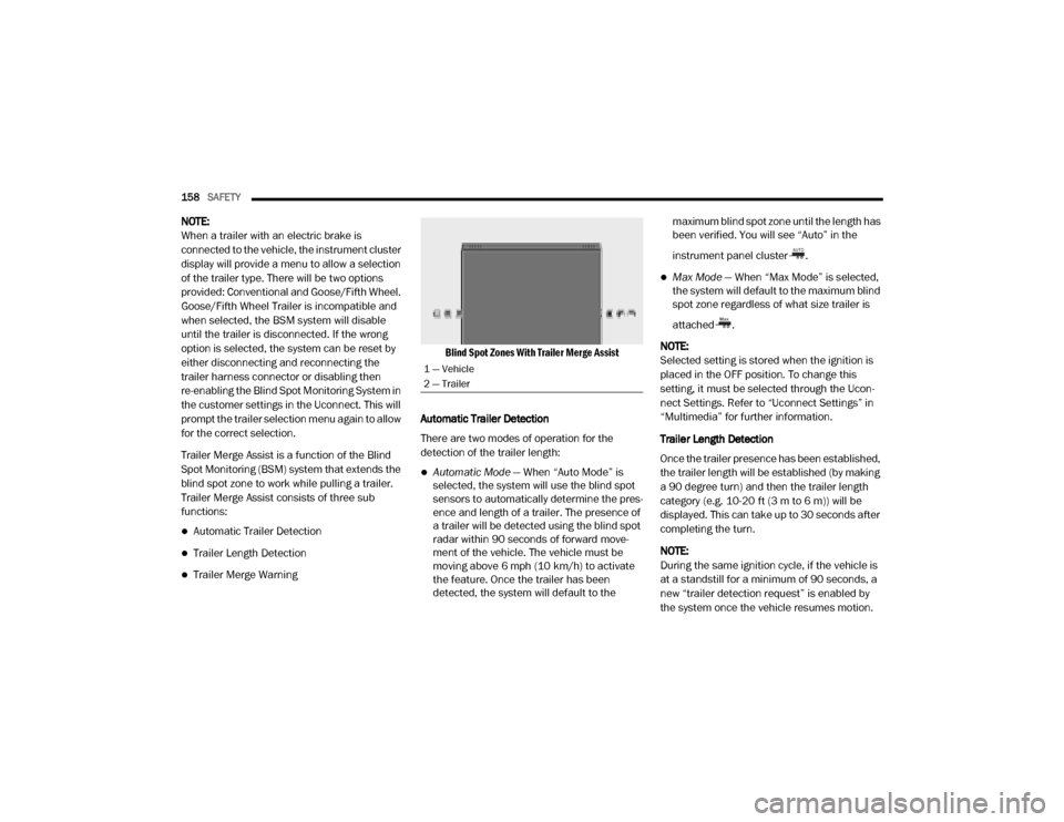
Blind Spot Zones With Trailer Merge Assist
Automatic Trailer Detection
There are two modes of operation for the
detection of the trailer length:
Automatic Mode — When “Auto Mode” is
selected, the system will use the blind spot
sensors to automatically determine the pres -
ence and length of a trailer. The presence of
a trailer will be detected using the blind spot
radar within 90 seconds of forward move -
ment of the vehicle. The vehicle must be
moving above 6 mph (10 km/h) to activate the feature. Once the trailer has been
detected, the system will default to the maximum blind spot zone until the length has
been verified. You will see “Auto” in the
instrument panel cluster .
Max Mode
— When “Max Mode” is selected,
the system will default to the maximum blind
spot zone regardless of what size trailer is
attached .
NOTE:
Selected setting is stored when the ignition is
placed in the OFF position. To change this
setting, it must be selected through the Ucon -
nect Settings. Refer to “Uconnect Settings” in
“Multimedia” for further information.
Trailer Length Detection
Once the trailer presence has been established,
the trailer length will be established (by making
a 90 degree turn) and then the trailer length
category (e.g. 10-20 ft (3 m to 6 m)) will be
displayed. This can take up to 30 seconds after
completing the turn.
NOTE:
During the same ignition cycle, if the vehicle is
at a standstill for a minimum of 90 seconds, a
new “trailer detection request” is enabled by
the system once the vehicle resumes motion.
1 — Vehicle
2 — Trailer
20_DJD2_OM_EN_USC_t.book Page 158
Page 161 of 568
SAFETY159
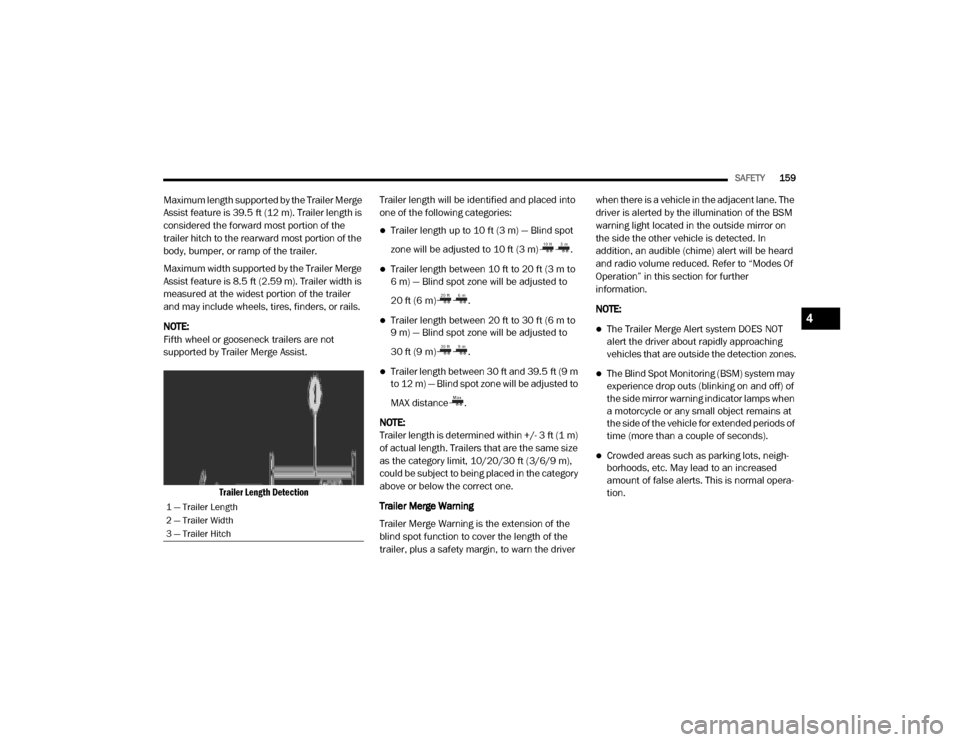
Maximum length supported by the Trailer Merge
Assist feature is 39.5 ft (12 m). Trailer length is
considered the forward most portion of the
trailer hitch to the rearward most portion of the
body, bumper, or ramp of the trailer.
Maximum width supported by the Trailer Merge
Assist feature is 8.5 ft (2.59 m). Trailer width is
measured at the widest portion of the trailer
and may include wheels, tires, finders, or rails.
NOTE:
Fifth wheel or gooseneck trailers are not
supported by Trailer Merge Assist.
Trailer Length Detection
Trailer length will be identified and placed into
one of the following categories:
Trailer length up to 10 ft (3 m) — Blind spot
zone will be adjusted to 10 ft (3 m) .
Trailer length between 10 ft to 20 ft (3 m to
6 m) — Blind spot zone will be adjusted to
20 ft (6 m) .
Trailer length between 20 ft to 30 ft (6 m to
9 m) — Blind spot zone will be adjusted to
30 ft (9 m) .
Trailer length between 30 ft and 39.5 ft (9 m
to 12 m) — Blind spot zone will be adjusted to
MAX distance .
NOTE:
Trailer length is determined within +/- 3 ft (1 m)
of actual length. Trailers that are the same size
as the category limit, 10/20/30 ft (3/6/9 m),
could be subject to being placed in the category
above or below the correct one.
Trailer Merge Warning
Trailer Merge Warning is the extension of the
blind spot function to cover the length of the
trailer, plus a safety margin, to warn the driver when there is a vehicle in the adjacent lane. The
driver is alerted by the illumination of the BSM
warning light located in the outside mirror on
the side the other vehicle is detected. In
addition, an audible (chime) alert will be heard
and radio volume reduced. Refer to “Modes Of
Operation” in this section for further
information.
NOTE:
The Trailer Merge Alert system DOES NOT
alert the driver about rapidly approaching
vehicles that are outside the detection zones.
The Blind Spot Monitoring (BSM) system may
experience drop outs (blinking on and off) of
the side mirror warning indicator lamps when
a motorcycle or any small object remains at
the side of the vehicle for extended periods of
time (more than a couple of seconds).
Crowded areas such as parking lots, neigh
-
borhoods, etc. May lead to an increased
amount of false alerts. This is normal opera -
tion.
1 — Trailer Length
2 — Trailer Width
3 — Trailer Hitch
4
20_DJD2_OM_EN_USC_t.book Page 159
Page 166 of 568

164SAFETY
1 mile (1.6 km) after a three hour period. The
cold tire inflation pressure must not exceed the
maximum inflation pressure molded into the
tire sidewall. Refer to “Tires” in “Servicing And
Maintenance” for information on how to
properly inflate the vehicle’s tires. The tire
pressure will also increase as the vehicle is
driven - this is normal and there should be no
adjustment for this increased pressure.
The TPMS will warn the driver of a low tire
pressure if the tire pressure falls below the
low-pressure warning limit for any reason,
including low temperature effects and natural
pressure loss through the tire.
The TPMS will continue to warn the driver of low
tire pressure as long as the condition exists,
and will not turn off until the tire pressure is at
or above the recommended cold placard
pressure. Once the low TPMS Warning Light
illuminates, you must increase the tire pressure
to the recommended cold placard pressure in
order for the TPMS Warning Light to turn off. The
system will automatically update and the TPMS
Warning Light will turn off once the system
receives the updated tire pressures. The vehicle may need to be driven for up to 20 minutes
above 15 mph (24 km/h) in order for the TPMS
to receive this information.
NOTE:
When filling warm tires, the tire pressure may
need to be increased up to an additional 4 psi
(28 kPa) above the recommended cold placard
pressure in order to turn the TPMS Warning
Light off.
For example, your vehicle may have a
recommended cold (parked for more than three
hours) placard pressure of 30 psi (207 kPa). If
the ambient temperature is 68°F (20°C) and the
measured tire pressure is 27 psi (186 kPa), a
temperature drop to 20°F (-7°C) will decrease
the tire pressure to approximately 23 psi
(158 kPa). This tire pressure is sufficiently low
enough to turn on the TPMS Warning Light.
Driving the vehicle may cause the tire pressure to
rise to approximately 27 psi (186 kPa), but the
TPMS Warning Light will still be on. In this
situation, the TPMS Warning Light will turn off
only after the tires are inflated to the vehicle’s
recommended cold placard pressure value.
CAUTION!
The TPMS has been optimized for the orig -
inal equipment tires and wheels. TPMS
pressures and warning have been estab -
lished for the tire size equipped on your
vehicle. Undesirable system operation or
sensor damage may result when using
replacement equipment that is not of the
same size, type, and/or style. Aftermarket
wheels can cause sensor damage.
Using aftermarket tire sealants may cause
the Tire Pressure Monitoring System
(TPMS) sensor to become inoperable. After
using an aftermarket tire sealant it is
recommended that you take your vehicle to
an authorized dealership to have your
sensor function checked.
After inspecting or adjusting the tire pres -
sure always reinstall the valve stem cap.
This will prevent moisture and dirt from
entering the valve stem, which could
damage the TPMS sensor.
20_DJD2_OM_EN_USC_t.book Page 164
Page 168 of 568

166SAFETY
Should this occur, you should stop as soon as
possible and inflate the tires with a low pressure
condition (those in a different color in the
instrument cluster graphic) to the vehicle’s
recommended cold placard pressure inflation
value as shown in the "Inflate to XX" message.
Once the system receives the updated tire
pressures, the system will automatically
update, the graphic display in the instrument
cluster will return to its original color, and the
“Tire Pressure Monitoring Telltale Light” will
turn off. The vehicle may need to be driven for
up to 20 minutes above 15 mph (24 km/h) in
order for the TPMS to receive this information.
NOTE:
When filling warm tires, the tire pressure may
need to be increased up to an additional 4 psi
(28 kPa) above the recommended cold placard
pressure in order to turn the Tire Pressure Moni -
toring Warning Light off.
Service TPMS Warning
If a system fault is detected, the “Tire Pressure
Monitoring Warning Light” will flash on and off
for 75 seconds and then remain on solid. In
addition, the instrument cluster will display a "SERVICE TPM SYSTEM" message for a
minimum of five seconds and then display
dashes (- -) in place of the pressure value to
indicate which sensor is not being received.
If the ignition switch is cycled, this sequence will
repeat, providing the system fault still exists. If
the system fault no longer exists, the “Tire
Pressure Monitoring Warning Light” will no
longer flash, and the "SERVICE TPM SYSTEM"
message will no longer display, and a pressure
value will display in place of the dashes. A
system fault can occur due to any of the
following:
Signal interference due to electronic devices
or driving next to facilities emitting the same
radio frequencies as the TPM sensors.
Installing aftermarket window tinting that
contains materials that may block radio wave
signals.
Accumulation of snow or ice around the
wheels or wheel housings.
Using tire chains on the vehicle.
Using wheels/tires not equipped with TPM
sensors.A system fault may occur due to an incorrect
TPM sensor location condition. When a system
fault occurs due to an incorrect TPM sensor
location, the “Tire Pressure Monitoring Warning
Light” will flash on and off for 75 seconds and
then remain on solid. The system fault will also
sound a chime. In addition, the instrument
cluster will display a “Tire Pressure Temporarily
Unavailable” message in place of the tire
pressure display screen. If the ignition switch is
cycled, this sequence will repeat, providing the
system fault still exists. If the system fault no
longer exists, the “Tire Pressure Monitoring
Warning Light” will no longer flash and the tire
pressure display screen will be displayed
showing the tire pressure values the correct
locations.
Vehicles With Non-Matching Full Size Spare Or
Compact Spare
The non-matching full size spare or compact
spare tire does not have a TPM sensor.
Therefore, the TPMS will not monitor the
pressure in the non-matching full size spare
or compact spare tire.
20_DJD2_OM_EN_USC_t.book Page 166
Page 187 of 568
SAFETY185
Front Air Bag Operation
Front Air Bags are designed to provide
additional protection by supplementing the seat
belts. Front air bags are not expected to reduce
the risk of injury in rear, side, or rollover
collisions. The front air bags will not deploy in all
frontal collisions, including some that may
produce substantial vehicle damage — for
example, some pole collisions, truck
underrides, and angle offset collisions.
On the other hand, depending on the type and
location of impact, front air bags may deploy in
crashes with little vehicle front-end damage but
that produce a severe initial deceleration. Because air bag sensors measure vehicle
deceleration over time, vehicle speed and
damage by themselves are not good indicators
of whether or not an air bag should have
deployed.
Seat belts are necessary for your protection in
all collisions, and also are needed to help keep
you in position, away from an inflating air bag.
When the ORC detects a collision requiring the
front air bags, it signals the inflator units. A large
quantity of non-toxic gas is generated to inflate
the front air bags.
The steering wheel hub trim cover and the
upper passenger side of the instrument panel
separate and fold out of the way as the air bags
inflate to their full size. The front air bags fully
inflate in less time than it takes to blink your
eyes. The front air bags then quickly deflate
while helping to restrain the driver and front
passenger.
Knee Impact Bolsters
The Knee Impact Bolsters help protect the
knees of the driver and front passenger, and
position the front occupants for improved
interaction with the front air bags.
Supplemental Side Air Bags
Supplemental Seat-Mounted Side Air Bags
(SABs)
This vehicle is equipped with Supplemental
Seat-Mounted Side Air Bags (SABs).
Supplemental Seat-Mounted Side Air Bags
(SABs) are located in the outboard side of the
front seats. The SABs are marked with “SRS
AIRBAG” or “AIRBAG” on a label or on the seat
trim on the outboard side of the seats.
Relying on the air bags alone could lead to
more severe injuries in a collision. The air
bags work with your seat belt to restrain you
properly. In some collisions, air bags won’t
deploy at all. Always wear your seat belts
even though you have air bags.
WARNING!
(Continued)
WARNING!
Do not drill, cut, or tamper with the knee
impact bolsters in any way.
Do not mount any accessories to the knee
impact bolsters such as alarm lights,
stereos, citizen band radios, etc.4
20_DJD2_OM_EN_USC_t.book Page 185
Page 250 of 568
248STARTING AND OPERATING
NOTE:
The transfer case NEUTRAL button is located in
the center of the 4WD Control Switch and is
pushed by using a ballpoint pen or similar
object. The transfer case NEUTRAL position is to
be used for recreational towing only. Refer to
“Recreational Towing” in “Starting And Oper -
ating” for further information.
Transfer Case Position Indicator Lights
The Transfer Case Position Indicator Lights
(4WD HIGH and 4WD LOW) are located in the
instrument cluster and indicate the current and
desired transfer case selection. When you
select a different transfer case position, the
indicator lights will do the following:
If All Of The Following Shift Conditions Are Met:
1. The current position indicator light will turn off.
2. The selected position indicator light will flash until the transfer case completes the
shift.
3. When the shift is complete, the indicator light for the selected position will stop
flashing and remain on. If One Or More Of The Following Shift Conditions
Are Not Met:
1. The indicator light for the current position
will remain on.
2. The newly selected position indicator light will continue to flash.
3. The transfer case will not shift.
NOTE:
Before retrying a selection, make certain that all
the necessary requirements for selecting a new
transfer case position have been met. To retry the
selection, push the current position, wait five
seconds, and retry selection. To find the shift
requirements, refer to the “Shifting Procedure”
for your transfer case, located in this section.
The “SVC 4WD Warning Light” monitors the
electronic shift four-wheel drive system. If this
light remains on after engine start up or
illuminates during driving, it means that the
four-wheel drive system is not functioning
properly and that service is required.
NOTE:
Do not attempt to make a shift while only the
front or rear wheels are spinning. This could
cause damage to driveline components. When operating your vehicle in 4WD LOW, the
engine speed is approximately three times that
of the 2WD or 4WD HIGH positions at a given
road speed. Take care not to overspeed the
engine and do not exceed 25 mph (40 km/h).
Proper operation of four-wheel drive vehicles
depends on tires of equal size, type and
circumference on each wheel. Any difference in
tire size can cause damage to the drivetrain.
Because four-wheel drive provides improved
traction, there is a tendency to exceed safe
turning and stopping speeds. Do not go faster
than road conditions permit.
Shifting Procedure
NOTE:
If any of the requirements to select a new
transfer case position have not been met, the
transfer case will not shift. The position indi
-
cator light for the previous position will
remain on and the newly selected position
indicator light will continue to flash until all
the requirements for the selected position
have been met.
If all the requirements to select a new
transfer case position have been met, the
20_DJD2_OM_EN_USC_t.book Page 248