mirror Ram 3500 Chassis Cab 2020 User Guide
[x] Cancel search | Manufacturer: RAM, Model Year: 2020, Model line: 3500 Chassis Cab, Model: Ram 3500 Chassis Cab 2020Pages: 516, PDF Size: 29.24 MB
Page 60 of 516

58GETTING TO KNOW YOUR VEHICLE
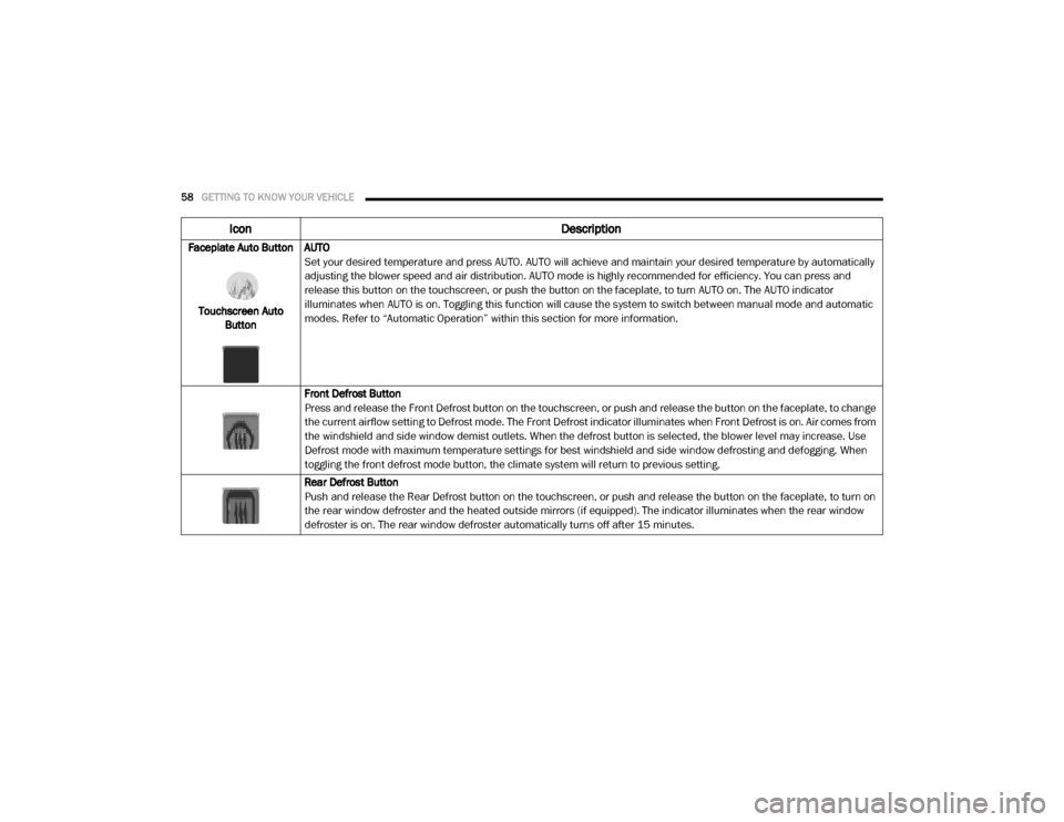
Faceplate Auto Button
Touchscreen Auto Button AUTO
Set your desired temperature and press AUTO. AUTO will achieve and maintain your desired temperature by automatically
adjusting the blower speed and air distribution. AUTO mode is highly recommended for efficiency. You can press and
release this button on the touchscreen, or push the button on the faceplate, to turn AUTO on. The AUTO indicator
illuminates when AUTO is on. Toggling this function will cause the system to switch between manual mode and automatic
modes. Refer to “Automatic Operation” within this section for more information.
Front Defrost Button
Press and release the Front Defrost button on the touchscreen, or push and release the button on the faceplate, to change
the current airflow setting to Defrost mode. The Front Defrost indicator illuminates when Front Defrost is on. Air comes from
the windshield and side window demist outlets. When the defrost button is selected, the blower level may increase. Use
Defrost mode with maximum temperature settings for best windshield and side window defrosting and defogging. When
toggling the front defrost mode button, the climate system will return to previous setting.
Rear Defrost Button
Push and release the Rear Defrost button on the touchscreen, or push and release the button on the faceplate, to turn on
the rear window defroster and the heated outside mirrors (if equipped). The indicator illuminates when the rear window
defroster is on. The rear window defroster automatically turns off after 15 minutes.
Icon
Description
2020_RAM_CHASSIS_CAB_OM_USA=GUID-6C67832B-7839-4CCF-BEFC-CDF988F949EA=1=en=.book Page 58
Page 101 of 516

GETTING TO KNOW YOUR INSTRUMENT PANEL99
Settings — If Equipped
Personal Settings allows the driver to set and
recall features when the transmission is in
PARK.
Push and release the up and down button until
Settings displays in the instrument cluster
display. Follow the prompts to display and set any of the
following Vehicle Settings.
NOTE:
Your vehicle may be equipped with the following
settings.
If equipped with a base radio (Non-Touch
-
screen) Vehicle Settings will be included in
the instrument cluster display.
If equipped with a Touchscreen radio, the
Vehicle Settings will be included in the radio
head unit.
Setting Names Setting Names Abbreviated
(Left Submenu Layer) SubMenus (Right Submenu Layer)
Language Select
Language English, Spanish, French, Italian, German, Dutch, Arabic
Units Units U.S.; Metric
ParkSense ParkSense
Front Volume — Low; Medium; High
Rear Volume — Low; Medium; High
Tilt Mirror in Reverse Tilt Mirror in R On; Off
Rain Sensing Wipers Auto Wipers On; Off
Hill Start Assist Hill Start Assist On; Off
Headlights Off Delay Lights Off Delay 0 seconds; 30 seconds; 60 seconds; 90 seconds
Illuminated Approach Lights w/ Unlock 0 seconds; 30 seconds; 60 seconds; 90 seconds
Headlights On with Wipers Lights w/ Wipers On; Off
Automatic Highbeams Auto Highbeams On; Off
Daytime Running Lights Daytime Lights On; Off
Flash Lights with Lock Lights w/ Lock On; Off
3
2020_RAM_CHASSIS_CAB_OM_USA=GUID-6C67832B-7839-4CCF-BEFC-CDF988F949EA=1=en=.book Page 99
Page 109 of 516

GETTING TO KNOW YOUR INSTRUMENT PANEL107
Battery Saver On/Battery Saver Mode
Message — Electrical Load Reduction
Actions — If Equipped
This vehicle is equipped with an Intelligent
Battery Sensor (IBS) to perform additional moni-
toring of the electrical system and status of the
vehicle battery.
In cases when the IBS detects charging system
failure, or the vehicle battery conditions are
deteriorating, electrical load reduction actions
will take place to extend the driving time and
distance of the vehicle. This is done by reducing
power to or turning off non-essential electrical
loads.
Load reduction is only active when the engine is
running. It will display a message if there is a
risk of battery depletion to the point where the
vehicle may stall due to lack of electrical supply,
or will not restart after the current drive cycle.
When load reduction is activated, the message
“Battery Saver On Some Systems May Have
Reduced Power” will appear in the instrument
cluster.
These messages indicate the vehicle battery
has a low state of charge and continues to lose
electrical charge at a rate that the charging
system cannot sustain. NOTE:
The charging system is independent from
load reduction. The charging system
performs a diagnostic on the charging
system continuously.
If the Battery Charge Warning Light is on it
may indicate a problem with the charging
system. Refer to “Battery Charge Warning
Light” in “Getting To Know Your Instrument
Panel” for further information.
The electrical loads that may be switched off (if
equipped), and vehicle functions which can be
affected by load reduction:
Heated Seats/Vented Seats/Heated Wheel
Rear Defroster And Heated Mirrors
HVAC System
115 Volt AC Power Inverter System
Audio and Telematics System Loss of the battery charge may indicate one or
more of the following conditions:
The charging system cannot deliver enough
electrical power to the vehicle system
because the electrical loads are larger than
the capability of charging system. The
charging system is still functioning properly.
Turning on all possible vehicle electrical
loads (e.g. HVAC to max settings, exterior and
interior lights, overloaded power outlets
+12 Volts, 115 Volt AC, USB ports) during
certain driving conditions (city driving,
towing, frequent stopping).
Installing options like additional lights,
upfitter electrical accessories, audio
systems, alarms and similar devices.
Unusual driving cycles (short trips separated
by long parking periods).
The vehicle was parked for an extended
period of time (weeks, months).
The battery was recently replaced and was
not charged completely.
3
2020_RAM_CHASSIS_CAB_OM_USA=GUID-6C67832B-7839-4CCF-BEFC-CDF988F949EA=1=en=.book Page 107
Page 185 of 516

183
(Continued)
STARTING AND OPERATING
STARTING THE ENGINE — GAS ENGINE
Before starting your vehicle, adjust your seat,
adjust both inside and outside mirrors, and
fasten your seat belt.
The starter should not be operated for more
than 10-second intervals. Waiting a few
seconds between such intervals will protect the
starter from overheating.
Automatic Transmission
Start the engine with the transmission in PARK
position. Apply the brake before shifting into any
driving range.NOTE:
This vehicle is equipped with a transmission
shift interlocking system. The brake pedal
must be pressed to shift out of PARK.
If equipped with an 8-speed transmission,
starting the vehicle in NEUTRAL is not
possible unless the Manual Park Release has
been activated. For the Manual Park Release
operation refer to Manual Park Release in “In
Case Of Emergency”.
Tip Start Feature
Do not
press the accelerator. Cycle the ignition
switch briefly to the START position and release
it. The starter motor will continue to run and will
automatically disengage when the engine is
running.
WARNING!
When leaving the vehicle, always make
sure the keyless ignition node is in the
"OFF" mode, remove the key fob from the
vehicle and lock the vehicle.
Never leave children alone in a vehicle, or
with access to an unlocked vehicle.
Allowing children to be in a vehicle unat -
tended is dangerous for a number of
reasons. A child or others could be seriously
or fatally injured. Children should be
warned not to touch the parking brake,
brake pedal or the gear selector.
Do not leave the key fob in or near the
vehicle, or in a location accessible to chil-
dren, and do not leave the ignition of a
vehicle equipped with Keyless Enter-N-Go
in the ACC or ON/RUN mode. A child could
operate power windows, other controls, or
move the vehicle.
Do not leave children or animals inside
parked vehicles in hot weather. Interior
heat build-up may cause serious injury or
death.
WARNING! (Continued)
5
2020_RAM_CHASSIS_CAB_OM_USA=GUID-6C67832B-7839-4CCF-BEFC-CDF988F949EA=1=en=.book Page 183
Page 189 of 516

STARTING AND OPERATING187
(Continued)
If the engine has been flooded, it may start to
run, but not have enough power to continue
running when the ignition button/key is
released. If this occurs, continue cranking with
the accelerator pedal pushed all the way to the
floor. Release the accelerator pedal and the
ignition button/key once the engine is running
smoothly.
If the engine shows no sign of starting after a 10
second period of engine cranking with the
accelerator pedal held to the floor, wait 10 to 15
seconds, then repeat the “Normal Starting”
procedure.
Cold Weather Operation (Below –22°F Or
−30°C)
To ensure reliable starting at these tempera -
tures, use of an externally powered electric
engine block heater (available from your autho -
rized dealer) is recommended.
After Starting
The idle speed is controlled automatically, and
it will decrease as the engine warms up.
STARTING THE ENGINE — DIESEL ENGINE
Before starting your vehicle, adjust your seat,
adjust both inside and outside mirrors, and
fasten your seat belts.
The starter should not be operated for more
than 25-second intervals. Waiting a few
minutes between such intervals will protect the
starter from overheating.
Automatic Transmission
Start the engine with the transmission in the
NEUTRAL or PARK position. Apply the brake
before shifting to any driving range.
CAUTION!
To prevent damage to the starter, do not
crank the engine for more than 10 seconds at
a time. Wait 10 to 15 seconds before trying
again.
WARNING!
Do not leave children or animals inside
parked vehicles in hot weather. Interior
heat build up may cause serious injury or
death.
When leaving the vehicle, always remove
the key fob and lock your vehicle.
Never leave children alone in a vehicle, or
with access to an unlocked vehicle.
Allowing children to be in a vehicle unat -
tended is dangerous for a number of
reasons. A child or others could be seriously
or fatally injured. Children should be
warned not to touch the parking brake,
brake pedal or the gear selector. Do not
leave the key fob in or near the vehicle (or
in a location accessible to children), and do
not leave the ignition of a vehicle equipped
with Keyless Enter-N-Go in the ACC or ON/
RUN mode. A child could operate power
windows, other controls, or move the
vehicle.
WARNING! (Continued)
5
2020_RAM_CHASSIS_CAB_OM_USA=GUID-6C67832B-7839-4CCF-BEFC-CDF988F949EA=1=en=.book Page 187
Page 242 of 516

240STARTING AND OPERATING
Adaptive Cruise Control Set
When the RES (+) or the SET(-) button (located
on the steering wheel) is pushed, the display will
read “ACC SET.”
When ACC is set, the set speed will show in the
instrument cluster display.
The ACC screen may display once again if any
ACC activity occurs, which may include any of
the following:
System Cancel
Driver Override
System Off
ACC Proximity Warning
ACC Unavailable Warning
The instrument cluster display will return to
the last display selected after five seconds of
no ACC display activity
Display Warnings And Maintenance
“Wipe Front Radar Sensor In Front Of
Vehicle” Warning
The “ACC/FCW Unavailable Wipe Front Radar
Sensor” warning will display and also a chime
will indicate when conditions temporarily limit
system performance. This most often occurs at times of poor visibility,
such as in snow or heavy rain. The ACC system
may also become temporarily blinded due to
obstructions, such as mud, dirt or ice. In these
cases, the instrument cluster display will display
“ACC/FCW Unavailable Wipe Front Radar
Sensor” and the system will deactivate.
The “ACC/FCW Unavailable Wipe Front Radar
Sensor” message can sometimes be displayed
while driving in highly reflective areas (i.e.
tunnels with reflective tiles, or ice and snow).
The ACC system will recover after the vehicle
has left these areas. Under rare conditions,
when the radar is not tracking any vehicles or
objects in its path this warning may temporarily
occur.
NOTE:
If the “ACC/FCW Unavailable Wipe Front Radar
Sensor” warning is active Normal (Fixed Speed)
Cruise Control is still available. For additional
information refer to “Normal (Fixed Speed)
Cruise Control Mode” in this section.
If weather conditions are not a factor, the driver
should examine the sensor. It may require
cleaning or removal of an obstruction. The
sensor is located in the camera in the center of
the windshield, on the forward side of the rear
-
view mirror. To keep the ACC System operating properly, it is
important to note the following maintenance
items:
Always keep the sensor clean. Carefully clear
the windshield.
Do not remove any screws from the sensor.
Doing so could cause an ACC system
malfunction or failure and require a sensor
realignment.
Do not attach or install any accessories near
the sensor, including transparent material or
aftermarket grilles. Doing so could cause an
ACC system failure or malfunction.
When the condition that deactivated the system
is no longer present, the system will return to
the “Adaptive Cruise Control Off” state and will
resume function by simply reactivating it.
NOTE:
If the “ACC/FCW Unavailable Wipe Front
Radar Sensor” message occurs frequently
(e.g. more than once on every trip) without
any snow, rain, mud, or other obstruction,
have the radar sensor realigned at your
authorized dealer.
2020_RAM_CHASSIS_CAB_OM_USA=GUID-6C67832B-7839-4CCF-BEFC-CDF988F949EA=1=en=.book Page 240
Page 243 of 516

STARTING AND OPERATING241
Installing a snow plow, front-end protector,
an aftermarket grille or modifying the grille is
not recommended. Doing so may block the
sensor and inhibit ACC/FCW operation.
“Clean Front Windshield” Warning
The “ACC/FCW Limited Functionality Clean
Front Windshield” warning will display and also
a chime will indicate when conditions tempo -
rarily limit system performance. This most often
occurs at times of poor visibility, such as in
snow or heavy rain and fog. The ACC system
may also become temporarily blinded due to
obstructions, such as mud, dirt, or ice on wind -
shield, driving directly into the sun and fog on
the inside of glass. In these cases, the instru -
ment cluster display will show “ACC/FCW
Limited Functionality Clean Front Windshield”
and the system will have degraded perfor -
mance.
The “ACC/FCW Limited Functionality Clean
Front Windshield” message can sometimes be
displayed while driving in adverse weather
conditions. The ACC/FCW system will recover
after the vehicle has left these areas. Under
rare conditions, when the camera is not
tracking any vehicles or objects in its path this
warning may temporarily occur. If weather conditions are not a factor, the driver
should examine the windshield and the camera
located on the back side of the inside rear view
mirror. They may require cleaning or removal of
an obstruction.
When the condition that created limited func
-
tionality is no longer present, the system will
return to full functionality.
NOTE:
If the “ACC/FCW Limited Functionality Clean
Front Windshield” message occurs frequently
(e.g. more than once on every trip) without any
snow, rain, mud, or other obstruction, have the
windshield and forward facing camera
inspected at your authorized dealer.
Service ACC/FCW Warning
If the system turns off, and the instrument
cluster displays “ACC/FCW Unavailable Service
Required” or “Cruise/FCW Unavailable Service
Required”, there may be an internal system
fault or a temporary malfunction that limits ACC
functionality. Although the vehicle is still driv -
able under normal conditions, ACC will be
temporarily unavailable. If this occurs, try acti -
vating ACC again later, following an ignition
cycle. If the problem persists, see your autho -
rized dealer.
Precautions While Driving With ACC
In certain driving situations, ACC may have
detection issues. In these cases, ACC may
brake late or unexpectedly. The driver needs to
stay alert and may need to intervene.
NOTE:
Aftermarket add-ons such as snow plows, lift
kits, and brush/grille bars can hinder module
performance. Ensure the radar/camera has
no obstructions in the field of view.
Height modifications can limit module perfor -
mance and functionality.
Do not put stickers or easy passes over the
camera/radar field of view.
Any modifications to the vehicle that may
obstruct the field of view of the radar/camera
are not recommended.
Cleaning Instructions
Dust and dirt can accumulate on the cover and
block the camera lens. Clean the camera lens
with a soft microfiber cloth, being careful not to
damage or scratch the module.
5
2020_RAM_CHASSIS_CAB_OM_USA=GUID-6C67832B-7839-4CCF-BEFC-CDF988F949EA=1=en=.book Page 241
Page 260 of 516

258STARTING AND OPERATING
When the LaneSense system senses a lane
drift situation, the left lane line turns solid
yellow. The LaneSense telltale changes
from solid green to solid yellow. At this time
torque is applied to the steering wheel in the
opposite direction of the lane boundary.
For example: If approaching the left side of
the lane the steering wheel will turn to the
right.
Lane Approached (Solid Yellow Lane Line) With Solid Yellow Telltale
When the LaneSense system senses the lane
has been approached and is in a lane depar -
ture situation, the left lane line flashes yellow
(on/off). The LaneSense telltale changes
from solid yellow to flashing yellow. At this
time torque is applied to the steering wheel in
the opposite direction of the lane boundary. For example: If approaching the left side of
the lane the steering wheel will turn to the
right.
Lane Crossed (Flashing Yellow Lane Line) With Flashing Yellow Telltale
NOTE:
The LaneSense system operates with similar
behavior for a right lane departure.
Changing LaneSense Status
The LaneSense system has settings to adjust
the intensity (Low/Medium/High) of the torque
warning and the warning zone sensitivity (Early/
Medium/Late) that you can configure through
the Uconnect system screen. Refer to
“Uconnect Settings” in “Multimedia” for further
information. NOTE:
When enabled the system operates above
37 mph (60 km/h) and below 112 mph
(180 km/h).
Use of the turn signal suppresses the warn -
ings.
The system will not apply torque to the
steering wheel whenever a safety system
engages (Anti-Lock Brakes, Traction Control
System, Electronic Stability Control, Forward
Collision Warning, etc.).
PARKVIEW REAR BACK UP CAMERA
Your vehicle may be equipped with the
ParkView Rear Back Up Camera that allows you
to see a image of the rear surroundings of your
vehicle whenever the gear selector is put into
REVERSE or whenever it is initiated through the
"Backup Camera" button in the "Controls"
menu. Whenever the gear selector is put into
REVERSE, the image will be displayed in the
rearview mirror display (if equipped) or
Uconnect screen (if equipped). If the image is
displayed in the Uconnect screen, a caution
note to “check entire surroundings” will display
across the top of the screen. After five seconds
this note will disappear.
2020_RAM_CHASSIS_CAB_OM_USA=GUID-6C67832B-7839-4CCF-BEFC-CDF988F949EA=1=en=.book Page 258
Page 263 of 516

STARTING AND OPERATING261
AUX Camera — If Equipped
Your vehicle may be equipped with one or two
AUX Cameras, which display a rearview image
from the trailer on the touchscreen.
Activation
The AUX Camera is activated by first pressing
the Backup Camera, Cargo Camera (if
equipped), or Surround View Camera (if
equipped) button on the touchscreen, followed
by the AUX button located in the upper left
corner of the rearview display. The AUX camera
can also be activated when the vehicle is in
REVERSE by pressing the AUX button.
If equipped with two AUX Cameras, you can
switch between each camera by then pressing
the AUX1 or AUX2 buttons on the Trailer Camera
display.
AUX1 Camera Button
AUX2 Camera Button Deactivation
The AUX Camera is deactivated by pressing the
“X” in the upper right corner of the touchscreen.
This will return the display back to the previ
-
ously displayed screen.
NOTE:
If the AUX button is pressed and no AUX
Camera is connected, the touchscreen will
display a blue screen along with the message
“Camera System Unavailable.” The screen
can be exited out by pressing the “X” in the
upper right hand corner. This will return the
display back to the previously displayed
screen.
Zoom View is not available with the AUX
Camera feature.
The display will always default to the Trailer
Camera display (AUX 1).
SURROUND VIEW CAMERA SYSTEM — IF
EQUIPPED
Your vehicle may be equipped with the
Surround View Camera System that allows you
to see an on-screen image of the surroundings
and top view of your vehicle whenever the gear
selector is put into REVERSE or manually acti -
vated via the Uconnect system. The top view of
the vehicle will show which doors are open. The
image will be displayed on the touchscreen
display along with a caution note “Check Entire
Surroundings” across the top of the screen.
After five seconds, this note will disappear. The
Surround View Camera System is comprised of
three sequential cameras located in the front
grille and side mirrors, in addition to a fourth
Rear Back Up Camera.
5
2020_RAM_CHASSIS_CAB_OM_USA=GUID-6C67832B-7839-4CCF-BEFC-CDF988F949EA=1=en=.book Page 261
Page 264 of 516

262STARTING AND OPERATING
NOTE:
For the 3500, 4500, and 5500 Chassis Cab
vehicles, the Rear Backup Camera is shipped
loose and not installed. Please refer to the
Ram Body Builder’s Guide for more informa -
tion.
The Surround View Camera System has
programmable settings that may be selected
through the Uconnect System. Refer to
“Uconnect Settings” in “Multimedia” for
further information.
When the vehicle is shifted into REVERSE, the
rear camera view and top view is the default
view of the system (Automatic Activation).
When the vehicle is shifted out of REVERSE
(with camera delay turned on), the camera
image will continue to be displayed for up to 10
seconds after shifting out of REVERSE unless
the vehicle speed exceeds 8 mph (13 km/h),
the vehicle is shifted into PARK or the ignition is
placed in the OFF position. There is a touch -
screen button “X” to disable the display of the
camera image.
When the vehicle is shifted out of REVERSE
(with camera delay turned off), the surround
view camera mode is exited and the last known
screen appears again. Modes Of Operation
Standard Backup Camera view can be manually
activated by selecting “Backup Camera”
through the Controls menu within the Uconnect
screen.
Refer to “Parkview Rear Back Up Camera” in
this chapter for more information on activation
conditions.
Top View
The Top view will show in the Uconnect System
with Rear view and Front view in a split view
display. There are integrated ParkSense arcs in
the image at the front and rear of the vehicle.
The arcs will change color from yellow to red
corresponding the distance zones to the
oncoming object.
The fifth button of the ParkSense Camera View
screen will be changed based on the features
present in the vehicle. If not equipped with a
Cargo Camera or Trailer Reverse Guidance, the
Backup Camera soft button will be displayed. If
equipped with a Cargo Camera but no Trailer
Reverse Guidance, the Cargo Camera soft
button will be displayed, and if equipped with
both a Cargo Camera and Trailer Reverse Guid
-
ance, the Cargo/Trailer Reverse Guidance soft
button will be displayed.
ParkSense Camera View
NOTE:
Front tires will be in image when the tires are
turned.
Due to wide angle cameras in mirror, the
image will appear distorted.
Top view will show which doors are open.
Open front doors will remove outside image.
Rear View This is the Default view of the system
in REVERSE and is always paired with
the Top view of the vehicle with
optional active guide lines for the
projected path when enabled.
2020_RAM_CHASSIS_CAB_OM_USA=GUID-6C67832B-7839-4CCF-BEFC-CDF988F949EA=1=en=.book Page 262