radio Ram 3500 Chassis Cab 2020 User Guide
[x] Cancel search | Manufacturer: RAM, Model Year: 2020, Model line: 3500 Chassis Cab, Model: Ram 3500 Chassis Cab 2020Pages: 516, PDF Size: 29.24 MB
Page 34 of 516
32GETTING TO KNOW YOUR VEHICLE
Power Lumbar — If Equipped
Vehicles equipped with power driver or
passenger seats may be also be equipped with
power lumbar. The power lumbar switch is
located on the outboard side of the power seat.
Push the switch forward to increase the lumbar
support. Push the switch rearward to decrease
the lumbar support.
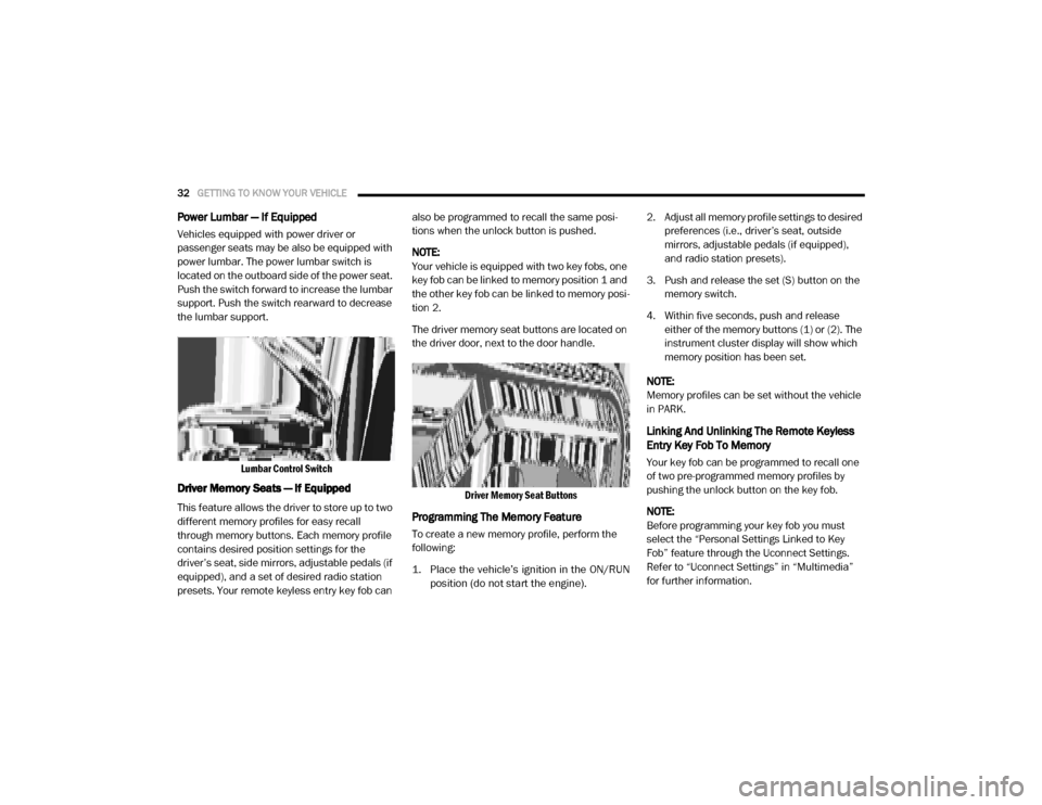
Lumbar Control Switch
Driver Memory Seats — If Equipped
This feature allows the driver to store up to two
different memory profiles for easy recall
through memory buttons. Each memory profile
contains desired position settings for the
driver’s seat, side mirrors, adjustable pedals (if
equipped), and a set of desired radio station
presets. Your remote keyless entry key fob can also be programmed to recall the same posi
-
tions when the unlock button is pushed.
NOTE:
Your vehicle is equipped with two key fobs, one
key fob can be linked to memory position 1 and
the other key fob can be linked to memory posi -
tion 2.
The driver memory seat buttons are located on
the driver door, next to the door handle.
Driver Memory Seat Buttons
Programming The Memory Feature
To create a new memory profile, perform the
following:
1. Place the vehicle’s ignition in the ON/RUNposition (do not start the engine).
2. Adjust all memory profile settings to desired
preferences (i.e., driver’s seat, outside
mirrors, adjustable pedals (if equipped),
and radio station presets).
3. Push and release the set (S) button on the memory switch.
4. Within five seconds, push and release either of the memory buttons (1) or (2). The
instrument cluster display will show which
memory position has been set.
NOTE:
Memory profiles can be set without the vehicle
in PARK.
Linking And Unlinking The Remote Keyless
Entry Key Fob To Memory
Your key fob can be programmed to recall one
of two pre-programmed memory profiles by
pushing the unlock button on the key fob.
NOTE:
Before programming your key fob you must
select the “Personal Settings Linked to Key
Fob” feature through the Uconnect Settings.
Refer to “Uconnect Settings” in “Multimedia”
for further information.
2020_RAM_CHASSIS_CAB_OM_USA=GUID-6C67832B-7839-4CCF-BEFC-CDF988F949EA=1=en=.book Page 32
Page 53 of 516
GETTING TO KNOW YOUR VEHICLE51
Rain Sensing Wipers — If Equipped
This feature senses moisture on the windshield
and automatically activates the wipers for the
driver. The feature is especially useful for road
splash or overspray from the windshield
washers of the vehicle ahead. Rotate the end of
the multifunction lever to one of five settings to
activate this feature.
NOTE:
This feature can be programmed through the
Uconnect system. Refer to “Uconnect Settings”
in “Multimedia” for further information.
The sensitivity of the system can be adjusted
with the multifunction lever. Wiper delay posi -
tion 1 is the least sensitive, and wiper delay
position 5 is the most sensitive. Position 3
should be used for normal rain conditions. Posi -
tions 1 and 2 can be used if the driver desires
less wiper sensitivity. Positions 4 and 5 can be
used if the driver desires more sensitivity. Place
the wiper switch in the O (off) position when not
using the system. NOTE:The Rain Sensing feature will not operate
when the wiper switch is in the low or
high-speed position.
The Rain Sensing feature may not function
properly when ice, or dried salt water is
present on the windshield.
Use of Rain-X or products containing wax or
silicone may reduce Rain Sensing perfor
-
mance.
The Rain Sensing system has protection
features for the wiper blades and arms, and will
not operate under the following conditions:
Low Ambient Temperature — When the igni-
tion is first placed in the ON position, the Rain
Sensing system will not operate until the
wiper switch is moved, vehicle speed is
greater than 0 mph (0 km/h), or the outside
temperature is greater than 32°F (0°C).
Transmission In NEUTRAL Position — When
the ignition is ON, and the transmission is in
the NEUTRAL position, the Rain Sensing
system will not operate until the wiper switch
is moved, vehicle speed is greater than
5 mph (8 km/h), or the gear selector is
moved out of the NEUTRAL position.
Remote Start Mode Inhibit — On vehicles
equipped with Remote Starting system, Rain
Sensing wipers are not operational when the
vehicle is in the remote start mode. Once the
operator is in the vehicle and has placed the
ignition switch in the RUN position, Rain
Sensing wiper operation can resume, if it has
been selected, and no other inhibit condi -
tions (mentioned previously) exist.
CLIMATE CONTROLS
The Climate Control system allows you to regu -
late the temperature, air flow, and direction of
air circulating throughout the vehicle. The
controls are located on the touchscreen (if
equipped), on the sides of the touchscreen, or
on the instrument panel below the radio.
2
2020_RAM_CHASSIS_CAB_OM_USA=GUID-6C67832B-7839-4CCF-BEFC-CDF988F949EA=1=en=.book Page 51
Page 62 of 516
60GETTING TO KNOW YOUR VEHICLE
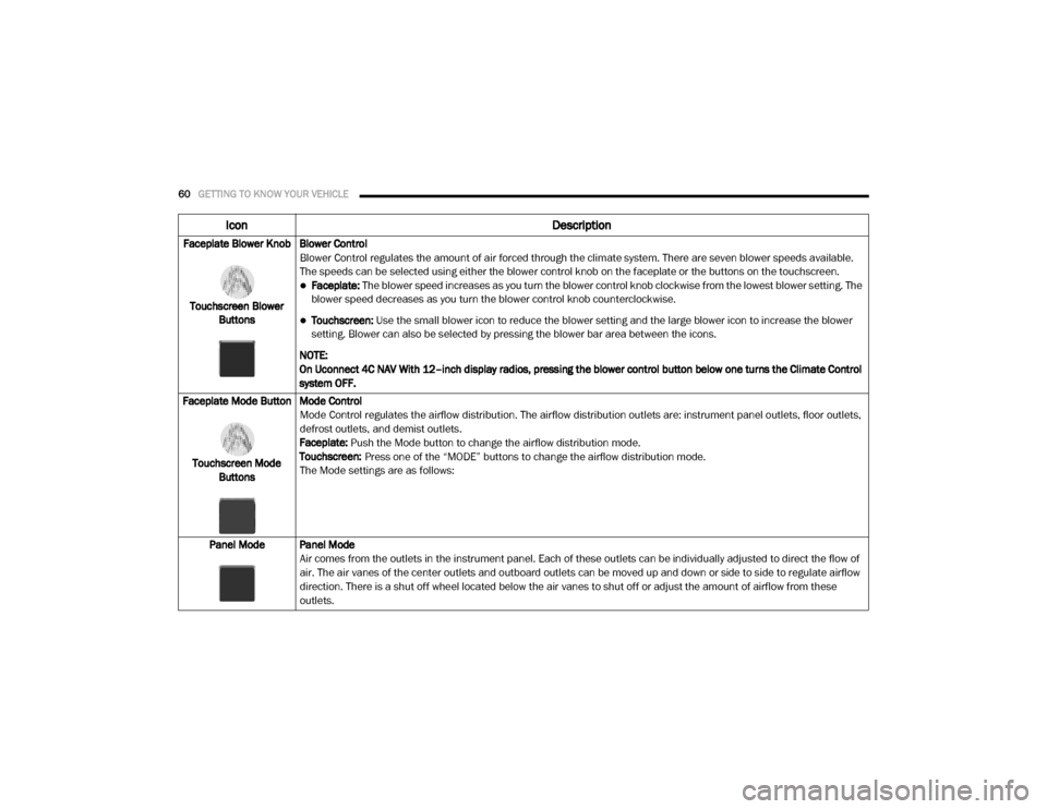
Faceplate Blower Knob
Touchscreen Blower Buttons Blower Control
Blower Control regulates the amount of air forced through the climate system. There are seven blower speeds available.
The speeds can be selected using either the blower control knob on the faceplate or the buttons on the touchscreen.
Faceplate: The blower speed increases as you turn the blower control knob clockwise from the lowest blower setting. The
blower speed decreases as you turn the blower control knob counterclockwise.
Touchscreen:
Use the small blower icon to reduce the blower setting and the large blower icon to increase the blower
setting. Blower can also be selected by pressing the blower bar area between the icons.
NOTE:
On Uconnect 4C NAV With 12–inch display radios, pressing the blower control button below one turns the Climate Control
system OFF.
Faceplate Mode Button
Touchscreen Mode Buttons Mode Control
Mode Control regulates the airflow distribution. The airflow distribution outlets are: instrument panel outlets, floor outlets,
defrost outlets, and demist outlets.
Faceplate: Push the Mode button to change the airflow distribution mode.
Touchscreen:
Press one of the “MODE” buttons to change the airflow distribution mode.
The Mode settings are as follows:
Panel Mode Panel Mode Air comes from the outlets in the instrument panel. Each of these outlets can be individually adjusted to direct the flow of
air. The air vanes of the center outlets and outboard outlets can be moved up and down or side to side to regulate airflow
direction. There is a shut off wheel located below the air vanes to shut off or adjust the amount of airflow from these
outlets.
Icon Description
2020_RAM_CHASSIS_CAB_OM_USA=GUID-6C67832B-7839-4CCF-BEFC-CDF988F949EA=1=en=.book Page 60
Page 70 of 516

68GETTING TO KNOW YOUR VEHICLE
NOTE:
Only use this transceiver with a garage door
opener that has a “stop and reverse” feature as
required by federal safety standards. This
includes most garage door opener models
manufactured after 1982. Do not use a garage
door opener without these safety features. Call
toll-free 1-800-355-3515 or, on the Internet at
HomeLink.com for safety information or assis -
tance.
Before You Begin Programming HomeLink®
Be sure that your vehicle is parked outside of
the garage before you begin programming.
For more efficient programming and accurate
transmission of the radio-frequency signal it is
recommended that a new battery be placed in
the hand-held transmitter of the device that is
being programmed to the HomeLink® system.
To erase the channels, place the ignition in the
ON/RUN position, and push and hold the two
outside HomeLink® buttons (I and III) for up to
20 seconds or until the orange indicator
flashes. NOTE:
Erasing all channels should only be
performed when programming HomeLink®
for the first time. Do not erase channels when
programming additional buttons.
If you have any problems, or require assis
-
tance, please call toll-free 1-800-355-3515
or, on the Internet at HomeLink.com for infor-
mation or assistance.
Programming A Rolling Code
For programming garage door openers that
were manufactured after 1995. These garage
door openers can be identified by the “LEARN”
or “TRAIN” button located where the hanging
antenna is attached to the garage door opener.
NOTE:
It is NOT the button that is normally used to
open and close the door. The name and color of
the button may vary by manufacturer.
Training The Garage Door Opener
1. Place the ignition in the ON/RUN position.
2. Place the hand-held transmitter 1 to 3 inches (3 to 8 cm) away from the Home-
Link® button you wish to program while
keeping the HomeLink® indicator light in
view.
3. Push and hold the HomeLink® button you want to program while you push and hold
the hand-held transmitter button.
1 — Door Opener
2 — Training Button
2020_RAM_CHASSIS_CAB_OM_USA=GUID-6C67832B-7839-4CCF-BEFC-CDF988F949EA=1=en=.book Page 68
Page 72 of 516

70GETTING TO KNOW YOUR VEHICLE
Reprogramming A Single HomeLink® Button
(Non-Rolling Code)
To reprogram a channel that has been previ -
ously trained, follow these steps:
1. Place the ignition in the ON/RUN position.
2. Press and hold the desired HomeLink® button until the indicator light begins to
flash after 20 seconds. Do not release the
button.
3. Without releasing the button, proceed with “Programming A Non-Rolling Code” step 2
and follow all remaining steps.
Canadian/Gate Operator Programming
For programming transmitters in Canada/
United States that require the transmitter
signals to “time-out” after several seconds of
transmission.
Canadian radio frequency laws require trans -
mitter signals to time-out (or quit) after several
seconds of transmission – which may not be
long enough for HomeLink® to pick up the
signal during programming. Similar to this
Canadian law, some U.S. gate operators are
designed to time-out in the same manner. It may be helpful to unplug the device during the
cycling process to prevent possible overheating
of the garage door or gate motor.
1. Place the ignition in the ON/RUN position.
2. Place the hand-held transmitter 1 to
3 inches (3 to 8 cm) away from the Home-
Link® button you wish to program while
keeping the HomeLink® indicator light in
view.
3. Continue to press and hold the HomeLink® button, while you press and release
(“cycle”) your hand-held transmitter every
two seconds until HomeLink® has success-
fully accepted the frequency signal. The
indicator light will flash slowly and then
rapidly when fully trained.
4. Watch for the HomeLink® indicator to change flash rates. When it changes, it is
programmed. It may take up to 30 seconds
or longer in rare cases. The garage door
may open and close while you are program -
ming. 5. Press and hold the programmed Home
-
Link® button and observe the indicator
light.
NOTE:
If the indicator light stays on constantly,
programming is complete and the garage
door/device should activate when the
HomeLink® button is pressed.
To program the two remaining HomeLink®
buttons, repeat each step for each
remaining button. DO NOT erase the chan -
nels.
If you unplugged the garage door opener/
device for programming, plug it back in at this
time.
Reprogramming A Single HomeLink® Button
(Canadian/Gate Operator)
To reprogram a channel that has been previ -
ously trained, follow these steps:
1. Place the ignition in the ON/RUN position.
2020_RAM_CHASSIS_CAB_OM_USA=GUID-6C67832B-7839-4CCF-BEFC-CDF988F949EA=1=en=.book Page 70
Page 74 of 516

72GETTING TO KNOW YOUR VEHICLE
General Information
The following regulatory statement applies to all
Radio Frequency (RF) devices equipped in this
vehicle:
This device complies with Part 15 of the FCC
Rules and with Innovation, Science and
Economic Development Canada license-exempt
RSS standard(s). Operation is subject to the
following two conditions:
1. This device may not cause harmful interfer -
ence, and
2. This device must accept any interference received, including interference that may
cause undesired operation.
Le présent appareil est conforme aux CNR
d`Innovation, Science and Economic Develop -
ment applicables aux appareils radio exempts
de licence. L'exploitation est autorisée aux deux
conditions suivantes:
1. l'appareil ne doit pas produire de brouil -
lage, et
2. l'utilisateur de l'appareil doit accepter tout brouillage radioélectrique subi, même si le
brouillage est susceptible d'en comprom -
ettre le fonctionnement. La operación de este equipo está sujeta a las
siguientes dos condiciones:
1. es posible que este equipo o dispositivo no
cause interferencia perjudicial y
2. este equipo o dispositivo debe aceptar cual -
quier interferencia, incluyendo la que
pueda causar su operación no deseada.
NOTE:
Changes or modifications not expressly
approved by the party responsible for compli -
ance could void the user’s authority to operate
the equipment.
INTERNAL EQUIPMENT
Storage
Glove Compartment
The glove compartment is located on the
passenger side of the instrument panel and
features both an upper and lower storage area.
NOTE:
Not all vehicles are equipped with a door over
the upper storage area.
Glove Compartment
If equipped with a covered upper glove compart -
ment, push the release button to open.
To open the lower glove compartment, pull the
release handle.
1 — Upper Glove Compartment Release Button (If
Equipped)
2 — Upper Glove Compartment
3 — Lower Glove Compartment
2020_RAM_CHASSIS_CAB_OM_USA=GUID-6C67832B-7839-4CCF-BEFC-CDF988F949EA=1=en=.book Page 72
Page 101 of 516
GETTING TO KNOW YOUR INSTRUMENT PANEL99
Settings — If Equipped
Personal Settings allows the driver to set and
recall features when the transmission is in
PARK.
Push and release the up and down button until
Settings displays in the instrument cluster
display. Follow the prompts to display and set any of the
following Vehicle Settings.
NOTE:
Your vehicle may be equipped with the following
settings.
If equipped with a base radio (Non-Touch
-
screen) Vehicle Settings will be included in
the instrument cluster display.
If equipped with a Touchscreen radio, the
Vehicle Settings will be included in the radio
head unit.
Setting Names Setting Names Abbreviated
(Left Submenu Layer) SubMenus (Right Submenu Layer)
Language Select
Language English, Spanish, French, Italian, German, Dutch, Arabic
Units Units U.S.; Metric
ParkSense ParkSense
Front Volume — Low; Medium; High
Rear Volume — Low; Medium; High
Tilt Mirror in Reverse Tilt Mirror in R On; Off
Rain Sensing Wipers Auto Wipers On; Off
Hill Start Assist Hill Start Assist On; Off
Headlights Off Delay Lights Off Delay 0 seconds; 30 seconds; 60 seconds; 90 seconds
Illuminated Approach Lights w/ Unlock 0 seconds; 30 seconds; 60 seconds; 90 seconds
Headlights On with Wipers Lights w/ Wipers On; Off
Automatic Highbeams Auto Highbeams On; Off
Daytime Running Lights Daytime Lights On; Off
Flash Lights with Lock Lights w/ Lock On; Off
3
2020_RAM_CHASSIS_CAB_OM_USA=GUID-6C67832B-7839-4CCF-BEFC-CDF988F949EA=1=en=.book Page 99
Page 104 of 516
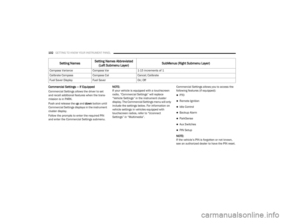
102GETTING TO KNOW YOUR INSTRUMENT PANEL
Commercial Settings — If Equipped
Commercial Settings allows the driver to set
and recall additional features when the trans-
mission is in PARK.
Push and release the up and down button until
Commercial Settings displays in the instrument
cluster display.
Follow the prompts to enter the required PIN
and enter the Commercial Settings submenu. NOTE:
If your vehicle is equipped with a touchscreen
radio, “Commercial Settings” will replace
“Vehicle Settings” in the instrument cluster
display. The Commercial Settings menu will only
include the settings below. For information on
vehicle settings in vehicles equipped with
touchscreen radios, refer to “Uconnect
Settings” in “Multimedia”.
Commercial Settings allows you to access the
following features (if equipped):PTO
Remote Ignition
Idle Control
Backup Alarm
ParkSense
Aux Switches
PIN Setup
NOTE:
If the vehicle’s PIN is forgotten or not known,
see an authorized dealer to have the PIN reset.
Compass Variance
Compass Var 1-15 increments of 1
Calibrate Compass Compass Cal Cancel; Calibrate
Fuel Saver Display Fuel Saver On; Off
Setting NamesSetting Names Abbreviated
(Left Submenu Layer) SubMenus (Right Submenu Layer)
2020_RAM_CHASSIS_CAB_OM_USA=GUID-6C67832B-7839-4CCF-BEFC-CDF988F949EA=1=en=.book Page 102
Page 110 of 516

108GETTING TO KNOW YOUR INSTRUMENT PANEL
The battery was discharged by an electrical
load left on when the vehicle was parked.
The battery was used for an extended period
with the engine not running to supply radio,
lights, chargers, +12 Volt portable appli-
ances like vacuum cleaners, game consoles
and similar devices.
What to do when an electrical load reduction
action message is present (“Battery Saver On”
or “Battery Saver Mode”)
During a trip:
Reduce power to unnecessary loads if
possible:
Turn off redundant lights (interior or exte -
rior).
Check what may be plugged in to power outlets +12 Volts, 115 Volt AC, USB ports.
Check HVAC settings (blower, tempera -
ture).
Check the audio settings (volume). After a trip:
Check if any aftermarket equipment was
installed (additional lights, upfitter electrical
accessories, audio systems, alarms) and
review specifications if any (load and Ignition
Off Draw currents).
Evaluate the latest driving cycles (distance,
driving time and parking time).
The vehicle should have service performed if
the message is still present during consecu
-
tive trips and the evaluation of the vehicle
and driving pattern did not help to identify the
cause.
WARNING LIGHTS AND MESSAGES
The warning/indicator lights will illuminate in
the instrument panel together with a dedicated
message and/or acoustic signal when appli -
cable. These indications are indicative and
precautionary and as such must not be consid -
ered as exhaustive. Always refer to the informa-
tion in this chapter in the event of a failure
indication. All active telltales will display first if
applicable. The system check menu may
appear different based upon equipment
options and current vehicle status. Some tell -
tales are optional and may not appear.
Red Warning Lights
Seat Belt Reminder Warning Light
This warning light indicates when the
driver or passenger seat belt is
unbuckled. When the ignition is first
placed in the ON/RUN or ACC/ON/
RUN position and if the driver’s seat belt is
unbuckled, a chime will sound and the light will
turn on. When driving, if the driver or front
passenger seat belt remains unbuckled, the
Seat Belt Reminder Light will flash or remain on
continuously and a chime will sound.
Refer to “Occupant Restraint Systems” in
“Safety” for further information.
Air Bag Warning Light
This warning light will illuminate to
indicate a fault with the air bag, and
will turn on for four to eight seconds
as a bulb check when the ignition is
placed in the ON/RUN or ACC/ON/RUN posi -
tion. This light will illuminate with a single chime
when a fault with the air bag has been detected,
it will stay on until the fault is cleared. If the light
is either not on during startup, stays on, or turns
on while driving, have the system inspected at
an authorized dealer as soon as possible.
2020_RAM_CHASSIS_CAB_OM_USA=GUID-6C67832B-7839-4CCF-BEFC-CDF988F949EA=1=en=.book Page 108
Page 122 of 516

120(Continued)
SAFETY
SAFETY FEATURES
Anti-Lock Brake System (ABS)
The Anti-Lock Brake System (ABS) provides
increased vehicle stability and brake perfor-
mance under most braking conditions. The
system automatically prevents wheel lock, and
enhances vehicle control during braking.
The ABS performs a self-check cycle to ensure
that the ABS is working properly each time the
vehicle is started and driven. During this
self-check, you may hear a slight clicking sound
as well as some related motor noises.
ABS is activated during braking when the
system detects one or more wheels begin to
lock. Road conditions such as ice, snow, gravel,
bumps, railroad tracks, loose debris, or panic
stops may increase the likelihood of ABS activa-
tion(s). You also may experience the following when
ABS activates:
The ABS motor noise (it may continue to run
for a short time after the stop)
The clicking sound of solenoid valves
Brake pedal pulsations
A slight drop of the brake pedal at the end of
the stop
These are all normal characteristics of ABS.
WARNING!
The ABS contains sophisticated electronic
equipment that may be susceptible to inter -
ference caused by improperly installed or
high output radio transmitting equipment.
This interference can cause possible loss of
anti-lock braking capability. Installation of
such equipment should be performed by
qualified professionals.
Pumping of the Anti-Lock Brakes will
diminish their effectiveness and may lead
to a collision. Pumping makes the stopping
distance longer. Just press firmly on your
brake pedal when you need to slow down or
stop.
The ABS cannot prevent the natural laws of
physics from acting on the vehicle, nor can
it increase braking or steering efficiency
beyond that afforded by the condition of the
vehicle brakes and tires or the traction
afforded.
The ABS cannot prevent collisions,
including those resulting from excessive
speed in turns, following another vehicle
too closely, or hydroplaning.
The capabilities of an ABS equipped vehicle
must never be exploited in a reckless or
dangerous manner that could jeopardize
the user’s safety or the safety of others.
WARNING! (Continued)
2020_RAM_CHASSIS_CAB_OM_USA=GUID-6C67832B-7839-4CCF-BEFC-CDF988F949EA=1=en=.book Page 120