battery Ram 4500 Chassis Cab 2018 Owner's Manual
[x] Cancel search | Manufacturer: RAM, Model Year: 2018, Model line: 4500 Chassis Cab, Model: Ram 4500 Chassis Cab 2018Pages: 298, PDF Size: 5.88 MB
Page 64 of 298

WARNING!
Have the vehicle checked immediately.
Vehicles equipped with the Anti-Lock Brake
System (ABS) are also equipped with Elec-
tronic Brake Force Distribution (EBD). In the
event of an EBD failure, the Brake Warning
Light will turn on along with the ABS Light.
Immediate repair to the ABS system is re-
quired.
Operation of the Brake Warning Light can be
checked by turning the ignition switch from
the OFF position to the ON/RUN position.
The light should illuminate for approximately
two seconds. The light should then turn off
unless the parking brake is applied or a brake
fault is detected. If the light does not illumi-
nate, have the light inspected by your autho-
rized dealer.
The light also will turn on when the parking
brake is applied with the ignition switch in
the ON/RUN position. NOTE:
This light shows only that the parking brake is
applied. It does not show the degree of brake
application.
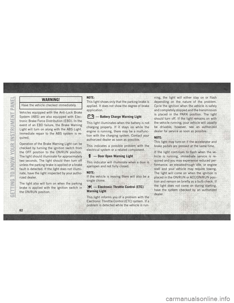
— Battery Charge Warning Light
This light illuminates when the battery is not
charging properly. If it stays on while the
engine is running, there may be a malfunc-
tion with the charging system. Contact your
authorized dealer as soon as possible.
This indicates a possible problem with the
electrical system or a related component.
— Door Open Warning Light
This indicator will illuminate when a door is
ajar/open and not fully closed.
NOTE:
If the vehicle is moving there will also be a
single chime.
— Electronic Throttle Control (ETC)
Warning Light
This light informs you of a problem with the
Electronic Throttle Control (ETC) system. If a
problem is detected while the vehicle is run- ning, the light will either stay on or flash
depending on the nature of the problem.
Cycle the ignition when the vehicle is safely
and completely stopped and the transmission
is placed in the PARK position. The light
should turn off. If the light remains on with
the vehicle running, your vehicle will usually
be drivable; however, see an authorized
dealer for service as soon as possible.
NOTE:
This light may turn on if the accelerator and
brake pedals are pressed at the same time.
If the light continues to flash when the ve-
hicle is running, immediate service is re-
quired and you may experience reduced per-
formance, an elevated/rough idle, or engine
stall and your vehicle may require towing.
The light will come on when the ignition is
placed in the ON/RUN or ACC/ON/RUN posi-
tion and remain on briefly as a bulb check. If
the light does not come on during starting,
have the system checked by an authorized
dealer.GETTING TO KNOW YOUR INSTRUMENT PANEL
62
Page 90 of 298

ON/RUN position. If the ignition switch is in
the OFF position or in the ACC position, the
air bag system is not on and the air bags will
not inflate.
The ORC contains a backup power supply
system that may deploy the air bag system
even if the battery loses power or it becomes
disconnected prior to deployment.
The ORC turns on the Air Bag Warning Light
in the instrument panel for approximately
four to eight seconds for a self-check when
the ignition switch is first in the ON/RUN
position. After the self-check, the Air Bag
Warning Light will turn off. If the ORC detects
a malfunction in any part of the system, it
turns on the Air Bag Warning Light, either
momentarily or continuously. A single chime
will sound to alert you if the light comes on
again after initial startup.
The ORC also includes diagnostics that will
illuminate the instrument panel Air Bag
Warning Light if a malfunction is detected
that could affect the air bag system. The
diagnostics also record the nature of the
malfunction. While the air bag system isdesigned to be maintenance free, if any of
the following occurs, have an authorized
dealer service the air bag system immedi-
ately.
• The Air Bag Warning Light does not come
on during the four to eight seconds when
the ignition switch is first in the ON/RUN
position.
• The Air Bag Warning Light remains on after the four to eight-second interval.
• The Air Bag Warning Light comes on inter- mittently or remains on while driving.
NOTE:
If the speedometer, tachometer, or any en-
gine related gauges are not working, the Oc-
cupant Restraint Controller (ORC) may also
be disabled. In this condition the air bags
may not be ready to inflate for your protec-
tion. Have an authorized dealer service the
air bag system immediately.WARNING!
Ignoring the Air Bag Warning Light in your
instrument panel could mean you won’t
have the air bag system to protect you in a
collision. If the light does not come on as a
bulb check when the ignition is first
turned on, stays on after you start the
vehicle, or if it comes on as you drive, have
an authorized dealer service the air bag
system immediately.
Front Air Bags
This vehicle has front air bags and lap/
shoulder belts for both the driver and front
passenger. The front air bags are a supple-
ment to the seat belt restraint systems. The
driver front air bag is mounted in the center
of the steering wheel. The passenger front air
bag is mounted in the instrument panel,
above the glove compartment. The words
“SRS AIRBAG” or “AIRBAG” are embossed
on the air bag covers.
SAFETY
88
Page 96 of 298

• Front and Side Impact Sensors — IfEquipped
• Seat Belt Pretensioners — If Equipped
If A Deployment Occurs
The front air bags are designed to deflate
immediately after deployment.
NOTE:
Front and/or side air bags will not deploy in
all collisions. This does not mean something
is wrong with the air bag system.
If you do have a collision which deploys the
air bags, any or all of the following may occur:
• The air bag material may sometimes cause abrasions and/or skin reddening to the oc-
cupants as the air bags deploy and unfold.
The abrasions are similar to friction rope
burns or those you might get sliding along a
carpet or gymnasium floor. They are not
caused by contact with chemicals. They are
not permanent and normally heal quickly.
However, if you haven’t healed significantly
within a few days, or if you have any blis-
tering, see your doctor immediately.
• As the air bags deflate, you may see some smoke-like particles. The particles are a normal by-product of the process that gen-
erates the non-toxic gas used for air bag
inflation. These airborne particles may irri-
tate the skin, eyes, nose, or throat. If you
have skin or eye irritation, rinse the area
with cool water. For nose or throat irritation,
move to fresh air. If the irritation continues,
see your doctor. If these particles settle on
your clothing, follow the garment manufac-
turer’s instructions for cleaning.
Do not drive your vehicle after the air bags
have deployed. If you are involved in another
collision, the air bags will not be in place to
protect you.
WARNING!
Deployed air bags and seat belt preten-
sioners cannot protect you in another col-
lision. Have the air bags, seat belt preten-
sioners, and the seat belt retractor
assemblies replaced by an authorized
dealer immediately. Also, have the Occu-
pant Restraint Controller System serviced
as well. NOTE:
• Air bag covers may not be obvious in the
interior trim, but they will open during air
bag deployment.
• After any collision, the vehicle should be taken to an authorized dealer immediately.
Enhanced Accident Response System
In the event of an impact, if the communica-
tion network remains intact, and the power
remains intact, depending on the nature of
the event, the ORC will determine whether to
have the Enhanced Accident Response Sys-
tem perform the following functions:
• Cut off fuel to the engine.
• Flash hazard lights as long as the batteryhas power or until the hazard light button is
pressed. The hazard lights can be deacti-
vated by pressing the hazard light button.
• Turn on the interior lights, which remain on as long as the battery has power.
• Unlock the power door locks.
SAFETY
94
Page 156 of 298

HAZARD WARNING FLASHERS
The Hazard Warning flasher switch is located
on the upper switch bank just below the
radio.
Push the switch to turn on the Hazard Warn-
ing flasher. When the switch is activated, all
directional turn signals will flash on and off to
warn oncoming traffic of an emergency. Push
the switch a second time to turn off the
Hazard Warning flashers.
This is an emergency warning system and it
should not be used when the vehicle is in
motion. Use it when your vehicle is disabled
and it is creating a safety hazard for other
motorists.
When you must leave the vehicle to seek
assistance, the Hazard Warning flashers will
continue to operate even though the ignition
is placed in the OFF position.
NOTE:
With extended use the Hazard Warning flash-
ers may wear down your battery.
BULB REPLACEMENT
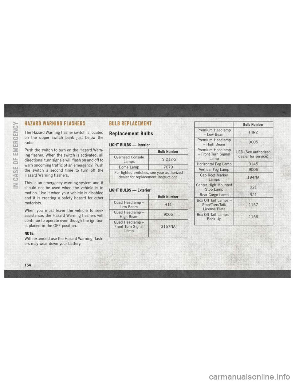
Replacement Bulbs
LIGHT BULBS — Interior
Bulb Number
Overhead Console Lamps TS 212-2
Dome Lamp 7679
For lighted switches, see your authorized dealer for replacement instructions.
LIGHT BULBS — Exterior
Bulb Number
Quad Headlamp – Low Beam H11
Quad Headlamp – High Beam 9005
Quad Headlamp – Front Turn Signal Lamp 3157NA
Bulb Number
Premium Headlamp – Low Beam HIR2
Premium Headlamp – High Beam 9005
Premium Headlamp – Front Turn Signal Lamp LED (See authorized
dealer for service)
Horizontal Fog Lamp 9145 Vertical Fog Lamp 9006
Cab Roof Marker Lamps 194NA
Center High Mounted Stop Lamp 921
Rear Cargo Lamp 921
Box Off Tail Lamps – Stop/Turn/Tail/License Plate 1157
Box Off Tail Lamps – Back Up 1156
IN CASE OF EMERGENCY
154
Page 157 of 298

FUSES
WARNING!
• When replacing a blown fuse, always usean appropriate replacement fuse with
the same amp rating as the original fuse.
Never replace a fuse with another fuse of
higher amp rating. Never replace a
blown fuse with metal wires or any other
material. Do not place a fuse inside a
circuit breaker cavity or vice versa. Fail-
ure to use proper fuses may result in
serious personal injury, fire and/or prop-
erty damage.
WARNING!
• Before replacing a fuse, make sure thatthe ignition is off and that all the other
services are switched off and/or disen-
gaged.
• If the replaced fuse blows again, contact
an authorized dealer.
• If a general protection fuse for safety
systems (air bag system, braking sys-
tem), power unit systems (engine sys-
tem, transmission system) or steering
system blows, contact an authorized
dealer.
Power Distribution Center
The Power Distribution Center is located in
the engine compartment near the battery.
This center contains cartridge fuses, micro
fuses, relays, and circuit breakers. A descrip-
tion of each fuse and component may be
stamped on the inside cover, otherwise the
cavity number of each fuse is stamped on the
inside cover that corresponds to the following
chart.
Cavity Cartridge Fuse Micro Fuse Description
F01 80 Amp Black –Rad Fan Control Module – If Equipped
F03 60 Amp Yellow –Rad Fan – If Equipped
F05 40 Amp Green –Compressor for Air Suspension – If Equipped
F06 40 Amp Green –Antilock Brakes/Electronic Stability Control Pump
F07 40 Amp Green – Starter Solenoid
F08 20 Amp Blue (1500 LD/
Cummins Diesel) –
Emissions Diesel – If Equipped
155
Page 159 of 298

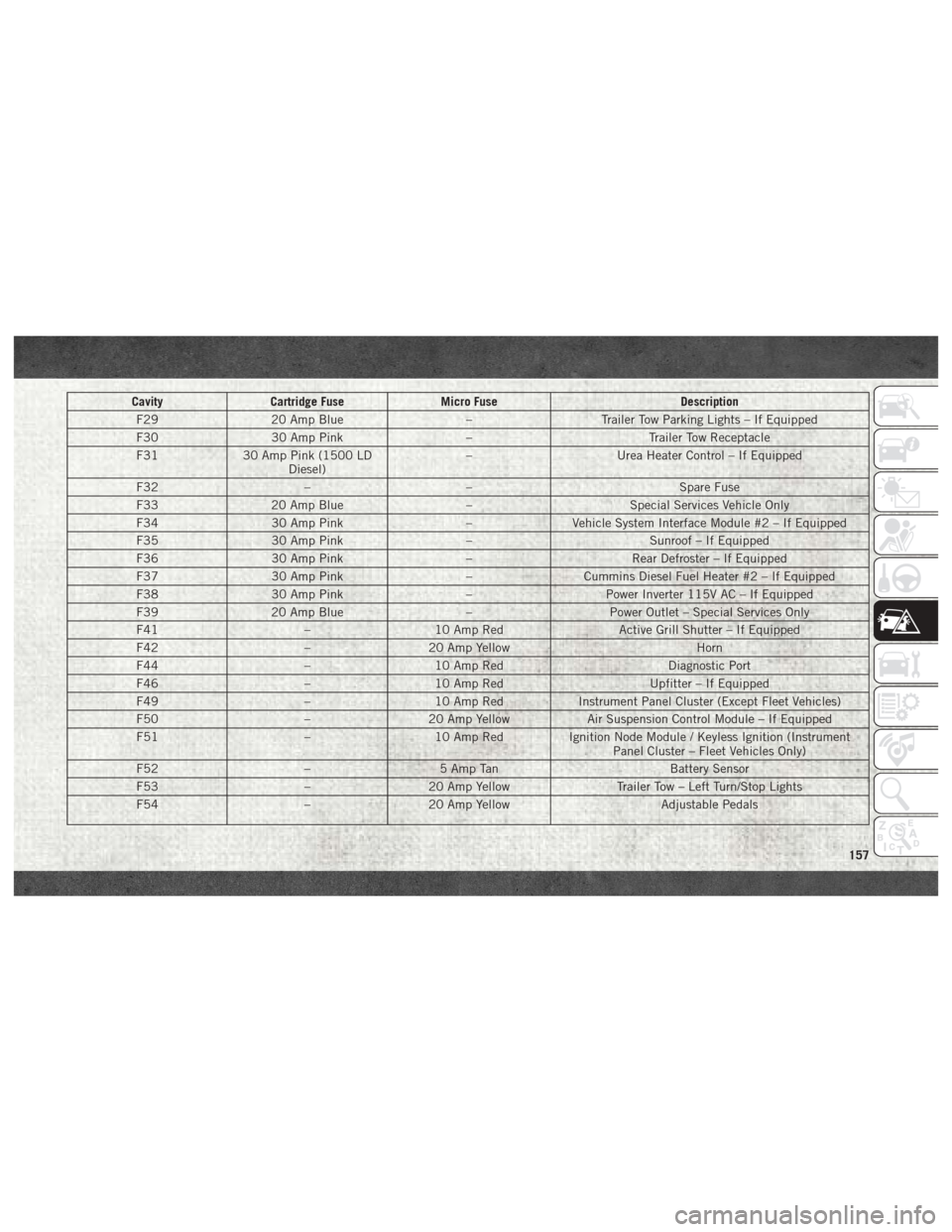
CavityCartridge Fuse Micro Fuse Description
F29 20 Amp Blue –Trailer Tow Parking Lights – If Equipped
F30 30 Amp Pink –Trailer Tow Receptacle
F31 30 Amp Pink (1500 LD
Diesel) –
Urea Heater Control – If Equipped
F32 –– Spare Fuse
F33 20 Amp Blue –Special Services Vehicle Only
F34 30 Amp Pink –Vehicle System Interface Module #2 – If Equipped
F35 30 Amp Pink –Sunroof – If Equipped
F36 30 Amp Pink –Rear Defroster – If Equipped
F37 30 Amp Pink –Cummins Diesel Fuel Heater #2 – If Equipped
F38 30 Amp Pink –Power Inverter 115V AC – If Equipped
F39 20 Amp Blue –Power Outlet – Special Services Only
F41 –10 Amp Red Active Grill Shutter – If Equipped
F42 –20 Amp Yellow Horn
F44 –10 Amp Red Diagnostic Port
F46 –10 Amp Red Upfitter – If Equipped
F49 –10 Amp Red Instrument Panel Cluster (Except Fleet Vehicles)
F50 –20 Amp Yellow Air Suspension Control Module – If Equipped
F51 –10 Amp Red Ignition Node Module / Keyless Ignition (Instrument
Panel Cluster – Fleet Vehicles Only)
F52 –5 Amp Tan Battery Sensor
F53 –20 Amp Yellow Trailer Tow – Left Turn/Stop Lights
F54 –20 Amp Yellow Adjustable Pedals
157
Page 166 of 298

On 3500 models with dual rear wheels
(DRW), you must first remove the hub caps.
The jack handle driver has a hook at one end
that will fit in the pull off notch of the rear
hub caps. Position the hook and pull straight
out on the ratchet firmly. The hub cap should
pop off. The wheel skins can now be re-
moved. For the front hub cap, use the flat
blade on the end of the lug wrench to pull the
caps off. The wheel skin can now be removed.
CAUTION!
• Use a pulling motion to remove the hubcap. Do not use a twisting motion when
removing the hub cap, damage to the
hub cap; finish may occur.
• The rear hub caps on the dual rear wheel
has two pull off notches. Make sure that
the hook of the jack handle driver is
located squarely in the cap notch before
attempting to pull off.
You must use the flat end of the lug wrench to
pull off the wheel skins. Locate the hub cap
pull notches (2 notches on each cap). Insert the flat tip completely and using a back and
forth motion, loosen the wheel skin. Repeat
this procedure around the tire until the skin
pops off.
Replace the wheel skins first using a rubber
mallet. When replacing the hub caps, tilt the
cap retainer over the lug nut bolt circle and
strike the high side down with a rubber mal-
let. Be sure that the hub caps and wheel
skins are firmly seated around the wheel.
JUMP STARTING
If your vehicle has a discharged battery, it can
be jump started using a set of jumper cables
and a battery in another vehicle, or by using a
portable battery booster pack. Jump starting
can be dangerous if done improperly, so
please follow the procedures in this section
carefully.
WARNING!
Do not attempt jump starting if the battery
is frozen. It could rupture or explode and
cause personal injury.
CAUTION!
Do not use a portable battery booster pack
or any other booster source with a system
voltage greater than 12 Volts or damage to
the battery, starter motor, alternator or
electrical system may occur.
NOTE:
When using a portable battery booster pack,
follow the manufacturer's operating instruc-
tions and precautions.
Preparations For Jump Start
The battery in your vehicle is located in the
front of the engine compartment, behind the
left headlight assembly.
IN CASE OF EMERGENCY
164
Page 167 of 298

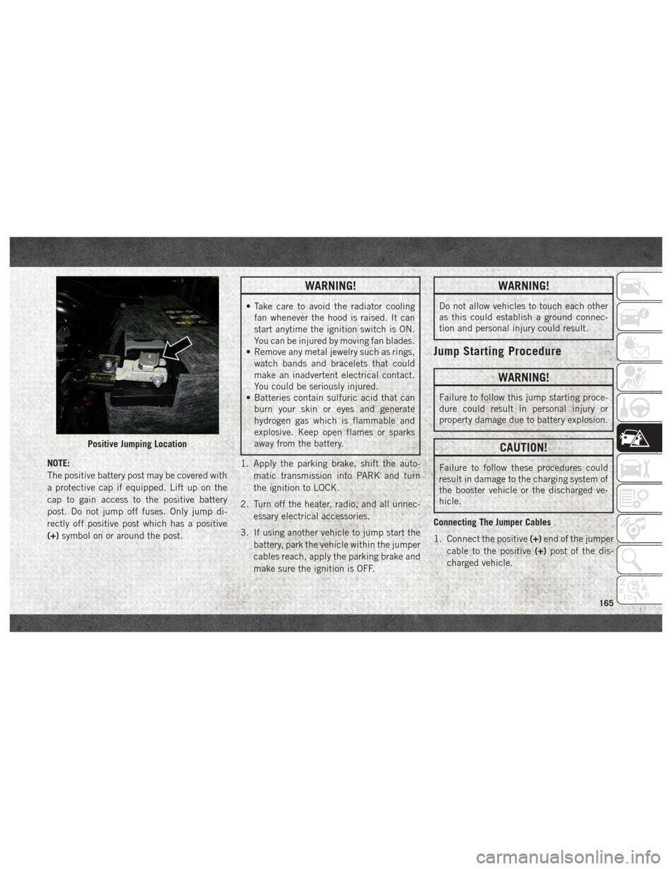
NOTE:
The positive battery post may be covered with
a protective cap if equipped. Lift up on the
cap to gain access to the positive battery
post. Do not jump off fuses. Only jump di-
rectly off positive post which has a positive
(+)symbol on or around the post.
WARNING!
• Take care to avoid the radiator cooling
fan whenever the hood is raised. It can
start anytime the ignition switch is ON.
You can be injured by moving fan blades.
• Remove any metal jewelry such as rings,
watch bands and bracelets that could
make an inadvertent electrical contact.
You could be seriously injured.
• Batteries contain sulfuric acid that can
burn your skin or eyes and generate
hydrogen gas which is flammable and
explosive. Keep open flames or sparks
away from the battery.
1. Apply the parking brake, shift the auto- matic transmission into PARK and turn
the ignition to LOCK.
2. Turn off the heater, radio, and all unnec- essary electrical accessories.
3. If using another vehicle to jump start the battery, park the vehicle within the jumper
cables reach, apply the parking brake and
make sure the ignition is OFF.
WARNING!
Do not allow vehicles to touch each other
as this could establish a ground connec-
tion and personal injury could result.
Jump Starting Procedure
WARNING!
Failure to follow this jump starting proce-
dure could result in personal injury or
property damage due to battery explosion.
CAUTION!
Failure to follow these procedures could
result in damage to the charging system of
the booster vehicle or the discharged ve-
hicle.
Connecting The Jumper Cables
1. Connect the positive (+)end of the jumper
cable to the positive (+)post of the dis-
charged vehicle.
Positive Jumping Location
165
Page 168 of 298

NOTE:
Do not jump off fuses. Only jump directly off
positive post.
2. Connect the opposite end of the positive (+) jumper cable to the positive (+)post of
the booster battery.
3. Connect the negative (-)end of the jumper
cable to the negative (-)post of the
booster battery.
4. Connect the opposite end of the negative (-)jumper cable to a good engine ground
(exposed metal part of the discharged
vehicle’s engine) away from the battery
and the fuel injection system.
WARNING!
Do not connect the jumper cable to the
negative (-) post of the discharged battery.
The resulting electrical spark could cause
the battery to explode and could result in
personal injury. Only use the specific
ground point, do not use any other exposed
metal parts. 5. Start the engine in the vehicle that has
the booster battery, let the engine idle a
few minutes, and then start the engine in
the vehicle with the discharged battery.
CAUTION!
Do not connect jumper cable to any of the
fuses on the positive battery terminal. The
resulting electrical current will blow the
fuse.
6. Once the engine is started, remove the jumper cables in the reverse sequence:
Disconnecting The Jumper Cables
1. Disconnect the negative (-)end of the
jumper cable from the engine ground of
the vehicle with the discharged battery.
2. Disconnect the opposite end of the nega- tive (-)jumper cable from the negative (-)
post of the booster battery.
3. Disconnect the positive (+)end of the
jumper cable from the positive (+)post of
the booster battery. 4. Disconnect the opposite end of the posi-
tive (+)jumper cable from the positive (+)
post of the vehicle with the discharged
battery.
If frequent jump starting is required to start
your vehicle you should have the battery and
charging system inspected at an authorized
dealer.
CAUTION!
Accessories plugged into the vehicle
power outlets draw power from the vehi-
cle’s battery, even when not in use (i.e.,
cellular devices, etc.). Eventually, if
plugged in long enough without engine
operation, the vehicle’s battery will dis-
charge sufficiently to degrade battery life
and/or prevent the engine from starting.
IF YOUR ENGINE OVERHEATS
In any of the following situations, you can
reduce the potential for overheating by taking
the appropriate action.
• On the highways — slow down.
IN CASE OF EMERGENCY
166
Page 171 of 298

TOWING A DISABLED VEHICLE
This section describes procedures for towing
a disabled vehicle using a commercial towing
service. If the transmission and drivetrain areoperable, disabled vehicles may also be
towed as described under “Recreational Tow-
ing” in the “Starting And Operating” section.
Towing Condition
Wheels OFF The
Ground 2WD Models
4WD Models
Flat Tow NONE If transmission is operable:
• Transmission in
NEUTRAL
• 30 mph (48 km/h) max speed
• 15 miles (24 km) maxdistance See instructions in “Recreational Towing” under
“Starting And Operating”
• Auto Transmission in
PARK
• Manual Transmission in gear ( NOTNEUTRAL)
• Transfer Case in NEUTRAL
•Towinforward direction
Wheel Lift Or Dolly Tow Front
NOT ALLOWED
Rear OK NOT ALLOWED
Flatbed ALL
BEST METHOD BEST METHOD
Proper towing or lifting equipment is required
to prevent damage to your vehicle. Use only
tow bars and other equipment designed for
this purpose, following equipment manufac-
turer’s instructions. Use of safety chains is
mandatory. Attach a tow bar or other towing
device to main structural members of thevehicle, not to bumpers or associated brack-
ets. State and local laws regarding vehicles
under tow must be observed.
If you must use the accessories (wipers, de-
frosters, etc.) while being towed, the ignition
must be in the ON/RUN mode, not the ACC
mode.If the key fob is unavailable or the vehicle's
battery is discharged, refer to “Gear Selector
Override” in this section for instructions on
shifting the automatic transmission out of
PARK for towing.
169