sensor Ram 4500 Chassis Cab 2018 Owner's Manual
[x] Cancel search | Manufacturer: RAM, Model Year: 2018, Model line: 4500 Chassis Cab, Model: Ram 4500 Chassis Cab 2018Pages: 298, PDF Size: 5.88 MB
Page 138 of 298
PARKSENSE FRONT AND REAR PARK
ASSIST — IF EQUIPPED
The ParkSense Park Assist system provides
visual and audible indications of the distance
between the rear and/or front fascia and a
detected obstacle when backing up or mov-
ing forward, e.g. during a parking maneuver.
Refer to “ParkSense System Usage
Precautions” in the Owner’s Manual at
www.mopar.com/en-us/care/
owners-manual.html (U.S. Residents) or
www.owners.mopar.ca (Canadian Residents)
for limitations of this system and recommen-
dations.
ParkSense will retain the last system state
(enabled or disabled) from the last ignition
cycle when the ignition is changed to the
ON/RUN position.
ParkSense can be active only when the gear
selector is in REVERSE or DRIVE. If
ParkSense is enabled at one of these gear
selector positions, the system will remain
active until the vehicle speed is increased to
approximately 7 mph (11 km/h) or above. A
warning will appear in the instrument clusterdisplay indicating the vehicle is above
ParkSense operating speed. The system will
become active again if the vehicle speed is
decreased to speeds less than approximately
6 mph (9 km/h).
ParkSense Sensors
For the 3500, 4500 and 5500 Chassis Cab
vehicles, the rear ParkSense sensors are
shipped loose. Please refer to the Ram Body
Builders Guide for more information.
Cleaning The ParkSense System
Clean the ParkSense sensors with water, car
wash soap and a soft cloth. Do not use rough
or hard cloths. Do not scratch or poke the
sensors. Otherwise, you could damage the
sensors.
PARKVIEW REAR BACK UP CAMERA
— IF EQUIPPED
Your vehicle may be equipped with the
ParkView Rear Back Up Camera that allows
you to see a image of the rear surroundings of
your vehicle whenever the gear selector is put
into REVERSE or whenever it is initiated through the "Backup Camera" button in the
"Controls" menu. Whenever the gear selector
is put into REVERSE, the image will be
displayed in the rearview mirror display (if
equipped) or Uconnect screen (if equipped)
along with a caution note to “check entire
surroundings” across the top of the screen.
After five seconds this note will disappear.
NOTE:
For the 3500, 4500 and 5500 Chassis Cab
vehicles, the Rear Backup Camera is shipped
loose and not installed. Please refer to the
Ram Body Builders Guide for more informa-
tion.
The ParkView Camera is located to the left of
the tailgate handle.
When the vehicle is shifted out of REVERSE
(with Camera delay turned off), the rear Cam-
era mode is exited and the navigation or
audio screen appears again.
When the vehicle is shifted out of REVERSE
(with Camera delay turned on), the rear Cam-
era image will be displayed for up to 10 sec-
onds after shifting out of REVERSE unless
STARTING AND OPERATING
136
Page 142 of 298
The DEF injection system consists of the
following components:
• DEF tank
• DEF pump
• DEF injector
• Electronically-heated DEF lines
• DEF control module
• NOx sensors
• Temperature sensors
• SCR catalyst
• UQS Sensor
Refer to “Instrument Cluster Display” in
“Getting To Know Your Instrument Panel” for
system messages and warnings.
NOTE:
• Your vehicle is equipped with a DEF injec-tion system. You may occasionally hear an
audible clicking noise. This is normal op-
eration.
• The DEF pump will run for a period of time after engine shutdown to purge the DEF
system. This is normal operation.Diesel Exhaust Fluid Storage
Diesel Exhaust Fluid (DEF) is considered a
very stable product with a long shelf life. If
DEF is kept in temperatures between 10° and
90°F (-12° and 32°C), it will last a minimum
of one year.
DEF is subject to freezing at the lowest tem-
peratures. For example, DEF may freeze at
temperatures at or below 12° F (-11° C). The
system has been designed to operate in this
environment.
NOTE:
When working with DEF, it is important to
know that:
• Any containers or parts that come into con-tact with DEF must be DEF compatible
(plastic or stainless steel). Copper, brass,
aluminum, iron or non-stainless steel
should be avoided as they are subject to
corrosion by DEF.
• If DEF is spilled, it should be wiped up completely.
Adding Diesel Exhaust Fluid
The DEF gauge (located on the instrument
cluster) will display the level of DEF remain-
ing in the tank. Refer to “Instrument Cluster”
and “Instrument Cluster Descriptions” in
“Getting To Know Your Instrument Panel” for
further information.
NOTE:
• Driving conditions (altitude, vehicle speed,load, etc.) will effect the amount of DEF
that is used in your vehicle.
• Another factor is that outside temperature can affect DEF consumption. In cold con-
ditions, 12° F (-11° C) and below, the DEF
gauge needle can stay on a fixed position
and may not move for extended periods of
time. This is a normal function of the sys-
tem.
• There is an electric heater inside the DEF tank that automatically works when neces-
sary. And if the DEF supply does freeze, the
truck will operate normally until it thaws.
STARTING AND OPERATING
140
Page 159 of 298
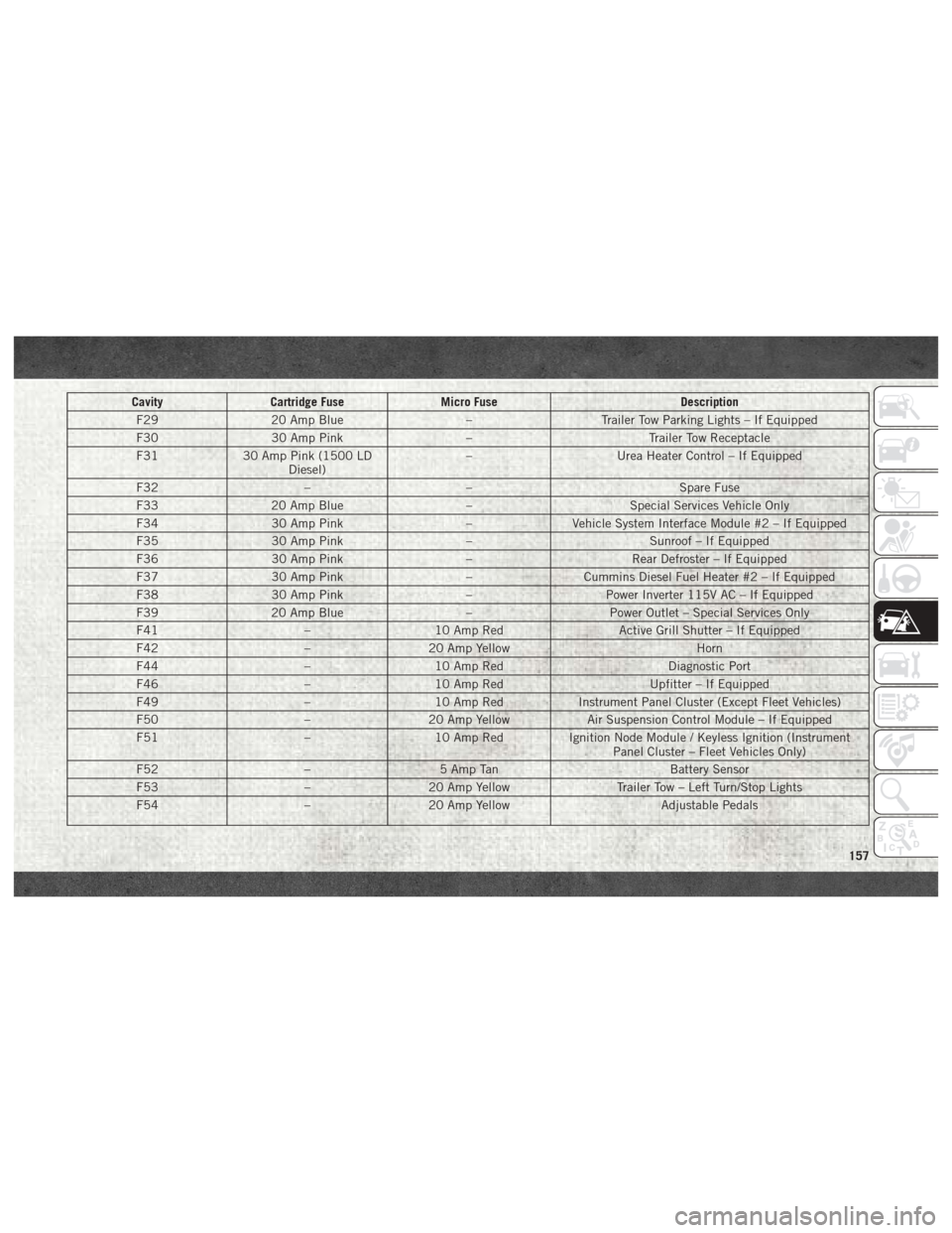
CavityCartridge Fuse Micro Fuse Description
F29 20 Amp Blue –Trailer Tow Parking Lights – If Equipped
F30 30 Amp Pink –Trailer Tow Receptacle
F31 30 Amp Pink (1500 LD
Diesel) –
Urea Heater Control – If Equipped
F32 –– Spare Fuse
F33 20 Amp Blue –Special Services Vehicle Only
F34 30 Amp Pink –Vehicle System Interface Module #2 – If Equipped
F35 30 Amp Pink –Sunroof – If Equipped
F36 30 Amp Pink –Rear Defroster – If Equipped
F37 30 Amp Pink –Cummins Diesel Fuel Heater #2 – If Equipped
F38 30 Amp Pink –Power Inverter 115V AC – If Equipped
F39 20 Amp Blue –Power Outlet – Special Services Only
F41 –10 Amp Red Active Grill Shutter – If Equipped
F42 –20 Amp Yellow Horn
F44 –10 Amp Red Diagnostic Port
F46 –10 Amp Red Upfitter – If Equipped
F49 –10 Amp Red Instrument Panel Cluster (Except Fleet Vehicles)
F50 –20 Amp Yellow Air Suspension Control Module – If Equipped
F51 –10 Amp Red Ignition Node Module / Keyless Ignition (Instrument
Panel Cluster – Fleet Vehicles Only)
F52 –5 Amp Tan Battery Sensor
F53 –20 Amp Yellow Trailer Tow – Left Turn/Stop Lights
F54 –20 Amp Yellow Adjustable Pedals
157
Page 160 of 298
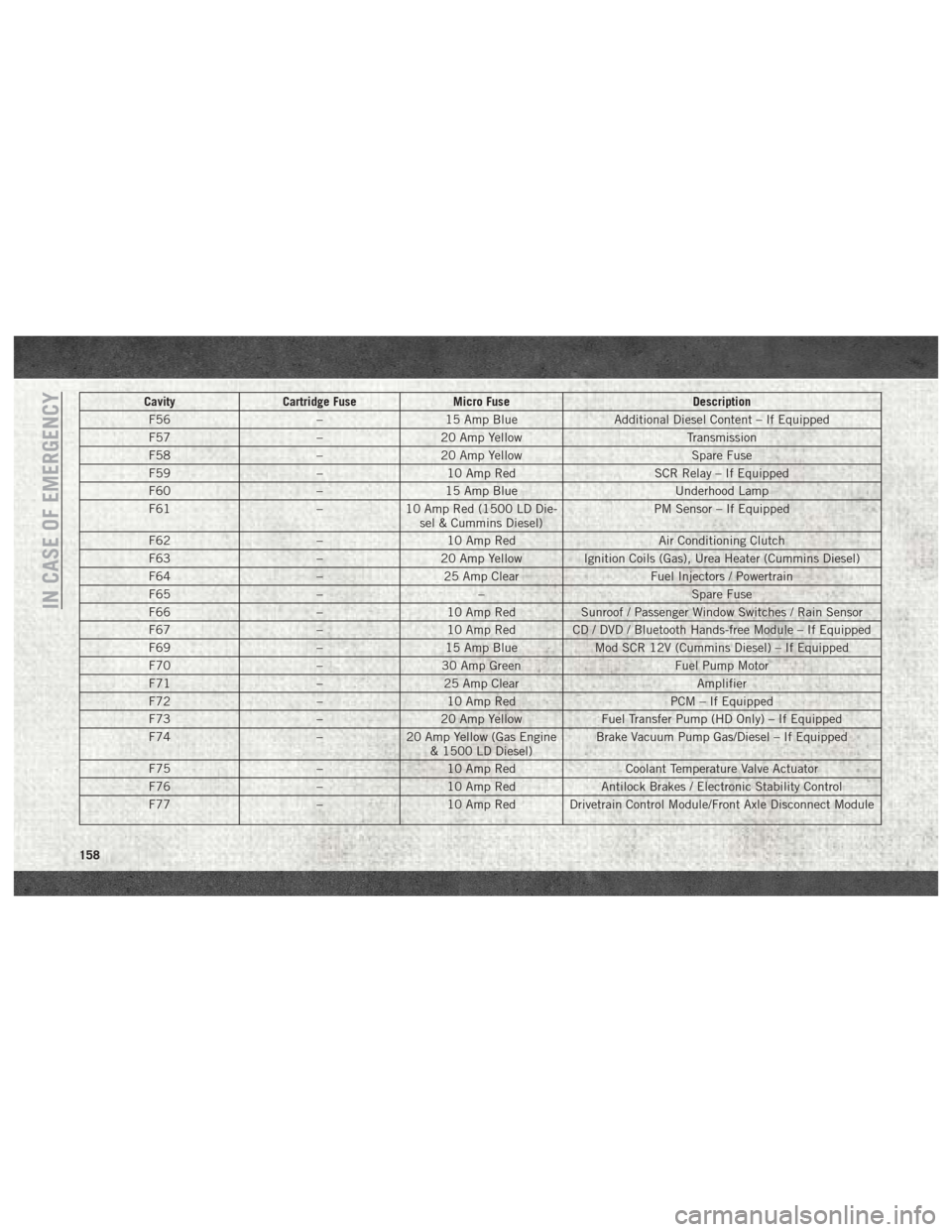
CavityCartridge Fuse Micro Fuse Description
F56 –15 Amp Blue Additional Diesel Content – If Equipped
F57 –20 Amp Yellow Transmission
F58 –20 Amp Yellow Spare Fuse
F59 –10 Amp Red SCR Relay – If Equipped
F60 –15 Amp Blue Underhood Lamp
F61 –10 Amp Red (1500 LD Die-
sel & Cummins Diesel) PM Sensor – If Equipped
F62 –10 Amp Red Air Conditioning Clutch
F63 –20 Amp Yellow Ignition Coils (Gas), Urea Heater (Cummins Diesel)
F64 –25 Amp Clear Fuel Injectors / Powertrain
F65 –– Spare Fuse
F66 –10 Amp Red Sunroof / Passenger Window Switches / Rain Sensor
F67 –10 Amp Red CD / DVD / Bluetooth Hands-free Module – If Equipped
F69 –15 Amp Blue Mod SCR 12V (Cummins Diesel) – If Equipped
F70 –30 Amp Green Fuel Pump Motor
F71 –25 Amp Clear Amplifier
F72 –10 Amp Red PCM – If Equipped
F73 –20 Amp Yellow Fuel Transfer Pump (HD Only) – If Equipped
F74 –20 Amp Yellow (Gas Engine
& 1500 LD Diesel) Brake Vacuum Pump Gas/Diesel – If Equipped
F75 –10 Amp Red Coolant Temperature Valve Actuator
F76 –10 Amp Red Antilock Brakes / Electronic Stability Control
F77 –10 Amp Red Drivetrain Control Module/Front Axle Disconnect Module
IN CASE OF EMERGENCY
158
Page 189 of 298
If the vehicle experiences a sudden loss of
engine power while being driven in heavy
snow or rain, or when plowing snow, and/or
the “SERVICE AIR FILTER” message is dis-
played on the instrument cluster along with a
chime that repeats every 60 seconds, visually
inspect the air filter for snow/ice build up or
extreme water saturation. If the air filter is
not damaged, remove all snow/ice and rein-
stall air filter. If the air filter is damaged,
replace filter element.
NOTE:
The air filter housing contains a Mass Air
Flow sensor. This sensor is critical to proper
engine operation and component longevity.
Any damage or modification to this sensor
could result in major engine and/or exhaust
aftertreatment damage. We recommend you
use Mopar brand parts.
Even though your vehicle is equipped with an
Air Filter Monitor, a visual inspection of the
air cleaner filter element is recommended
every 15,000 miles (24,000km) or
12 months – whichever occurs first.Under nocircumstances should the air cleaner filter ele-
ment exceed 30,000 miles (48,000 km) or
24 months, whichever comes first.
CAUTION!
Many aftermarket performance air filter
elements do not adequately filter the air
entering the engine. Use of such filters can
severely damage your engine.
Draining Fuel/Water Separator
Filter
There are two fuel filter assemblies. One is
located on the driver's side of the engine. The
best access to this water drain valve is from
under the hood. The second one is on the
under body, located in front of the rear axle
above the drive shaft on pick-up models. The
Chassis Cab models second filter location is
on the frame behind the front axle. The best
access to this water drain valve is from under
the vehicle.
CAUTION!
• Do not drain the fuel/water separator
filter when the engine is running.
• Diesel fuel will damage blacktop paving
surfaces. Drain the filter into an appro-
priate container.
If water is detected in the water separator
while the engine is running, or while the
ignition switch is in the ON position, the
“Water In Fuel Indicator Light” will illumi-
nate and an audible chime will be heard five
times. At this point you should stop the
engine and drain the water from both of the
filters.
CAUTION!
If the “Water In Fuel Indicator Light” re-
mains on, DO NOT START the engine be-
fore you drain water from the fuel filters to
avoid engine damage.
If the “Water In Fuel Indicator Light” comes
on and a single chime is heard while you are
driving, or with the ignition switch in the ON
187
Page 190 of 298
position, there may be a problem with your
water separator wiring or sensor. See your
authorized dealer for service.
Upon proper draining of the water from both
fuel filters, the “Water In Fuel Indicator
Light” will remain illuminated for approxi-
mately 10 seconds. If the water was drained
while the engine was running, the “Water In
Fuel Indicator Light” may remain on for ap-
proximately three minutes.
NOTE:
Care should be taken in disposing of used
fluids from your vehicle. Used fluids, indis-
criminately discarded, can present a problem
to the environment. Contact an authorized
dealer, service station, or government agency
for advice on recycling programs and for
where used fluids and filters can be properly
disposed of in your area.
Drain the fuel/water separator filters when
the “Water In Fuel Indicator Light” is ON.
Within 10 minutes of vehicle shutdown, turn
the engine mounted filter drain valve (located
on the side of the filter assembly) counter-
clockwise 1/4 turn, and turn the under body
mounted filter drain valve (located on thebottom of the filter assembly) counterclock
wise 1 full turn. Then turn the ignition switch
to the ON position, and allow any accumu-
lated water to drain. Leave the drain valve
open until all water and contaminants have
been removed. When clean fuel is visible,
close the drain valves by turning them fully
clockwise, and turn the ignition switch to
OFF.
If more than a couple ounces/milliliters of
fuel have been drained, follow the directions
for “Priming If The Engine Has Run Out Of
Fuel.”
Engine Mounted Fuel Filter
Replacement
NOTE:
• Using a fuel filter that does not meet the
manufacturer's filtration and water separat-
ing requirements can severely impact fuel
system life and reliability.
• The engine mounted filter housing is equipped with a No-Filter-No-Run (NFNR)
feature. Engine will not run if:
1. No filter is installed. 2. Inferior/Non-approved filter is used.
Use of OEM filter is required to ensure
vehicle will run.
CAUTION!
• Diesel fuel will damage blacktop pavingsurfaces. Drain the filter into an appro-
priate container.
• Do not prefill the fuel filter when install-
ing a new fuel filter. There is a possibility
debris could be introduced into the fuel
filter during this action. It is best to
install the filter dry and allow the in-tank
lift pump to prime the fuel system.
1. Ensure engine is turned off.
2. Place drain pan under the fuel filter drain hose.
3. Open the water drain valve 1/4 turn coun- terclockwise and completely drain fuel
and water into the approved container.
4. Close the water drain valve.
5. Remove lid using a socket or strap wrench. Rotate counterclockwise for re-
moval. Remove used o-ring and discard it.
SERVICING AND MAINTENANCE
188
Page 191 of 298
6. Remove the used filter cartridge from thehousing and dispose of according to your
local regulations.
7. Wipe clean the sealing surfaces of the lid and housing.
8. Install new o-ring back into ring groove on the filter housing and lubricate with clean
engine oil.
9. Remove new filter cartridge from plastic bag and install into housing.
NOTE:
Do not remove cartridge from bag until
you reach this step in order to keep car-
tridge clean.
10. Push down on the cartridge to ensure it is properly seated. Do not pre-fill the filter
housing with fuel.
11. Install lid onto housing and tighten to 22.5 ft lbs (30.5 N.m). Do not over-
tighten the lid.
12. Prime the engine using the procedure in “Priming If The Engine Has Run Out Of
Fuel.” Then start the engine and confirm
there are no leaks.Underbody Mounted Fuel Filter
Replacement
NOTE:
• Using a fuel filter that does not meet themanufacturer's filtration and water separat-
ing requirements can severely impact fuel
system life and reliability.
• The underbody mounted filter housing will cause the engine not to run if:
1. No filter is installed.
CAUTION!
• Diesel fuel will damage blacktop paving surfaces. Drain the filter into an appro-
priate container.
• Do not prefill the fuel filter when install-
ing a new fuel filter. There is a possibility
debris could be introduced into the fuel
filter during this action. It is best to
install the filter dry and allow the in-tank
lift pump to prime the fuel system.
1. Ensure engine is turned off. 2. Place drain pan under the fuel filter drain
hose.
3. Open the water drain valve 1 full turn counterclockwise and completely drain
fuel and water into the approved
container.
4. Close the water drain valve.
5. Remove lid using a socket or strap wrench. Rotate counterclockwise for re-
moval. Remove used o-ring and discard it.
6. Remove the used filter cartridge from the housing and dispose of according to your
local regulations.
7. Wipe clean the sealing surfaces of the lid and housing.
8. Install new o-ring back into ring groove on the filter housing and lubricate with clean
engine oil.
NOTE:
WIF sensor is re-usable. Service kit comes
with new o-ring for filter canister and WIF
sensor.
189
Page 264 of 298
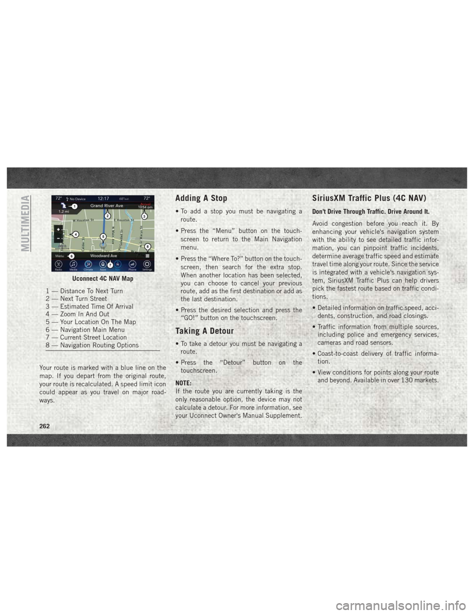
Your route is marked with a blue line on the
map. If you depart from the original route,
your route is recalculated. A speed limit icon
could appear as you travel on major road-
ways.
Adding A Stop
• To add a stop you must be navigating aroute.
• Press the “Menu” button on the touch- screen to return to the Main Navigation
menu.
• Press the “Where To?” button on the touch- screen, then search for the extra stop.
When another location has been selected,
you can choose to cancel your previous
route, add as the first destination or add as
the last destination.
• Press the desired selection and press the “GO!” button on the touchscreen.
Taking A Detour
• To take a detour you must be navigating aroute.
• Press the “Detour” button on the touchscreen.
NOTE:
If the route you are currently taking is the
only reasonable option, the device may not
calculate a detour. For more information, see
your Uconnect Owner's Manual Supplement.
SiriusXM Traffic Plus (4C NAV)
Don't Drive Through Traffic. Drive Around It.
Avoid congestion before you reach it. By
enhancing your vehicle's navigation system
with the ability to see detailed traffic infor-
mation, you can pinpoint traffic incidents,
determine average traffic speed and estimate
travel time along your route. Since the service
is integrated with a vehicle's navigation sys-
tem, SiriusXM Traffic Plus can help drivers
pick the fastest route based on traffic condi-
tions.
• Detailed information on traffic speed, acci- dents, construction, and road closings.
• Traffic information from multiple sources, including police and emergency services,
cameras and road sensors.
• Coast-to-coast delivery of traffic informa- tion.
• View conditions for points along your route and beyond. Available in over 130 markets.
Uconnect 4C NAV Map
1 — Distance To Next Turn
2 — Next Turn Street
3 — Estimated Time Of Arrival
4 — Zoom In And Out
5 — Your Location On The Map
6 — Navigation Main Menu
7 — Current Street Location
8 — Navigation Routing Options
MULTIMEDIA
262