tow Ram 4500 Chassis Cab 2018 Owner's Guide
[x] Cancel search | Manufacturer: RAM, Model Year: 2018, Model line: 4500 Chassis Cab, Model: Ram 4500 Chassis Cab 2018Pages: 298, PDF Size: 5.88 MB
Page 147 of 298

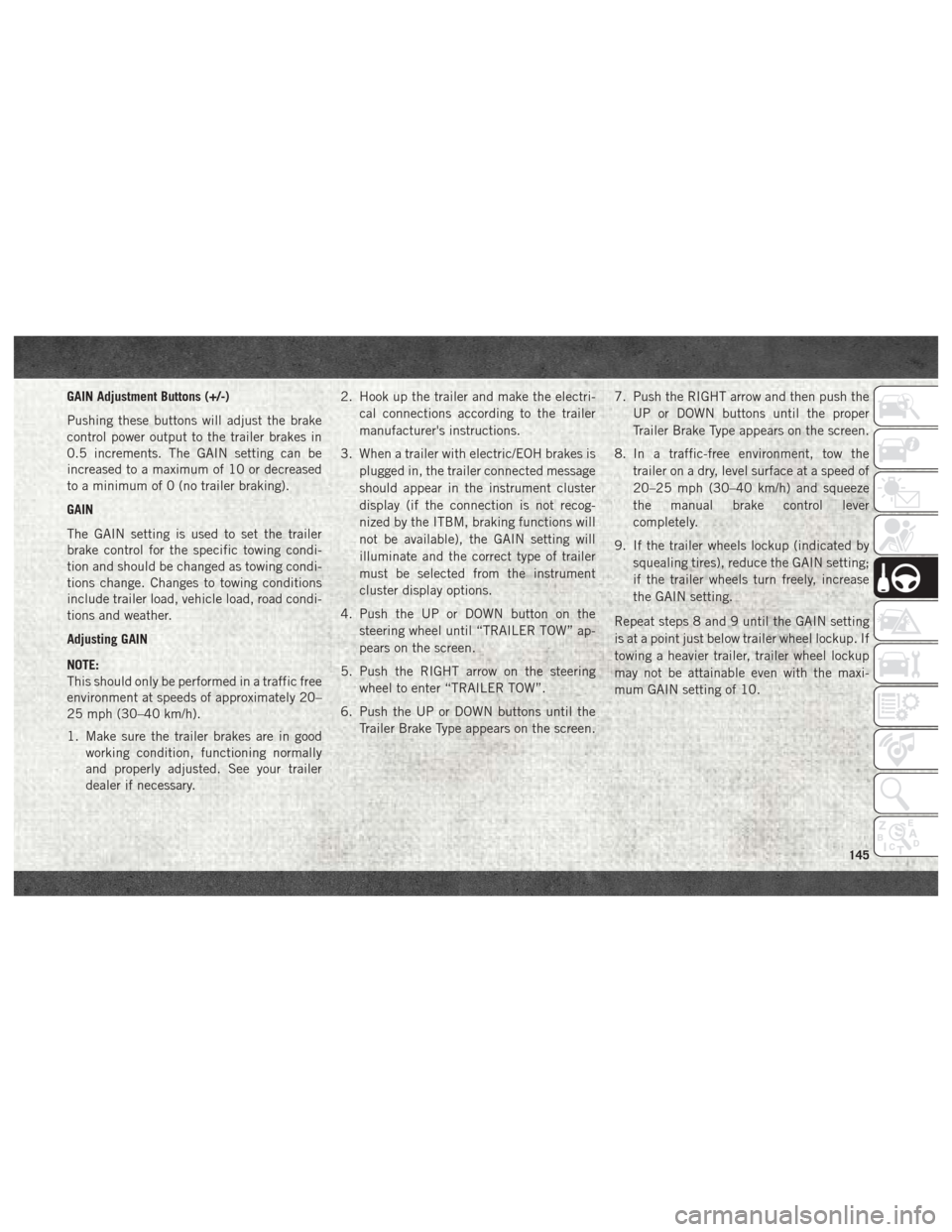
GAIN Adjustment Buttons (+/-)
Pushing these buttons will adjust the brake
control power output to the trailer brakes in
0.5 increments. The GAIN setting can be
increased to a maximum of 10 or decreased
to a minimum of 0 (no trailer braking).
GAIN
The GAIN setting is used to set the trailer
brake control for the specific towing condi-
tion and should be changed as towing condi-
tions change. Changes to towing conditions
include trailer load, vehicle load, road condi-
tions and weather.
Adjusting GAIN
NOTE:
This should only be performed in a traffic free
environment at speeds of approximately 20–
25 mph (30–40 km/h).
1. Make sure the trailer brakes are in goodworking condition, functioning normally
and properly adjusted. See your trailer
dealer if necessary. 2. Hook up the trailer and make the electri-
cal connections according to the trailer
manufacturer's instructions.
3. When a trailer with electric/EOH brakes is plugged in, the trailer connected message
should appear in the instrument cluster
display (if the connection is not recog-
nized by the ITBM, braking functions will
not be available), the GAIN setting will
illuminate and the correct type of trailer
must be selected from the instrument
cluster display options.
4. Push the UP or DOWN button on the steering wheel until “TRAILER TOW” ap-
pears on the screen.
5. Push the RIGHT arrow on the steering wheel to enter “TRAILER TOW”.
6. Push the UP or DOWN buttons until the Trailer Brake Type appears on the screen. 7. Push the RIGHT arrow and then push the
UP or DOWN buttons until the proper
Trailer Brake Type appears on the screen.
8. In a traffic-free environment, tow the trailer on a dry, level surface at a speed of
20–25 mph (30–40 km/h) and squeeze
the manual brake control lever
completely.
9. If the trailer wheels lockup (indicated by squealing tires), reduce the GAIN setting;
if the trailer wheels turn freely, increase
the GAIN setting.
Repeat steps 8 and 9 until the GAIN setting
is at a point just below trailer wheel lockup. If
towing a heavier trailer, trailer wheel lockup
may not be attainable even with the maxi-
mum GAIN setting of 10.
145
Page 149 of 298

RECREATIONAL TOWING (BEHIND MOTORHOME, ETC.)
Towing This Vehicle Behind Another Vehicle
Towing ConditionWheels OFF The
Ground Two-Wheel Drive
Models Four-Wheel Drive Models
Flat Tow NONENOT ALLOWED See Instructions
• Automatic transmission in PARK
• Manual transmission in gear (NOT in NEUTRAL)
• Transfer case in NEUTRAL (N)
• Tow in forward direction
Dolly Tow Front
NOT ALLOWED
NOT ALLOWED
Rear OK NOT ALLOWED
On Trailer ALLOK OK
NOTE:
• When towing your vehicle, always follow
applicable state and provincial laws. Con-
tact state and provincial Highway Safety
offices for additional details.
Recreational Towing —
Two-Wheel Drive Models
DO NOT flat tow this vehicle. Damage to the
drivetrain will result. Recreational towing (for two-wheel drive
models) is allowed
ONLYif the rear wheels are
OFF the ground. This may be accomplished
using a tow dolly or vehicle trailer. If using a
tow dolly, follow this procedure:
1. Properly secure the dolly to the tow ve- hicle, following the dolly manufacturer's
instructions.
2. Drive the rear wheels onto the tow dolly. 3. Firmly apply the parking brake. Place au-
tomatic transmission in PARK, manual
transmission in gear (not in NEUTRAL).
4. Properly secure the rear wheels to the dolly, following the dolly manufacturer's
instructions.
5. Turn the ignition OFF and remove the key fob.
6. Install a suitable clamping device, de- signed for towing, to secure the front
wheels in the straight position.
147
Page 150 of 298

CAUTION!
• Towing with the rear wheels on theground will cause severe transmission
damage. Damage from improper towing
is not covered under the New Vehicle
Limited Warranty.
• Do not disconnect the driveshaft be-
cause fluid may leak from the transmis-
sion, causing damage to internal parts.
Recreational Towing —
Four-Wheel Drive Models
NOTE:
Both the manual shift and electronic shift
transfer cases must be shifted into NEUTRAL
(N) for recreational towing. Automatic trans-
missions must be shifted into PARK for rec-
reational towing. Manual transmissions must
be placed in gear (NOT in NEUTRAL) for
recreational towing. Refer to the following for
the proper transfer case NEUTRAL (N) shift-
ing procedure for your vehicle.
CAUTION!
• DO NOT dolly tow any 4WD vehicle.Towing with only one set of wheels on
the ground (front or rear) will cause
severe transmission and/or transfer case
damage. Tow with all four wheels either
ON the ground, or OFF the ground (using
a vehicle trailer).
• Tow only in the forward direction. Towing
this vehicle backwards can cause severe
damage to the transfer case.
• Before recreational towing, the transfer
case must be in NEUTRAL. To be certain
the transfer case is fully in NEUTRAL,
perform the procedure outlined under
“Shifting Into NEUTRAL”. Internal
transmission damage will result, if the
transfer case is not in NEUTRAL during
towing.
• Automatic transmissions must be
placed in PARK, and manual transmis-
sions must be placed in gear (not in
Neutral) for recreational towing.
• Towing this vehicle in violation of the
above requirements can cause severe
CAUTION!
transmission and/or transfer case dam-
age. Damage from improper towing is
not covered under the New Vehicle Lim-
ited Warranty.
• Do not disconnect the rear driveshaft
because fluid will leak from the transfer
case, causing damage to internal parts.
• Do not use a bumper-mounted clamp-on
tow bar on your vehicle. The bumper
face bar will be damaged.
Shifting Into NEUTRAL (N)
Use the following procedure to prepare your
vehicle for recreational towing.
WARNING!
You or others could be injured or killed if
you leave the vehicle unattended with the
transfer case in the NEUTRAL (N) position
without first fully engaging the parking
brake. The transfer case NEUTRAL (N)
position disengages both the front and rear
driveshafts from the powertrain, and will
allow the vehicle to roll, even if the auto-
STARTING AND OPERATING
148
Page 151 of 298

WARNING!
matic transmission is in PARK (or manual
transmission is in gear). The parking brake
should always be applied when the driver
is not in the vehicle.
CAUTION!
It is necessary to follow these steps to be
certain that the transfer case is fully in
NEUTRAL (N) before recreational towing
to prevent damage to internal parts.
1. Bring the vehicle to a complete stop on level ground, with the engine running.
Firmly apply the parking brake.
2. Shift the transmission to NEUTRAL.
3. Press and hold the brake pedal.
4. Depress the clutch pedal on a manual transmission.
5. Shift the transfer case into NEUTRAL: • With manual shift transfer case, shift
the transfer case lever into NEUTRAL
(N).
• With electronic shift transfer case, push and hold the transfer case NEU-
TRAL (N) button. Some models have a
small, recessed "N" button (at the cen-
ter of the transfer case switches) that
must be pressed using a ballpoint pen
or similar object. Other models have a
rectangular NEUTRAL switch, below
the rotary transfer case control knob.
The NEUTRAL (N) indicator light will
blink while the shift is in progress. The
light will stop blinking (stay on solid)
when the shift to NEUTRAL (N) is com-
plete. After the shift is completed and
the NEUTRAL (N) light stays on, re-
lease the NEUTRAL (N) button.
6. Release the parking brake.
7. Shift the transmission into REVERSE. 8. Release the brake pedal (and clutch pedal
on manual transmissions) for five seconds
and ensure that there is no vehicle
movement.
9. Repeat steps seven and eight with auto- matic transmission in DRIVE or manual
transmission in first gear.
10. Shift the transmission to NEUTRAL. Firmly apply the parking brake. Turn OFF
the engine. For vehicles with Keyless
Enter-N-Go, push and hold the ENGINE
START/STOP button until the engine
shuts off.
11. Shift the transmission into PARK or place manual transmission in gear (NOT
in NEUTRAL).
12. Place the ignition in the OFF mode, and remove the key fob.
13. Attach the vehicle to the tow vehicle using a suitable tow bar.
14. Release the parking brake.
149
Page 152 of 298

NOTE:
With electronic shift transfer case:
• Steps 2 through 4 are requirements thatmust be met before pushing the NEUTRAL
(N) button, and must continue to be met
until the shift has been completed. If any of
these requirements are not met before
pushing the NEUTRAL (N) button or are no
longer met during the shift, the NEUTRAL
(N) indicator light will flash continuously
until all requirements are met or until the
NEUTRAL (N) button is released.
• The ignition must be in the ON/RUN mode for a shift to take place and for the position
indicator lights to be operable. If the igni-
tion is not in the ON/RUN mode, the shift
will not take place and no position indicator
lights will be on or flashing.
• A flashing NEUTRAL (N) position indicator light indicates that shift requirements have
not been met.Shifting Out Of NEUTRAL (N)
Use the following procedure to prepare your
vehicle for normal usage:
1. Bring the vehicle to a complete stop,
leaving it connected to the tow vehicle.
2. Firmly apply the parking brake.
3. Turn the ignition to the ON/RUN mode, but do not start the engine.
4. Press and hold the brake pedal.
5. Shift the transmission into NEUTRAL.
• With manual shift transfer case, shiftthe transfer case lever to the desired
position.
• With electronic shift transfer case with rotary selector switch, push and hold
the transfer case NEUTRAL (N) button
until the NEUTRAL (N) indicator light
turns off. After the NEUTRAL (N) indi-
cator light turns off, release the NEU-
TRAL (N) button. After the NEUTRAL
(N) button has been released, the
transfer case will shift to the position
indicated by the selector switch. • With electronic shift transfer case with
push-button selector switch, push and
hold the switch for the desired transfer
case position, until the NEUTRAL (N)
indicator light turns off and the desired
position indicator light turns on.
NOTE:
When shifting out of transfer case NEUTRAL
(N), the engine should remain OFF to avoid
gear clash.
6. Shift automatic transmission into PARK.
7. Release the brake pedal (and clutch pedal on a manual transmission).
8. Disconnect vehicle from the tow vehicle.
9. Start the engine.
10. Press and hold the brake pedal.
11. Release the parking brake.
12. Shift the transmission into gear, release the brake pedal (and clutch pedal on
manual transmissions), and check that
the vehicle operates normally.
STARTING AND OPERATING
150
Page 155 of 298

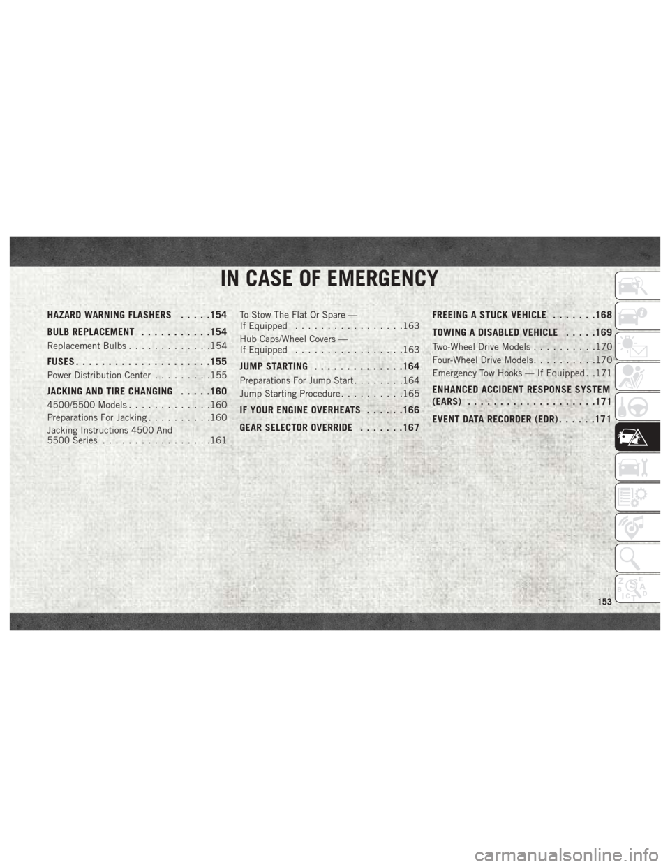
IN CASE OF EMERGENCY
HAZARD WARNING FLASHERS.....154
BULB REPLACEMENT ...........154
Replacement Bulbs.............154
FUSES.................... .155
Power Distribution Center.........155
JACKING AND TIRE CHANGING .....160
4500/5500 Models.............160
Preparations For Jacking ..........160
Jacking Instructions 4500 And
5500 Series .................161 To Stow The Flat Or Spare —
If Equipped
.................163
Hub Caps/Wheel Covers —
If Equipped .................163
JUMP STARTING ..............164
Preparations For Jump Start ........164
Jump Starting Procedure ..........165
IF YOUR ENGINE OVERHEATS ......166
GEAR SELECTOR OVERRIDE .......167FREEING A STUCK VEHICLE
.......168
TOWING A DISABLED VEHICLE .....169
Two-Wheel Drive Models..........170
Four-Wheel Drive Models ..........170
Emergency Tow Hooks — If Equipped . .171
ENHANCED ACCIDENT RESPONSE SYSTEM
(EARS) ................... .171
EVENT DATA RECORDER (EDR) ......171
IN CASE OF EMERGENCY
153
Page 158 of 298

CavityCartridge Fuse Micro Fuse Description
F09 40 Amp Green (Special
Services Vehicle & Cum- mins Diesel) –
Diesel Fuel Heater – If Equipped
F10 40 Amp Green –Body Controller / Exterior Lighting #2
F10 50 Amp Red –Body Controller / Exterior Lighting #2 – If Equipped with
Stop/Start
F11 30 Amp Pink –Integrated Trailer Brake Module – If Equipped
F12 40 Amp Green –Body Controller #3 / Power Locks
F13 40 Amp Green – Blower Motor
F14 40 Amp Green –Body Controller #4 / Interior Lighting
F16 30 Amp Pink –Smart Bar – If Equipped
F19 20 Amp Blue (1500 LD
Diesel)
30 Amp Pink (Cummins Diesel) –
SCR – If Equipped
F20 30 Amp Pink –Passenger Door Module
F21 30 Amp Pink –Drive Train Control Module
F22 20 Amp Blue
30 Amp Pink (Cummins Diesel) –
Engine Control Module
F23 30 Amp Pink –Body Controller #1 / Interior Lighting
F24 30 Amp Pink –Driver Door Module
F25 30 Amp Pink – Front Wiper
F26 30 Amp Pink –Antilock Brakes / Stability Control Module / Valves
F28 20 Amp Blue –Trailer Tow Backup Lights – If Equipped
IN CASE OF EMERGENCY
156
Page 159 of 298

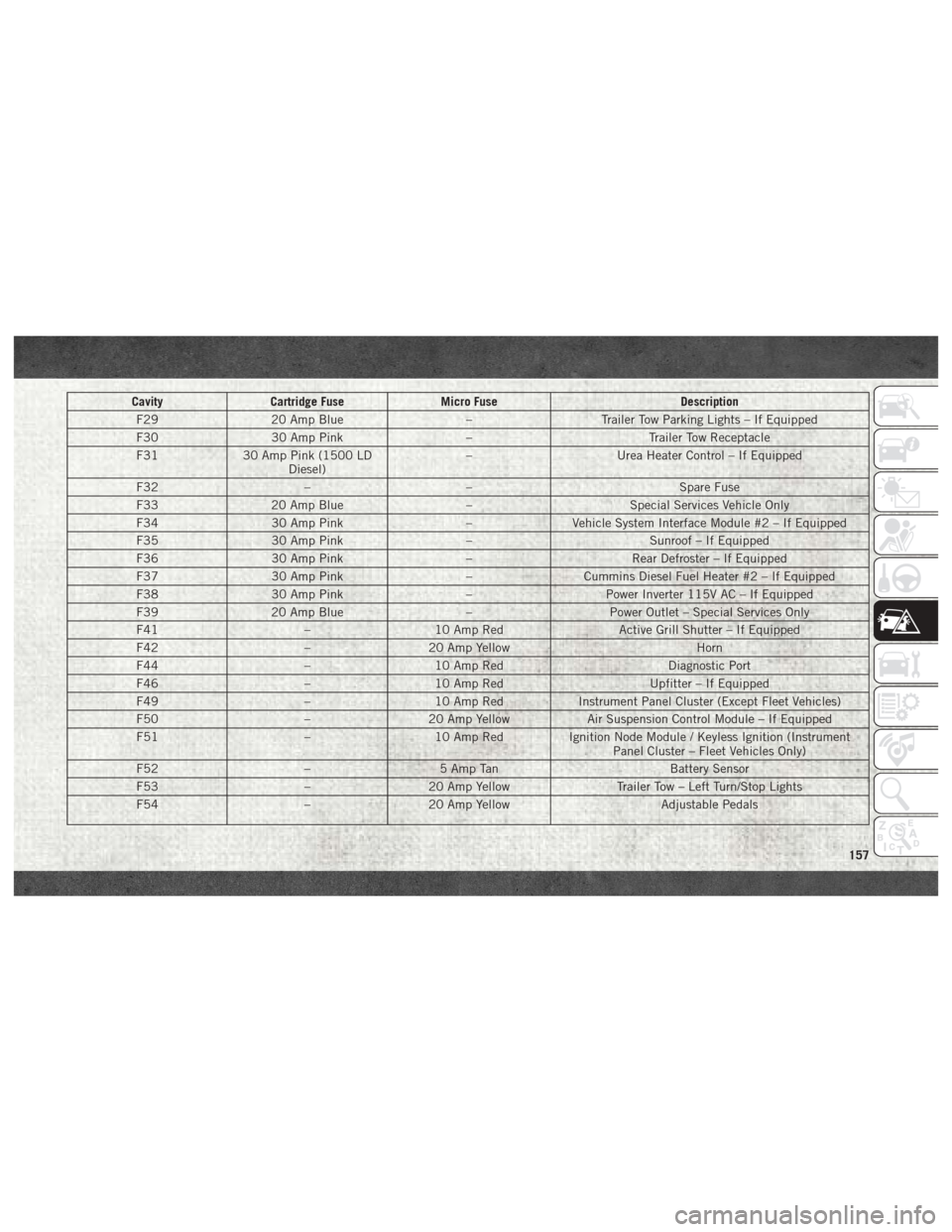
CavityCartridge Fuse Micro Fuse Description
F29 20 Amp Blue –Trailer Tow Parking Lights – If Equipped
F30 30 Amp Pink –Trailer Tow Receptacle
F31 30 Amp Pink (1500 LD
Diesel) –
Urea Heater Control – If Equipped
F32 –– Spare Fuse
F33 20 Amp Blue –Special Services Vehicle Only
F34 30 Amp Pink –Vehicle System Interface Module #2 – If Equipped
F35 30 Amp Pink –Sunroof – If Equipped
F36 30 Amp Pink –Rear Defroster – If Equipped
F37 30 Amp Pink –Cummins Diesel Fuel Heater #2 – If Equipped
F38 30 Amp Pink –Power Inverter 115V AC – If Equipped
F39 20 Amp Blue –Power Outlet – Special Services Only
F41 –10 Amp Red Active Grill Shutter – If Equipped
F42 –20 Amp Yellow Horn
F44 –10 Amp Red Diagnostic Port
F46 –10 Amp Red Upfitter – If Equipped
F49 –10 Amp Red Instrument Panel Cluster (Except Fleet Vehicles)
F50 –20 Amp Yellow Air Suspension Control Module – If Equipped
F51 –10 Amp Red Ignition Node Module / Keyless Ignition (Instrument
Panel Cluster – Fleet Vehicles Only)
F52 –5 Amp Tan Battery Sensor
F53 –20 Amp Yellow Trailer Tow – Left Turn/Stop Lights
F54 –20 Amp Yellow Adjustable Pedals
157
Page 161 of 298

CavityCartridge Fuse Micro Fuse Description
F78 –10 Amp Red Engine Control Module / Electric Power Steering
F79 –15 Amp Blue Clearance Lights
F80 –10 Amp Red Universal Garage Door Opener / Compass
F81 –20 Amp Yellow Trailer Tow Right Turn / Stop Lights
F82 –10 Amp Red Steering Column Control Module / Cruise Control
F84 –15 Amp Blue Switch Bank / Instrument Cluster
F85 –10 Amp Red Airbag Module
F86 –10 Amp Red Airbag Module
F87 –10 Amp Red Air Suspension – If Equipped / Trailer Tow / Steering Col-
umn Control Module
F88 –15 Amp Blue Instrument Panel Cluster
F90/F91 –20 Amp Yellow Power Outlet (Rear Seats) Customer Selectable
F93 –20 Amp Yellow Cigar Lighter
F94 –10 Amp Red Shifter / Transfer Case Module
F95 –10 Amp Red Rear Camera / Park Assist
F96 –10 Amp Red Rear Seat Heater Switch
F97 –25 Amp Clear Rear Heated Seats & Heated Steering Wheel – If
Equipped
F98 –25 Amp Clear Front Heated Seats – If Equipped
F99 –10 Amp Red Climate Control
F100 –10 Amp Red Upfitters – If Equipped
F101 –15 Amp Blue Electrochromatic Mirror / Smart High Beams – If
Equipped
F104 –20 Amp Yellow Power Outlets (Instrument Panel / Center Console)
159
Page 163 of 298

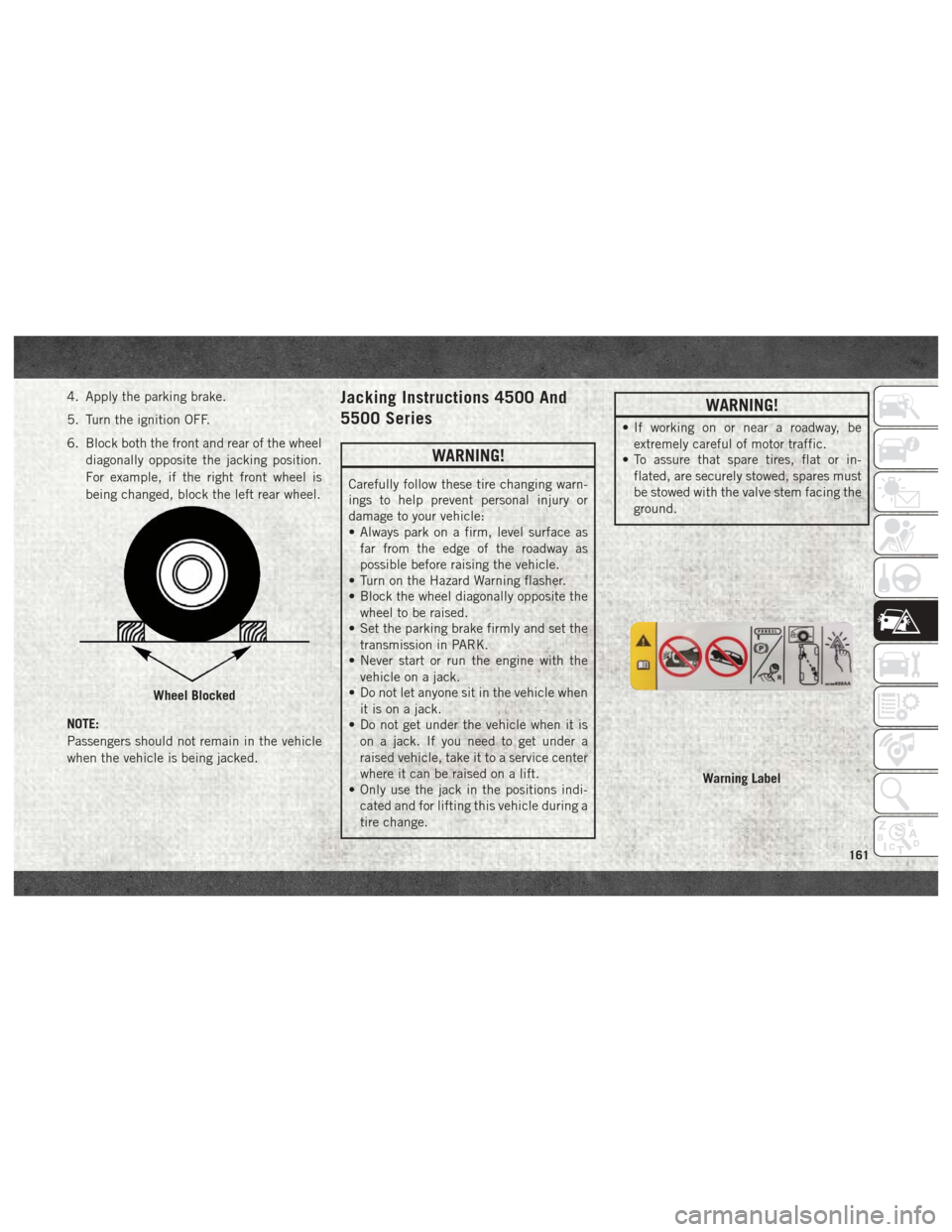
4. Apply the parking brake.
5. Turn the ignition OFF.
6. Block both the front and rear of the wheeldiagonally opposite the jacking position.
For example, if the right front wheel is
being changed, block the left rear wheel.
NOTE:
Passengers should not remain in the vehicle
when the vehicle is being jacked.Jacking Instructions 4500 And
5500 Series
WARNING!
Carefully follow these tire changing warn-
ings to help prevent personal injury or
damage to your vehicle:
• Always park on a firm, level surface as far from the edge of the roadway as
possible before raising the vehicle.
• Turn on the Hazard Warning flasher.
• Block the wheel diagonally opposite the
wheel to be raised.
• Set the parking brake firmly and set the
transmission in PARK.
• Never start or run the engine with the
vehicle on a jack.
• Do not let anyone sit in the vehicle when
it is on a jack.
• Do not get under the vehicle when it is
on a jack. If you need to get under a
raised vehicle, take it to a service center
where it can be raised on a lift.
• Only use the jack in the positions indi-
cated and for lifting this vehicle during a
tire change.
WARNING!
• If working on or near a roadway, beextremely careful of motor traffic.
• To assure that spare tires, flat or in-
flated, are securely stowed, spares must
be stowed with the valve stem facing the
ground.
Wheel Blocked
Warning Label
161