ESP Ram 4500 Chassis Cab 2018 User Guide
[x] Cancel search | Manufacturer: RAM, Model Year: 2018, Model line: 4500 Chassis Cab, Model: Ram 4500 Chassis Cab 2018Pages: 298, PDF Size: 5.88 MB
Page 2 of 298

This guide has been prepared to help you get quickly acquainted with your new RAM brand vehicle
and to provide a convenient reference source for common questions. Howev\
er, it is not a substitute for your Owner’s Manual.
For complete operational instructions, maintenance procedures and import\
ant safety messages, please consult your Owner’s Manual, Navigation/Uconnect manuals found on the website on the back c\
over and
other Warning Labels in your vehicle.
Not all features shown in this guide may apply to your vehicle. For addi\
tional information on accessories
to help personalize your vehicle, visit www.mopar.com (U.S.), www.mopar.ca (Canada) or your local
RAM brand dealer.
DRIVING AND ALCOHOL
Drunken driving is one of the most frequent causes of collisions. Your driving ability can
be seriously impaired with blood alcohol levels far below the legal mini\
mum. If you are drinking, don’t
drive. Ride with a designated non-drinking driver, call a cab, a friend, or use public transportation.
WARNING
Driving after drinking can lead to a collision. Your perceptions are less sharp, your reflexes are slower,
and your judgment is impaired when you have been drinking. Never drink a\
nd then drive.
IMPORTANT
Get warranty and other information online – you can review and print \
or download a copy of the Owner’s Manual, Navigation/Uconnect manuals and the limited warranties provided by FCA US LLC for your
vehicle by visiting www.mopar.com (U.S.) or www.owners.mopar.ca (Canada). Click on the applicable
link in the “Popular Topics” area of the www.mopar.com (U.S.) or www.owners.mopar.ca (Canada)
homepage and follow the instructions to select the applicable year, make and model of your vehicle.
This User Guide is intended to familiarize you with the important featur\
es of your vehicle. Your Owner’s Manual, Navigation/Uconnect manuals and Warranty Booklet can be found by visiting the website on the
back cover of your User Guide. We hope you find these resources useful. U.S. residents can purchase
replacement kits by visiting www.techauthority.com and Canadian residents can purchase replacement
kits by calling 1 800 387-1143.
The driver’s primary responsibility is the safe operation of the vehicle. Driving while distracted can result in loss of vehicle control, resulting in a collision and personal injury. FCA US LLC strongly recommends that the
driver use extreme caution when using any device or feature that may tak\
e their attention off the road. Use of
any electrical devices, such as cellular telephones, computers, portable\
radios, vehicle navigation or other devices, by the driver while the vehicle is moving is dangerous and coul\
d lead to a serious collision. Texting while driving is also dangerous and should never be done while the vehic\
le is moving. If you find yourself
unable to devote your full attention to vehicle operation, pull off the \
road to a safe location and stop your
vehicle. Some states or provinces prohibit the use of cellular telephone\
s or texting while driving. It is always the driver’s responsibility to comply with all local laws.
3112190_18b_Ram_ChassisCab_UG_070617.indd 27/6/17 2:58 PM
Page 3 of 298
Congratulations on selecting your new FCA
US LLC vehicle. Be assured that it represents
precision workmanship, distinctive styling,
and high quality.
ALWAYS drive safely and pay attention to the
road. ALWAYS drive safely with your hands on
the steering wheel. You have full responsibil-
ity and assume all risks related to the use of
the features and applications in this vehicle.
Only use the features and applications when
it is safe to do so. Failure to do so may result
in an accident involving serious injury or death.
This guide illustrates and describes the op-
eration of features and equipment that are
either standard or optional on this vehicle.
This guide may also include a description of
features and equipment that are no longer
available or were not ordered on this vehicle.
Please disregard any features and equipment
described in this guide that are not available
on this vehicle. FCA US LLC reserves the
right to make changes in design and specifi-
cations and/or make additions to or improve-
ments to its products without imposing any
obligation upon itself to install them on prod-
ucts previously manufactured.This User Guide has been prepared to help
you quickly become acquainted with the im-
portant features of your vehicle. It contains
most things you will need to operate and
maintain the vehicle, including emergency
information.
For complete owner information, refer to your
Owner’s Manual at www.mopar.com/en-us/care/
owners-manual.html (U.S. Residents) or
www.owners.mopar.ca (Canadian Residents)
for further information.
For your convenience,
the information contained on this site may
also be printed and saved for future refer-
ence.
FCA US LLC is committed to protecting our
environment and natural resources. By con-
verting from paper to electronic delivery for
the majority of the user information for your
vehicle, together we greatly reduce the de-
mand for tree-based products and lessen the
stress on our environment.
When it comes to service, remember that your
authorized dealer knows your vehicle best,
has factory-trained technicians and genuine
MOPAR
®parts, and cares about your satis-
faction.
WELCOME FROM FCA US LLC
1
Page 4 of 298
HOW TO USE THIS MANUAL
Essential Information
Each time direction instructions (left/right or
forwards/backwards) about the vehicle are
given, these must be intended as regarding
an occupant in the driver's seat. Special
cases not complying with this rule will be
properly specified in the text.
The figures in this User Guide are provided by
way of example only: this might imply that
some details of the image do not correspond
to the actual arrangement of your vehicle.
In addition, the User Guide has been con-
ceived considering vehicles with steering
wheel on the left side; it is therefore possible
that on vehicles with steering wheel on the
right side, the position or construction of
some controls is not exactly mirror-like with
respect to the figure.
To identify the chapter with the information
needed you can consult the index at the end
of this User Guide.Chapters can be rapidly identified with dedi-
cated graphic tabs, at the side of each odd
page. A few pages further there is a key for
getting to know the chapter order and the
relevant symbols in the tabs. There is anyway
a textual indication of the current chapter at
the side of each even page.
Symbols
Some vehicle components have colored la-
bels whose symbols indicate precautions to
be observed when using this component.
WARNINGS AND CAUTIONS
While reading this User Guide you will find a
series of WARNINGS to be followed to pre-
vent incorrect use of components which
could cause accidents or injuries.
There are also CAUTIONS that must be fol-
lowed to prevent against procedures that
could result in damage to your vehicle.
VAN CONVERSIONS/CAMPERS
The New Vehicle Limited Warranty does not
apply to body modifications or special equip- ment installed by van conversion/camper
manufacturers/body builders. U.S. residents
refer to the Warranty Information book, Sec-
tion 2.1.C. Canadian residents refer to the
“What Is Not Covered” section of the War-
ranty Information book. Such equipment in-
cludes video monitors, VCRs, heaters, stoves,
refrigerators, etc. For warranty coverage and
service on these items, contact the appli-
cable manufacturer.
Operating instructions for the special equip-
ment installed by the conversion/camper
manufacturer should also be supplied with
your vehicle. If these instructions are miss-
ing, please contact your authorized dealer for
assistance in obtaining replacement docu-
ments from the applicable manufacturer.
For information on the Body Builder’s Guide
refer to www.rambodybuilder.com. This web-
site contains dimensional and technical
specifications for your vehicle. It is intended
for Second Stage Manufacturer's technical
support. For service issues, contact your au-
thorized dealer.
INTRODUCTION
2
Page 16 of 298
operating positions, three of which are la-
beled and will illuminate when in position.
The three positions are OFF, ACC, and ON/
RUN. The fourth position is START, during
start RUN will illuminate. It also contains the
key fob and an emergency key, which stores
in the rear of the key fob.
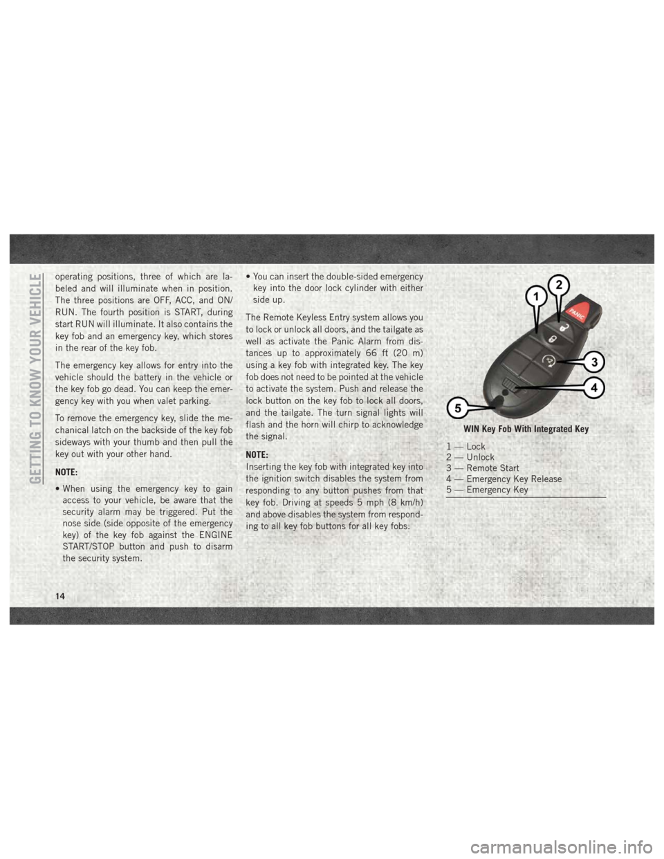
The emergency key allows for entry into the
vehicle should the battery in the vehicle or
the key fob go dead. You can keep the emer-
gency key with you when valet parking.
To remove the emergency key, slide the me-
chanical latch on the backside of the key fob
sideways with your thumb and then pull the
key out with your other hand.
NOTE:
• When using the emergency key to gainaccess to your vehicle, be aware that the
security alarm may be triggered. Put the
nose side (side opposite of the emergency
key) of the key fob against the ENGINE
START/STOP button and push to disarm
the security system. • You can insert the double-sided emergency
key into the door lock cylinder with either
side up.
The Remote Keyless Entry system allows you
to lock or unlock all doors, and the tailgate as
well as activate the Panic Alarm from dis-
tances up to approximately 66 ft (20 m)
using a key fob with integrated key. The key
fob does not need to be pointed at the vehicle
to activate the system. Push and release the
lock button on the key fob to lock all doors,
and the tailgate. The turn signal lights will
flash and the horn will chirp to acknowledge
the signal.
NOTE:
Inserting the key fob with integrated key into
the ignition switch disables the system from
responding to any button pushes from that
key fob. Driving at speeds 5 mph (8 km/h)
and above disables the system from respond-
ing to all key fob buttons for all key fobs.
WIN Key Fob With Integrated Key
1 — Lock
2 — Unlock
3 — Remote Start
4 — Emergency Key Release
5 — Emergency Key
GETTING TO KNOW YOUR VEHICLE
14
Page 18 of 298
NOTE:
Changes or modifications not expressly ap-
proved by the party responsible for compli-
ance could void the user’s authority to oper-
ate the equipment.
IGNITION SWITCH
Wireless Ignition Node (WIN) —
If Equipped
The Wireless Ignition Node (WIN) operates
similar to an ignition switch. It has four
operating positions, three with detents and
one that is spring-loaded. The detent posi-
tions are OFF, ACC, and ON/RUN. The START
position is a spring-loaded momentary con-
tact position. When released from the START
position, the switch automatically returns to
the ON/RUN position.
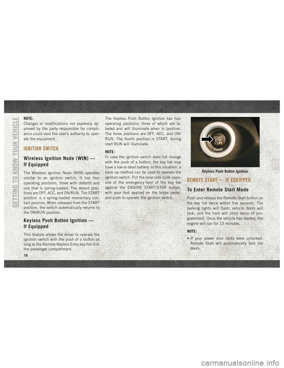
Keyless Push Button Ignition —
If Equipped
This feature allows the driver to operate the
ignition switch with the push of a button as
long as the Remote Keyless Entry key fob is in
the passenger compartment.The Keyless Push Button Ignition has four
operating positions; three of which are la-
beled and will illuminate when in position.
The three positions are OFF, ACC, and ON/
RUN. The fourth position is START, during
start RUN will illuminate.
NOTE:
In case the ignition switch does not change
with the push of a button, the key fob may
have a low or dead battery. In this situation, a
back up method can be used to operate the
ignition switch. Put the nose side (side oppo-
site of the emergency key) of the key fob
against the ENGINE START/STOP button,
with your foot applied on the brake pedal,
and push to operate the ignition switch.
REMOTE START — IF EQUIPPED
To Enter Remote Start Mode
Push and release the Remote Start button on
the key fob twice within five seconds. The
parking lights will flash, vehicle doors will
lock, and the horn will chirp twice (if pro-
grammed). Once the vehicle has started, the
engine will run for 15 minutes.
NOTE:
• If your power door locks were unlocked,
Remote Start will automatically lock the
doors.
Keyless Push Button Ignition
GETTING TO KNOW YOUR VEHICLE
16
Page 19 of 298
• If an engine fault is present or fuel level islow, the vehicle will start and then shut
down in 10 seconds.
• The park lamps will turn on and remain on during Remote Start mode.
• For security, power window and power sun- roof operation (if equipped) are disabled
when the vehicle is in the Remote Start
mode.
• The engine can be started two consecutive times (two 15-minute cycles) with the key
fob. However, the ignition must be placed
in the ON/RUN position before you can
repeat the start sequence for a third cycle.
To Exit Remote Start Mode
Without Driving The Vehicle
Push and release the remote start button one
time or allow the engine to run for the entire
15-minute cycle.
NOTE:
To avoid unintentional shutdowns, the system
will disable with a one time push of the
remote start button for two seconds after
receiving a valid remote start request.
To Exit Remote Start Mode And
Drive The Vehicle
Before the end of the 15-minute cycle, push
and release the unlock button on the key fob
to unlock the doors and disarm the vehicle
security alarm system (if equipped). Then,
prior to the end of the 15-minute cycle, cycle
the ignition to the ON/RUN position.
General Information
The following regulatory statement applies to
all radio frequency (RF) devices equipped in
this vehicle:
This device complies with Part 15 of the FCC
Rules and with Industry Canada license-
exempt RSS standard(s). Operation is sub-
ject to the following two conditions:
1. This device may not cause harmful inter-
ference, and
2. This device must accept any interference received, including interference that may
cause undesired operation. NOTE:
Changes or modifications not expressly ap-
proved by the party responsible for compli-
ance could void the user’s authority to oper-
ate the equipment.
VEHICLE SECURITY ALARM
The vehicle security alarm monitors the ve-
hicle doors and ignition for unauthorized op-
eration. When the vehicle security alarm is
activated, interior switches for door locks are
disabled. The system provides both audible
and visible signals for the first three minutes.
The horn will sound, the headlights will turn
on, the park lamps and/or turn signals will
flash and vehicle security light will flash
repeatedly. For an additional 15 minutes
only, the headlights will turn on, the park
lamps and/or turn signals, and vehicle secu-
rity light will flash.
17
Page 21 of 298
battery is reconnected; the exterior lights will
flash, and the horn will sound. If this occurs,
disarm the vehicle security alarm.
DOORS
Keyless Enter-N-Go — Passive
Entry
The Passive Entry system is an enhancement
to the vehicle’s Remote Keyless Entry system
and a feature of Keyless Enter-N-Go. This
feature allows you to lock and unlock the
vehicle’s door(s) without having to push the
key fob lock or unlock buttons.
NOTE:
•
Refer to “Uconnect Settings” in “Multimedia”
in the Owner’s Manual at
www.mopar.com/
en-us/care/owners-manual.html (U.S.
Residents) or www.owners.mopar.ca
(Canadian Residents) for further information.
• If wearing gloves on your hands, or if it has been raining/snowing on the Passive Entry
door handle, the unlock sensitivity can be
affected, resulting in a slower response
time. • If the vehicle is unlocked by Passive Entry
and no door is opened within 60 seconds,
the vehicle will re-lock and if equipped will
arm the security alarm.
• The vehicles security alarm can be armed/ disarmed by pushing the passive entry key
fob lock/unlock buttons (if equipped).
• The key fob may not be able to be detected by the vehicle passive entry system if it is
located next to a mobile phone, laptop or
other electronic device; these devices may
block the key fob's wireless signal and pre-
vent the passive entry handle from locking/
unlocking the vehicle.
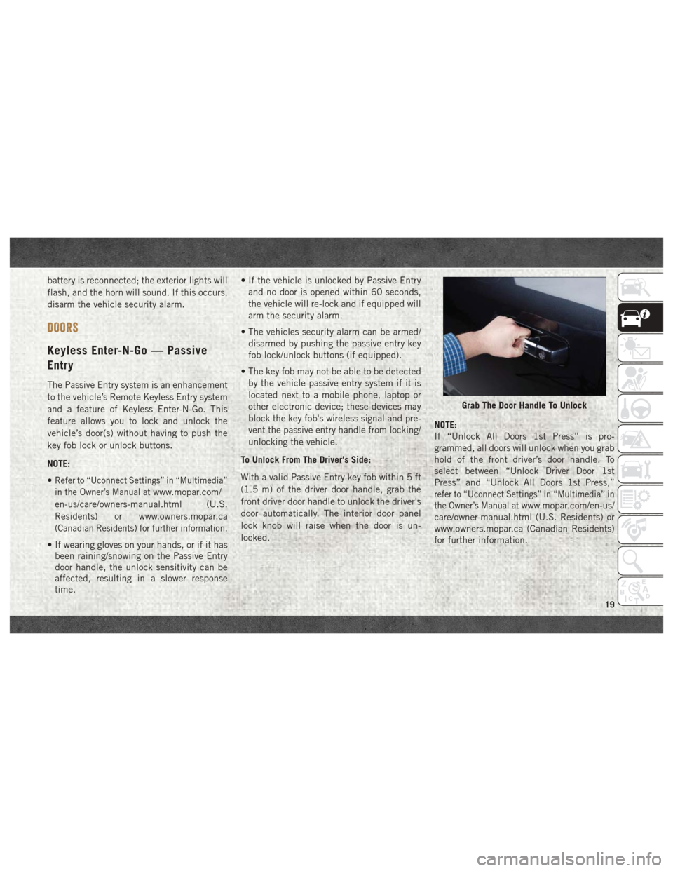
To Unlock From The Driver's Side:
With a valid Passive Entry key fob within 5 ft
(1.5 m) of the driver door handle, grab the
front driver door handle to unlock the driver's
door automatically. The interior door panel
lock knob will raise when the door is un-
locked. NOTE:
If “Unlock All Doors 1st Press” is pro-
grammed, all doors will unlock when you grab
hold of the front driver’s door handle. To
select between “Unlock Driver Door 1st
Press” and “Unlock All Doors 1st Press,”
refer to “Uconnect Settings” in “Multimedia” in
the Owner’s Manual at
www.mopar.com/en-us/
care/owner-manual.html (U.S. Residents) or
www.owners.mopar.ca (Canadian Residents)
for further information.
Grab The Door Handle To Unlock
19
Page 23 of 298
The vehicle doors can also be locked by using
the key fob lock button or the lock button
located on the vehicle’s interior door panel.
General Information
The following regulatory statement applies to
all radio frequency (RF) devices equipped in
this vehicle:
This device complies with Part 15 of the FCC
Rules and with Industry Canada license-
exempt RSS standard(s). Operation is sub-
ject to the following two conditions:
1. This device may not cause harmful inter-ference, and
2. This device must accept any interference received, including interference that may
cause undesired operation.
NOTE:
Changes or modifications not expressly ap-
proved by the party responsible for compli-
ance could void the user’s authority to oper-
ate the equipment.
SEATS
Seats are a part of the Occupant Restraint
System of the vehicle.
WARNING!
• It is dangerous to ride in a cargo area, inside or outside of a vehicle. In a colli-
sion, people riding in these areas are
more likely to be seriously injured or
killed.
• Do not allow people to ride in any area of
your vehicle that is not equipped with
seats and seat belts. In a collision,
people riding in these areas are more
likely to be seriously injured or killed.
• Be sure everyone in your vehicle is in a
seat and using a seat belt properly.
Driver Memory Seat — If Equipped
This feature allows the driver to store up to
two different memory profiles for easy recall
through a memory switch. Each memory pro-
file contains desired position settings for the
driver’s seat, side mirrors, adjustable pedals
(if equipped) and a set of desired radio sta- tion presets. Your remote keyless entry key
fob can also be programmed to recall the
same positions when the unlock button is
pushed.
NOTE:
Your vehicle is equipped with two key fobs,
one key fob can be linked to memory position
1 and the other key fob can be linked to
memory position 2.
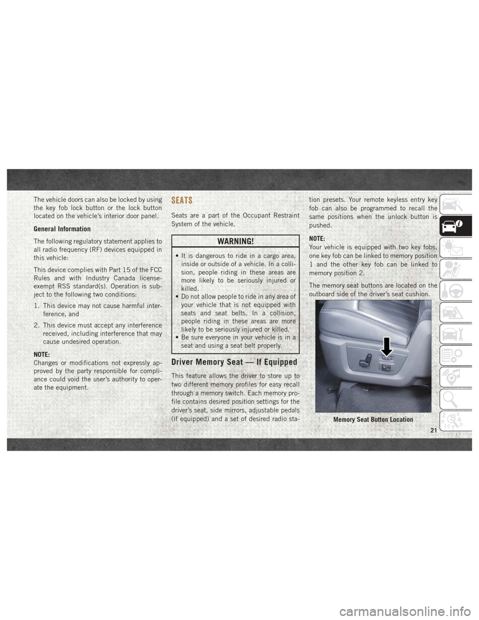
The memory seat buttons are located on the
outboard side of the driver’s seat cushion.
Memory Seat Button Location
21
Page 26 of 298
Each stored memory setting will have an
associated Easy Entry and Easy Exit position.
NOTE:
The Easy Entry/Exit feature is not enabled
when the vehicle is delivered from the fac-
tory. The Easy Entry/Exit feature is enabled
(or later disabled) through the programmable
features in the Uconnect system. Refer to
“Uconnect Settings” in “Multimedia” in the
Owner’s Manual at www.mopar.com/en-us/
care/owners-manual.html (U.S. Residents) or
www.owners.mopar.ca (Canadian Residents)
for further information.
Heated Seats
On some models, the front and rear seats may
be equipped with heaters located in the seat
cushions and seat backs.
WARNING!
• Persons who are unable to feel pain tothe skin because of advanced age,
chronic illness, diabetes, spinal cord in-
jury, medication, alcohol use, exhaus-
tion or other physical condition must
WARNING!
exercise care when using the seat
heater. It may cause burns even at low
temperatures, especially if used for long
periods of time.
• Do not place anything on the seat or
seatback that insulates against heat,
such as a blanket or cushion. This may
cause the seat heater to overheat. Sit-
ting in a seat that has been overheated
could cause serious burns due to the
increased surface temperature of the
seat.
Front Heated Seats
The front heated seats control buttons are
located within the climate or controls screen
of the touchscreen.
• Press the heated seat button
once to
turn the HI setting on.
• Press the heated seat button
a second
time to turn the LO setting on.
• Press the heated seat button
a third
time to turn the heating elements off. If the HI-level setting is selected, the system
will automatically switch to LO-level after
approximately 60 minutes of continuous op-
eration. At that time, the display will change
from HI to LO, indicating the change. The
LO-level setting will turn off automatically
after approximately 45 minutes.
NOTE:
The engine must be running for the heated
seats to operate.
Vehicles Equipped With Remote Start
On models that are equipped with remote
start, the heated seats can be programed to
come on during a remote start.
If your vehicle is equipped with a touchscreen,
this feature can be programmed through the
Uconnect system. Refer to “Uconnect Settings”
in “Multimedia” at
www.mopar.com/en-us/
care/owners-manual.html (U.S. Residents) or
www.owners.mopar.ca (Canadian Residents)
for further information.
GETTING TO KNOW YOUR VEHICLE
24
Page 31 of 298
The heated steering wheel control button is
located on the center instrument panel below
the climate controls. There are also buttons
located within the climate or controls screen
of the touchscreen.
• Press the heated steering wheel button
once to turn the heating element on.
• Press the heated steering wheel button
a second time to turn the heating element
off.
NOTE:
The engine must be running for the heated
steering wheel to operate.
Vehicles Equipped With Remote Start
On models that are equipped with remote
start, the heated steering wheel can be pro-
grammed to come on during a remote start.
This feature can be programmed through the
Uconnect system. Refer to “Uconnect Set-
tings” in “Multimedia” in the Owner’s
Manual at www.mopar.com/en-us/care/
owners-manual.html (U.S. Residents) or
www.owners.mopar.ca (Canadian Residents)
for further information.
WARNING!
• Persons who are unable to feel pain to the skin because of advanced age,
chronic illness, diabetes, spinal cord in-
jury, medication, alcohol use, exhaus-
tion, or other physical conditions must
exercise care when using the steering
wheel heater. It may cause burns even at
low temperatures, especially if used for
long periods.
• Do not place anything on the steering
wheel that insulates against heat, such
as a blanket or steering wheel covers of
any type and material. This may cause
the steering wheel heater to overheat.
DRIVER ADJUSTABLE PEDALS —
IF EQUIPPED
The adjustable pedals system is designed to
allow a greater range of driver comfort for
steering wheel tilt and seat position. This
feature allows the brake, accelerator, and clutch pedals (if equipped) to move toward or
away from the driver to provide improved
position with the steering wheel.
The adjustable pedal switch is located to the
left side of the steering column.
• The pedals can be adjusted with the igni-
tion OFF.
• The pedals cannotbe adjusted when the
vehicle is in REVERSE or when the Speed
Control System is on. The following mes-
sages will appear on vehicles equipped with
an instrument cluster display if the pedals
are attempted to be adjusted when the
system is locked out: “Adjustable Pedal
Disabled — Cruise Control Engaged” or
“Adjustable Pedal Disabled — Vehicle In
Reverse”.
NOTE:
• Always adjust the pedals to a position that allows full pedal travel.
• Further small adjustments may be neces- sary to find the best possible seat/pedal
position.
29