ECU Ram 4500 Chassis Cab 2018 User Guide
[x] Cancel search | Manufacturer: RAM, Model Year: 2018, Model line: 4500 Chassis Cab, Model: Ram 4500 Chassis Cab 2018Pages: 298, PDF Size: 5.88 MB
Page 11 of 298
GETTING TO KNOW YOUR VEHICLE
VEHICLE USER GUIDE — IF EQUIPPED .11
KEYS......................13
Key Fobs ....................13
IGNITION SWITCH ..............16
Wireless Ignition Node (WIN) —
If Equipped...................16
Keyless Push Button Ignition —
If Equipped ...................16
REMOTE START — IF EQUIPPED .....16
To Enter Remote Start Mode........16
To Exit Remote Start Mode Without
Driving The Vehicle .............17
To Exit Remote Start Mode And Drive
The Vehicle ...................17
General Information .............17
VEHICLE SECURITY ALARM ........17
To Arm The System..............18
To Disarm The System ............18
DOORS.....................19
Keyless Enter-N-Go — Passive Entry . . .19
SEATS .....................21
Driver Memory Seat — If Equipped ....21
Heated Seats ..................24
HEAD RESTRAINTS ..............26
Front Head Restraint Adjustment .....26
Rear Head Restraint Adjustment ......26
Front Head Restraint Removal .......27
Rear Head Restraint Removal ........27
STEERING WHEEL..............28
Tilt Steering Column .............28
Heated Steering Wheel — If Equipped . .28
DRIVER ADJUSTABLE PEDALS —
IF EQUIPPED .................29
MIRRORS ...................30
Power Folding Outside Mirrors For Standard
And Trailer Tow — If Equipped .......30
EXTERIOR LIGHTS..............31
Headlight Switch...............31
Headlights ...................32
Multifunction Lever .............32
High/Low Beam Switch ...........32Automatic High Beam Headlamp Control —
If Equipped
..................32
Automatic Headlights — If Equipped . .33
Parking Lights And Panel Lights ......34
Headlights On With Wipers (Available
With Automatic Headlights Only) ......34
Turn Signals ..................34
Lane Change Assist — If Equipped ....34
Cargo Light ..................34
WINDSHIELD WIPERS AND WASHERS .34
Windshield Wipers ..............34
Rain Sensing Wipers — If Equipped . . .35
CLIMATE CONTROLS .............37
Automatic Climate Controls With A
Touchscreen..................37
Climate Control Functions ..........42
Automatic Temperature Control (ATC) —
If Equipped ...................43
Operating Tips .................44
HOOD......................44
To Open The Hood ..............44
To Close The Hood ..............45
GETTING TO KNOW YOUR VEHICLE
9
Page 15 of 298
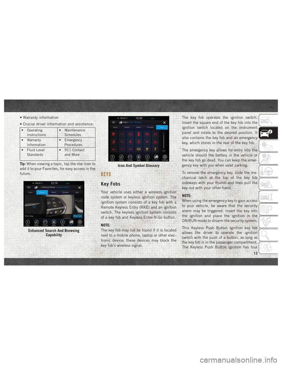
• Warranty information
• Crucial driver information and assistance:
• OperatingInstructions • Maintenance
Schedules
• Warranty Information • Emergency
Procedures
• Fluid Level Standards • 911 Contact
and More
Tip: When viewing a topic, tap the star icon to
add it to your Favorites, for easy access in the
future.
KEYS
Key Fobs
Your vehicle uses either a wireless ignition
node system or keyless ignition system. The
ignition system consists of a key fob with a
Remote Keyless Entry (RKE) and an ignition
switch. The keyless ignition system consists
of a key fob and Keyless Enter-N-Go button.
NOTE:
The key fob may not be found if it is located
next to a mobile phone, laptop or other elec-
tronic device; these devices may block the
key fob’s wireless signal. The key fob operates the ignition switch.
Insert the square end of the key fob into the
ignition switch located on the instrument
panel and rotate to the desired position. It
also contains the key fob and an emergency
key, which stores in the rear of the key fob.
The emergency key allows for entry into the
vehicle should the battery in the vehicle or
the key fob go dead. You can keep the emer-
gency key with you when valet parking.
To remove the emergency key, slide the me-
chanical latch at the top of the key fob
sideways with your thumb and then pull the
key out with your other hand.
NOTE:
When using the emergency key to gain access
to your vehicle, be aware that the security
alarm may be triggered. Insert the key into
the ignition and place the ignition in the
ON/RUN mode to disarm the security system.
This Keyless Push Button Ignition key fob
allows the driver to operate the ignition
switch with the push of a button, as long as
the key fob is in the passenger compartment.
The Keyless Push Button Ignition has four
Enhanced Search And Browsing
Capability
Icon And Symbol Glossary
13
Page 16 of 298
operating positions, three of which are la-
beled and will illuminate when in position.
The three positions are OFF, ACC, and ON/
RUN. The fourth position is START, during
start RUN will illuminate. It also contains the
key fob and an emergency key, which stores
in the rear of the key fob.
The emergency key allows for entry into the
vehicle should the battery in the vehicle or
the key fob go dead. You can keep the emer-
gency key with you when valet parking.
To remove the emergency key, slide the me-
chanical latch on the backside of the key fob
sideways with your thumb and then pull the
key out with your other hand.
NOTE:
• When using the emergency key to gainaccess to your vehicle, be aware that the
security alarm may be triggered. Put the
nose side (side opposite of the emergency
key) of the key fob against the ENGINE
START/STOP button and push to disarm
the security system. • You can insert the double-sided emergency
key into the door lock cylinder with either
side up.
The Remote Keyless Entry system allows you
to lock or unlock all doors, and the tailgate as
well as activate the Panic Alarm from dis-
tances up to approximately 66 ft (20 m)
using a key fob with integrated key. The key
fob does not need to be pointed at the vehicle
to activate the system. Push and release the
lock button on the key fob to lock all doors,
and the tailgate. The turn signal lights will
flash and the horn will chirp to acknowledge
the signal.
NOTE:
Inserting the key fob with integrated key into
the ignition switch disables the system from
responding to any button pushes from that
key fob. Driving at speeds 5 mph (8 km/h)
and above disables the system from respond-
ing to all key fob buttons for all key fobs.
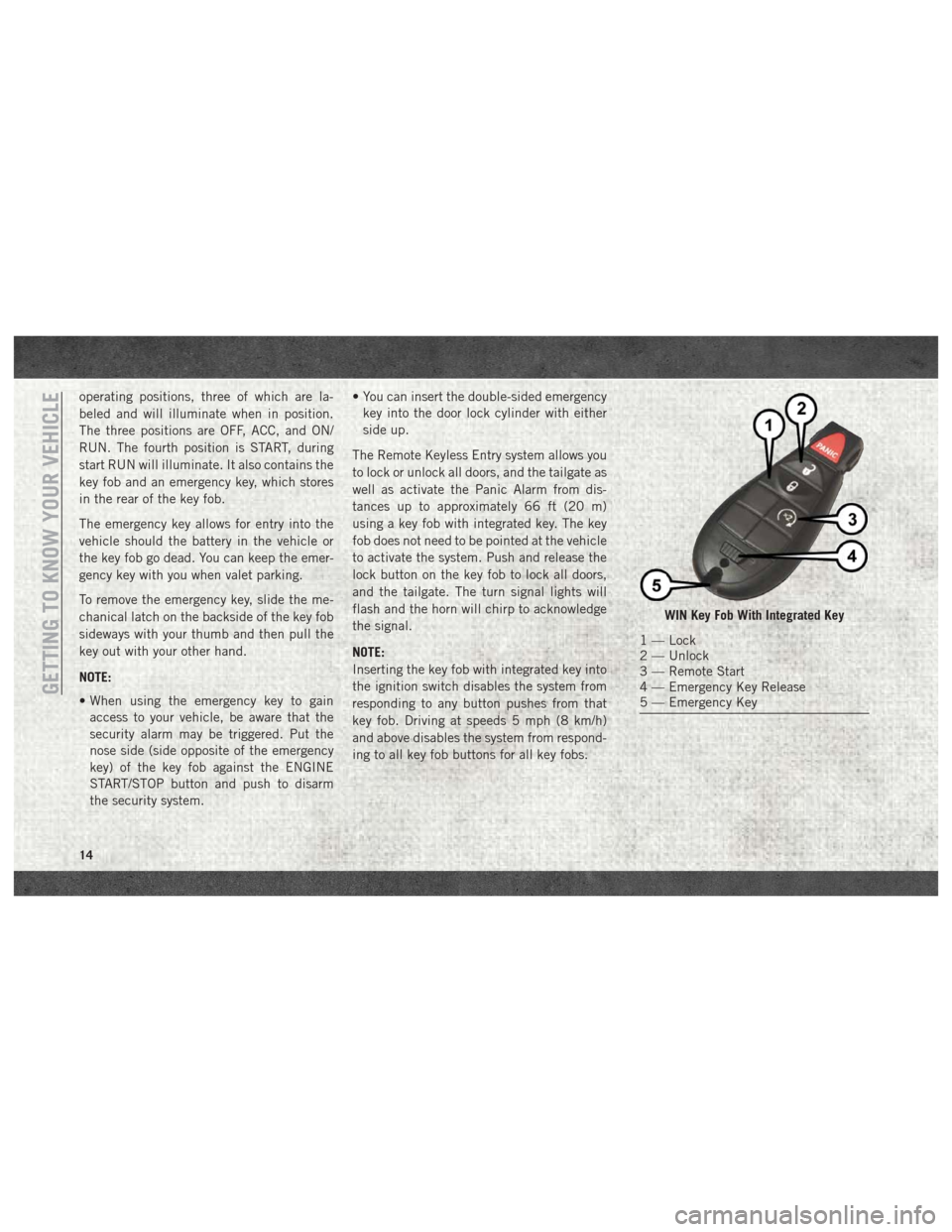
WIN Key Fob With Integrated Key
1 — Lock
2 — Unlock
3 — Remote Start
4 — Emergency Key Release
5 — Emergency Key
GETTING TO KNOW YOUR VEHICLE
14
Page 19 of 298
• If an engine fault is present or fuel level islow, the vehicle will start and then shut
down in 10 seconds.
• The park lamps will turn on and remain on during Remote Start mode.
• For security, power window and power sun- roof operation (if equipped) are disabled
when the vehicle is in the Remote Start
mode.
• The engine can be started two consecutive times (two 15-minute cycles) with the key
fob. However, the ignition must be placed
in the ON/RUN position before you can
repeat the start sequence for a third cycle.
To Exit Remote Start Mode
Without Driving The Vehicle
Push and release the remote start button one
time or allow the engine to run for the entire
15-minute cycle.
NOTE:
To avoid unintentional shutdowns, the system
will disable with a one time push of the
remote start button for two seconds after
receiving a valid remote start request.
To Exit Remote Start Mode And
Drive The Vehicle
Before the end of the 15-minute cycle, push
and release the unlock button on the key fob
to unlock the doors and disarm the vehicle
security alarm system (if equipped). Then,
prior to the end of the 15-minute cycle, cycle
the ignition to the ON/RUN position.
General Information
The following regulatory statement applies to
all radio frequency (RF) devices equipped in
this vehicle:
This device complies with Part 15 of the FCC
Rules and with Industry Canada license-
exempt RSS standard(s). Operation is sub-
ject to the following two conditions:
1. This device may not cause harmful inter-
ference, and
2. This device must accept any interference received, including interference that may
cause undesired operation. NOTE:
Changes or modifications not expressly ap-
proved by the party responsible for compli-
ance could void the user’s authority to oper-
ate the equipment.
VEHICLE SECURITY ALARM
The vehicle security alarm monitors the ve-
hicle doors and ignition for unauthorized op-
eration. When the vehicle security alarm is
activated, interior switches for door locks are
disabled. The system provides both audible
and visible signals for the first three minutes.
The horn will sound, the headlights will turn
on, the park lamps and/or turn signals will
flash and vehicle security light will flash
repeatedly. For an additional 15 minutes
only, the headlights will turn on, the park
lamps and/or turn signals, and vehicle secu-
rity light will flash.
17
Page 20 of 298
To Arm The System
Follow these steps to arm the vehicle security
alarm:
1. Remove the key from the ignition system(refer to "Starting The Engine" in "Starting
And Operating" for further information).
• For vehicles equipped with Keyless Enter-N-Go — Ignition, make sure the
vehicle ignition system is "OFF."
• For vehicles not equipped with Keyless Enter-N-Go — Ignition, make sure the
vehicle ignition system is "OFF" and
the key is physically removed from the
ignition.
2. Perform one of the following methods to lock the vehicle:
• Push lock button on the interior power door lock switch with the driver and/or
passenger door open.
• Push the lock button on the exterior Passive Entry Door Handle with a valid
key fob available in the same exterior zone (refer to "Keyless Enter- N-Go —
Passive Entry" in "Getting To Know Your
Vehicle" for further information).
• Push the lock button on the key fob.
3. If any doors are open, close them.
The vehicle security alarm will set when you
use the power door locks, or use the key fob to
lock the doors. After all the doors are locked
and closed, the vehicle security light, in the
instrument panel cluster, will flash rapidly for
about 16 seconds to indicate that the alarm
is being set. After the alarm is set, the vehicle
security light will flash at a slower rate to
indicate that the system is armed.
To Disarm The System
The vehicle security alarm can be disarmed
using any of the following methods:
1. Push the unlock button on the key fob.
2. Grasp the Passive Entry Unlock Door Handle with a valid key fob within 5 ft
(1.5 m) of the passive entry door handle.
If equipped, refer to "Keyless Enter-N-Go
— Passive Entry" in "Getting To Know Your
Vehicle" for further information. 3. Cycle the ignition out of the OFF position.
• For vehicles equipped with KeylessEnter-N-Go — Ignition, push the Key-
less Ignition START/STOP button (re-
quires at least one valid key fob in the
vehicle).
• For vehicles not equipped with Keyless Enter-N-Go, insert a valid key into the
ignition switch and turn the key to the
ON position.
The vehicle security alarm is designed to
protect your vehicle. However, you can create
conditions where the system will give you a
false alarm. If one of the previously described
arming sequences has occurred, the vehicle
security alarm will arm regardless of whether
you are in the vehicle or not. If you remain in
the vehicle and open a door, the alarm will
sound. If this occurs, disarm the vehicle
security alarm.
If the vehicle security alarm is armed and the
battery becomes disconnected, the vehicle
security alarm will remain armed when theGETTING TO KNOW YOUR VEHICLE
18
Page 21 of 298
battery is reconnected; the exterior lights will
flash, and the horn will sound. If this occurs,
disarm the vehicle security alarm.
DOORS
Keyless Enter-N-Go — Passive
Entry
The Passive Entry system is an enhancement
to the vehicle’s Remote Keyless Entry system
and a feature of Keyless Enter-N-Go. This
feature allows you to lock and unlock the
vehicle’s door(s) without having to push the
key fob lock or unlock buttons.
NOTE:
•
Refer to “Uconnect Settings” in “Multimedia”
in the Owner’s Manual at
www.mopar.com/
en-us/care/owners-manual.html (U.S.
Residents) or www.owners.mopar.ca
(Canadian Residents) for further information.
• If wearing gloves on your hands, or if it has been raining/snowing on the Passive Entry
door handle, the unlock sensitivity can be
affected, resulting in a slower response
time. • If the vehicle is unlocked by Passive Entry
and no door is opened within 60 seconds,
the vehicle will re-lock and if equipped will
arm the security alarm.
• The vehicles security alarm can be armed/ disarmed by pushing the passive entry key
fob lock/unlock buttons (if equipped).
• The key fob may not be able to be detected by the vehicle passive entry system if it is
located next to a mobile phone, laptop or
other electronic device; these devices may
block the key fob's wireless signal and pre-
vent the passive entry handle from locking/
unlocking the vehicle.
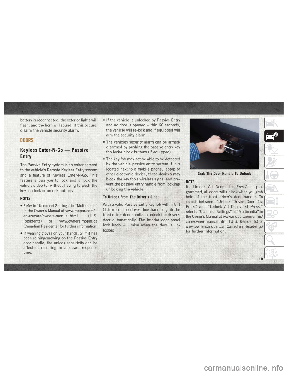
To Unlock From The Driver's Side:
With a valid Passive Entry key fob within 5 ft
(1.5 m) of the driver door handle, grab the
front driver door handle to unlock the driver's
door automatically. The interior door panel
lock knob will raise when the door is un-
locked. NOTE:
If “Unlock All Doors 1st Press” is pro-
grammed, all doors will unlock when you grab
hold of the front driver’s door handle. To
select between “Unlock Driver Door 1st
Press” and “Unlock All Doors 1st Press,”
refer to “Uconnect Settings” in “Multimedia” in
the Owner’s Manual at
www.mopar.com/en-us/
care/owner-manual.html (U.S. Residents) or
www.owners.mopar.ca (Canadian Residents)
for further information.
Grab The Door Handle To Unlock
19
Page 29 of 298
• Do not reposition the head restraint180 degrees to the incorrect position in an
attempt to gain additional clearance to the
back of the head.
Front Head Restraint Removal
To remove the head restraint, raise it up as far
as it can go. Then, push the adjustment
button and the release button at the base of
each post while pulling the head restraint up.
To reinstall the head restraint, put the head
restraint posts into the holes. Then, adjust it
to the appropriate height.
NOTE:
Do not reposition the head restraint 180 de-
grees to the incorrect position in an attempt
to gain additional clearance to the back of the
head.
WARNING!
• A loose head restraint thrown forward in
a collision or hard stop could cause se-
rious injury or death to occupants of the
vehicle. Always securely stow removed
head restraints in a location outside the
occupant compartment.
• ALL the head restraints MUST be rein-
stalled in the vehicle to properly protect
the occupants. Follow the re-installation
instructions above prior to operating the
vehicle or occupying a seat.
Rear Head Restraint Removal
To remove the head restraint, push the ad-
justment button and the release button while
pulling upward on the whole assembly. To
reinstall the head restraint, put the head
restraint posts into the holes and adjust it to
the appropriate height.
NOTE:
To remove outboard restraints, the rear seat
bottom must be folded up.
WARNING!
• A loose head restraint thrown forward ina collision or hard stop could cause se-
rious injury or death to occupants of the
vehicle. Always securely stow removed
head restraints in a location outside the
occupant compartment.
• ALL the head restraints MUST be rein-
stalled in the vehicle to properly protect
the occupants. Follow the re-installation
instructions above prior to operating the
vehicle or occupying a seat.
27
Page 47 of 298

1. Pull the hood release lever located belowthe steering wheel at the base of the
instrument panel.
2. Reach into the opening beneath the cen- ter of the hood and push the safety latch
lever to the left to release it, before raising
the hood.
To Close The Hood
Lower the hood to approximately 12 inches
(30 cm) from the engine compartment and
drop it. Make sure that the hood is completely
closed.
WARNING!
Be sure the hood is fully latched before
driving your vehicle. If the hood is not fully
latched, it could open when the vehicle is
in motion and block your vision. Failure to
follow this warning could result in serious
injury or death.
CAUTION!
To prevent possible damage, do not slam
the hood to close it. Use a firm downward
push at the front center of the hood to
ensure that both latches engage.
UNIVERSAL GARAGE DOOR OPENER
(HOMELINK)
• HomeLink replaces up to three hand-held
transmitters that operate devices such as
garage door openers, motorized gates,
lighting or home security systems. The
HomeLink unit is powered by your vehicles
12 Volt battery.
HomeLink Buttons
45
Page 55 of 298

GETTING TO KNOW YOUR INSTRUMENT PANEL
INSTRUMENT CLUSTER DISPLAY.....54
Instrument Cluster Display Controls ....54
Diesel Messages And Warnings —
6.7L Cummins Diesel Engine ........55
Oil Life Reset .................59
Instrument Cluster Display
Programmable Features ...........59
WARNING LIGHTS AND MESSAGES ....61
Red Warning Lights..............61
Yellow Warning Lights ............63
Yellow Indicator Lights ............67
Green Indicator Lights ............68
White Indicator Lights ............68
Blue Indicator Lights .............68
ONBOARD DIAGNOSTIC SYSTEM —
OBDII .....................69
Onboard Diagnostic System (OBD II)
Cybersecurity.................69
GETTING TO KNOW YOUR INSTRUMENT PANEL
53
Page 60 of 298
5 MPH (8 km/H) if the DEF system is not
serviced within less than 200 miles (322 km)
of the fault being detected.
When the DEF system needs to be serviced
the following warnings will display:
•Service DEF System See Dealer — This mes-
sage will display when the fault is initially
detected, each time the vehicle is started,
and periodically during driving. The mes-
sage will be accompanied by a single
chime. We recommend you drive to your
nearest authorized dealer and have your
vehicle serviced as soon as possible.
• 5 MPH Max Speed in 150 mi Service DEF
System See Dealer — This message will
display if the DEF system has not been
serviced after the “Service DEF System –
See Dealer” message is displayed. This
message will continuously display until the
mileage counter reaches zero, and will be
accompanied by a periodic chime. The
message will continue to countdown until it
reaches zero unless the vehicle is serviced.
We recommend you drive to your nearest
authorized dealer and have your vehicle
serviced immediately. NOTE:
Under some circumstances this mileage
counter may start with a value of less than
150 miles (241 km). For example, if recur-
ring faults are detected in a time interval of
less than 40 hours, the counter may restart
at the value where it stopped when a previ-
ous fault was temporarily remedied, or at a
minimum of 50 miles (80 km).
•
5 MPH Max Speed on Restart, Long Idle or
Refuel Service DEF See Dealer — This mes-
sage will continuously display when the
mileage counter reaches zero, and will be
accompanied by a periodic chime.
The vehicle will only be capable of a maxi-
mum speed of 5 MPH upon the first of the
following conditions to occur: – If the vehicle is shutoff and restarted.
– If the vehicle is idled for an extendedperiod of time, approximately one hour
or greater.
– If the system detects that the level of fuel in the tank has increased. •
5 MPH Max Speed Service DEF System See
Dealer — This message will continuously
display, and will be accompanied by a pe-
riodic chime. Although the vehicle can be
started and placed in gear, the vehicle will
only operate at a maximum speed of
5 MPH. Your vehicle will require towing,
see your authorized dealer for service.
NOTE:
When this message is displayed, the engine
can still be started. However, the vehicle
will only operate at a maximum speed of
5 MPH.
• Incorrect DEF Detected See Dealer — This
message will display when the fault is ini-
tially detected, each time the vehicle is
started, and periodically during driving.
The message will be accompanied by a
single chime. We recommend you drive to
your nearest authorized dealer and have
your vehicle serviced as soon as possible.
RAM Active Air System
Your vehicle is equipped with an advanced
Ram Active Air system that provides en-
hanced performance, especially when towingGETTING TO KNOW YOUR INSTRUMENT PANEL
58