change wheel Ram 4500 Chassis Cab 2018 User Guide
[x] Cancel search | Manufacturer: RAM, Model Year: 2018, Model line: 4500 Chassis Cab, Model: Ram 4500 Chassis Cab 2018Pages: 298, PDF Size: 5.88 MB
Page 3 of 298
Congratulations on selecting your new FCA
US LLC vehicle. Be assured that it represents
precision workmanship, distinctive styling,
and high quality.
ALWAYS drive safely and pay attention to the
road. ALWAYS drive safely with your hands on
the steering wheel. You have full responsibil-
ity and assume all risks related to the use of
the features and applications in this vehicle.
Only use the features and applications when
it is safe to do so. Failure to do so may result
in an accident involving serious injury or death.
This guide illustrates and describes the op-
eration of features and equipment that are
either standard or optional on this vehicle.
This guide may also include a description of
features and equipment that are no longer
available or were not ordered on this vehicle.
Please disregard any features and equipment
described in this guide that are not available
on this vehicle. FCA US LLC reserves the
right to make changes in design and specifi-
cations and/or make additions to or improve-
ments to its products without imposing any
obligation upon itself to install them on prod-
ucts previously manufactured.This User Guide has been prepared to help
you quickly become acquainted with the im-
portant features of your vehicle. It contains
most things you will need to operate and
maintain the vehicle, including emergency
information.
For complete owner information, refer to your
Owner’s Manual at www.mopar.com/en-us/care/
owners-manual.html (U.S. Residents) or
www.owners.mopar.ca (Canadian Residents)
for further information.
For your convenience,
the information contained on this site may
also be printed and saved for future refer-
ence.
FCA US LLC is committed to protecting our
environment and natural resources. By con-
verting from paper to electronic delivery for
the majority of the user information for your
vehicle, together we greatly reduce the de-
mand for tree-based products and lessen the
stress on our environment.
When it comes to service, remember that your
authorized dealer knows your vehicle best,
has factory-trained technicians and genuine
MOPAR
®parts, and cares about your satis-
faction.
WELCOME FROM FCA US LLC
1
Page 11 of 298
GETTING TO KNOW YOUR VEHICLE
VEHICLE USER GUIDE — IF EQUIPPED .11
KEYS......................13
Key Fobs ....................13
IGNITION SWITCH ..............16
Wireless Ignition Node (WIN) —
If Equipped...................16
Keyless Push Button Ignition —
If Equipped ...................16
REMOTE START — IF EQUIPPED .....16
To Enter Remote Start Mode........16
To Exit Remote Start Mode Without
Driving The Vehicle .............17
To Exit Remote Start Mode And Drive
The Vehicle ...................17
General Information .............17
VEHICLE SECURITY ALARM ........17
To Arm The System..............18
To Disarm The System ............18
DOORS.....................19
Keyless Enter-N-Go — Passive Entry . . .19
SEATS .....................21
Driver Memory Seat — If Equipped ....21
Heated Seats ..................24
HEAD RESTRAINTS ..............26
Front Head Restraint Adjustment .....26
Rear Head Restraint Adjustment ......26
Front Head Restraint Removal .......27
Rear Head Restraint Removal ........27
STEERING WHEEL..............28
Tilt Steering Column .............28
Heated Steering Wheel — If Equipped . .28
DRIVER ADJUSTABLE PEDALS —
IF EQUIPPED .................29
MIRRORS ...................30
Power Folding Outside Mirrors For Standard
And Trailer Tow — If Equipped .......30
EXTERIOR LIGHTS..............31
Headlight Switch...............31
Headlights ...................32
Multifunction Lever .............32
High/Low Beam Switch ...........32Automatic High Beam Headlamp Control —
If Equipped
..................32
Automatic Headlights — If Equipped . .33
Parking Lights And Panel Lights ......34
Headlights On With Wipers (Available
With Automatic Headlights Only) ......34
Turn Signals ..................34
Lane Change Assist — If Equipped ....34
Cargo Light ..................34
WINDSHIELD WIPERS AND WASHERS .34
Windshield Wipers ..............34
Rain Sensing Wipers — If Equipped . . .35
CLIMATE CONTROLS .............37
Automatic Climate Controls With A
Touchscreen..................37
Climate Control Functions ..........42
Automatic Temperature Control (ATC) —
If Equipped ...................43
Operating Tips .................44
HOOD......................44
To Open The Hood ..............44
To Close The Hood ..............45
GETTING TO KNOW YOUR VEHICLE
9
Page 61 of 298
under demanding hot or high altitude condi-
tions. If the instrument cluster display dis-
plays the message “Active Airbox Service
Required See Dealer”, vehicle performance
may be reduced until service is performed by
an authorized RAM dealer.
Oil Life Reset
Your vehicle is equipped with an engine oil
change indicator system. The “Oil Change
Required” message will display in the instru-
ment cluster display after a single chime has
sounded, to indicate the next scheduled oil
change interval. The engine oil change indi-
cator system is duty cycle based, which
means the engine oil change interval may
fluctuate, dependent upon your personal
driving style.
NOTE:
Use the steering wheel instrument cluster
display controls for the following proce-
dure(s).Vehicles Equipped With Passive Entry
1. Without pushing the brake pedal, push
the ENGINE START/STOP button and
place the ignition to the ON/RUN position
(do not start the engine).
2. Push and release the downarrow button to
scroll downward through the main menu
to “Vehicle Info.”
3. Push and release the rightarrow button to
access the ”Vehicle Info” screen, then
scroll up or down to select “Oil Life.”
4. Push and hold the rightarrow button to
select “Reset”.
5. Push and release the downarrow button to
select “Yes,” then push and release the
right arrow button to select reset of the Oil
Life to 100%.
6. Push and release the uparrow button to
exit the instrument cluster display screen. Vehicles Not Equipped With Passive Entry
1. Without pushing the brake pedal, cycle
the ignition to the ON/RUN position (do
not start the engine).
2. Push and release the downarrow button to
scroll downward through the main menu
to “Vehicle Info.”
3. Push and release the rightarrow button to
access the “Vehicle Info” screen then
scroll up or down to select “Oil Life.”
4. Push and hold the rightarrow button to
select “YES” by pushing the rightarrow
then push and release the rightarrow
button to select reset of the Oil Life to
100%.
5. Push and release the uparrow button to
exit the instrument cluster display screen.
NOTE:
If the indicator message illuminates when
you start the vehicle, the Oil Life indicator
system did not reset. If necessary, repeat this
procedure.
59
Page 62 of 298
Instrument Cluster Display Programmable Features
The instrument cluster display can be used to view or change the following settings. Push theupordown arrow button until System Setup
displays, then push the rightarrow button. Scroll through the settings using the upordown arrow button. Push the rightarrow button to change
the setting. Push the leftarrow button to scroll back to a previous menu or sub menu.
• Language Select • Remote Start Comfort System
• Units • Easy Exit Seat
• ParkSense • Key Off Power Delay
• Tilt Mirror In Reverse • Commercial Settings
• Rain Sensing Wipers • Air Suspension Display Alerts
• Hill Start Assist • Aero Ride Height Mode
• Headlights Off Delay • Tire/Jack Mode
• Illuminated Approach • Transport Mode
• Headlights On With Wipers • Wheel Alignment Mode
• Automatic Highbeams • Horn With Remote Lower
• Flash Lights With Lock • Lights With Remote Lower
• Auto Lock Doors • Trailer Select
• Auto Unlock Doors • Brake Type
• Sound Horn With Remote Start • Trailer Name
• Sound Horn With Remote Lock • Compass Variance
• Remote Unlock Sequence • Calibrate Compass
• Key Fob Linked To Memory • Fuel Saver Display
• Passive Entry • Park Assist Front Chime Volume
• Park Assist Rear Chime Volume
GETTING TO KNOW YOUR INSTRUMENT PANEL
60
Page 75 of 298

CAUTION!
• The TPMS has been optimized for theoriginal equipment tires and wheels.
TPMS pressures and warning have been
established for the tire size equipped on
your vehicle. Undesirable system opera-
tion or sensor damage may result when
using replacement equipment that is not
of the same size, type, and/or style.
Aftermarket wheels can cause sensor
damage.
• Using aftermarket tire sealants may
cause the Tire Pressure Monitoring Sys-
tem (TPMS) sensor to become inoper-
able. After using an aftermarket tire
sealant it is recommended that you take
your vehicle to an authorized dealership
to have your sensor function checked.
• After inspecting or adjusting the tire
pressure always reinstall the valve stem
cap. This will prevent moisture and dirt
from entering the valve stem, which
could damage the TPMS sensor. NOTE:
• The TPMS is not intended to replace nor-
mal tire care and maintenance or to provide
warning of a tire failure or condition.
• The TPMS should not be used as a tire pressure gauge while adjusting your tire
pressure.
• Driving on a significantly under-inflated tire causes the tire to overheat and can lead to
tire failure. Under-inflation also reduces
fuel efficiency and tire tread life, and may
affect the vehicle’s handling and stopping
ability.
• The TPMS is not a substitute for proper tire maintenance, and it is the driver’s respon-
sibility to maintain correct tire pressure
using an accurate tire pressure gauge, even
if under-inflation has not reached the level
to trigger illumination of the TPM Telltale
Light.
• Seasonal temperature changes will affect tire pressure, and the TPMS will monitor
the actual tire pressure in the tire.
Premium System
The Tire Pressure Monitor System (TPMS)
uses wireless technology with wheel rim
mounted electronic sensors to monitor tire
pressure levels. Sensors, mounted to each
wheel as part of the valve stem, transmit tire
pressure readings to the receiver module.
NOTE:
It is particularly important for you to check
the tire pressure in all of the tires on your
vehicle monthly and to maintain the proper
pressure.
The TPMS consists of the following compo-
nents:
• Receiver module
• Four tire pressure monitoring sensors
• Various tire pressure monitoring systemmessages, which display in the instrument
cluster
• Tire pressure monitoring telltale light
Tire Pressure Monitoring Low Pressure Warnings
73
Page 78 of 298

Tire Pressure Information System (TPIS)
Chassis Cab — If Equipped
Your vehicle may be equipped with a Tire
Pressure Information System (TPIS).
The Tire Pressure Information System (TPIS)
uses wireless technology with wheel rim
mounted electronic sensors to transmit tire
pressure levels. Sensors mounted to each
wheel as part of the valve stem transmit tire
pressure readings to the receiver module.
NOTE:
It is particularly important for you to check
the tire pressure in all of the tires on your
vehicle monthly and to maintain the proper
pressure.
The TPIS consists of the following compo-
nents:
• Receiver module
• Four TPM sensors (Single Rear Wheel[SRW] applications)
• Six TPM sensors (Dual Rear Wheel [DRW] applications)
• Pressure display in the instrument cluster display. The TPIS system will display all four (Single
Rear Wheel [SRW] applications) or six (Dual
Rear Wheel [DRW] applications) tire pressure
values in the instrument cluster display.
If a system fault is detected, the instrument
cluster will display a "SERVICE TPM SYS-
TEM" message for a minimum of five seconds
and then display dashes (- -) in place of the
pressure value to indicate which sensor is not
being received.
If the ignition switch is cycled, this sequence
will repeat, providing the system fault still
exists. If the system fault no longer exists, the
"SERVICE TPM SYSTEM" message will no
longer be displayed, and a pressure value will
display in place of the dashes. A system fault
can occur due to any of the following:
• Signal interference due to electronic de-
vices or driving next to facilities emitting
the same radio frequencies as the TPM
sensors.
• Installing aftermarket window tinting that contains materials that may block radio
wave signals.
• Accumulation of snow or ice around the wheels or wheel housings. • Using tire chains on the vehicle.
• Using wheels/tires not equipped with TPM
sensors.
General Information
This device complies with Part 15 of the FCC
rules and RSS 210 of Industry Canada. Op-
eration is subject to the following conditions:
1. This device may not cause harmful
interference.
2. This device must accept any interference received, including interference that may
cause undesired operation.
NOTE:
Changes or modifications not expressly ap-
proved by the party responsible for compli-
ance could void the user’s authority to oper-
ate the equipment.
OCCUPANT RESTRAINT SYSTEMS
Some of the most important safety features in
your vehicle are the restraint systems:
SAFETY
76
Page 97 of 298
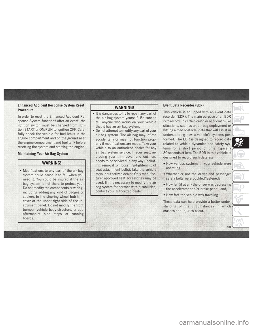
Enhanced Accident Response System Reset
Procedure
In order to reset the Enhanced Accident Re-
sponse System functions after an event, the
ignition switch must be changed from igni-
tion START or ON/RUN to ignition OFF. Care-
fully check the vehicle for fuel leaks in the
engine compartment and on the ground near
the engine compartment and fuel tank before
resetting the system and starting the engine.
Maintaining Your Air Bag System
WARNING!
• Modifications to any part of the air bagsystem could cause it to fail when you
need it. You could be injured if the air
bag system is not there to protect you.
Do not modify the components or wiring,
including adding any kind of badges or
stickers to the steering wheel hub trim
cover or the upper right side of the in-
strument panel. Do not modify the front
bumper, vehicle body structure, or add
aftermarket side steps or running
boards.
WARNING!
• It is dangerous to try to repair any part ofthe air bag system yourself. Be sure to
tell anyone who works on your vehicle
that it has an air bag system.
• Do not attempt to modify any part of your
air bag system. The air bag may inflate
accidentally or may not function prop-
erly if modifications are made. Take your
vehicle to an authorized dealer for any
air bag system service. If your seat, in-
cluding your trim cover and cushion,
needs to be serviced in any way (includ-
ing removal or loosening/tightening of
seat attachment bolts), take the vehicle
to your authorized dealer. Only manufac-
turer approved seat accessories may be
used. If it is necessary to modify the air
bag system for persons with disabilities,
contact your authorized dealer.
Event Data Recorder (EDR)
This vehicle is equipped with an event data
recorder (EDR). The main purpose of an EDR
is to record, in certain crash or near crash-like
situations, such as an air bag deployment or
hitting a road obstacle, data that will assist in
understanding how a vehicle’s systems per-
formed. The EDR is designed to record data
related to vehicle dynamics and safety sys-
tems for a short period of time, typically
30 seconds or less. The EDR in this vehicle is
designed to record such data as:
• How various systems in your vehicle were
operating;
• Whether or not the driver and passenger safety belts were buckled/fastened;
• How far (if at all) the driver was depressing the accelerator and/or brake pedal; and,
• How fast the vehicle was traveling.
These data can help provide a better under-
standing of the circumstances in which
crashes and injuries occur.
95
Page 119 of 298
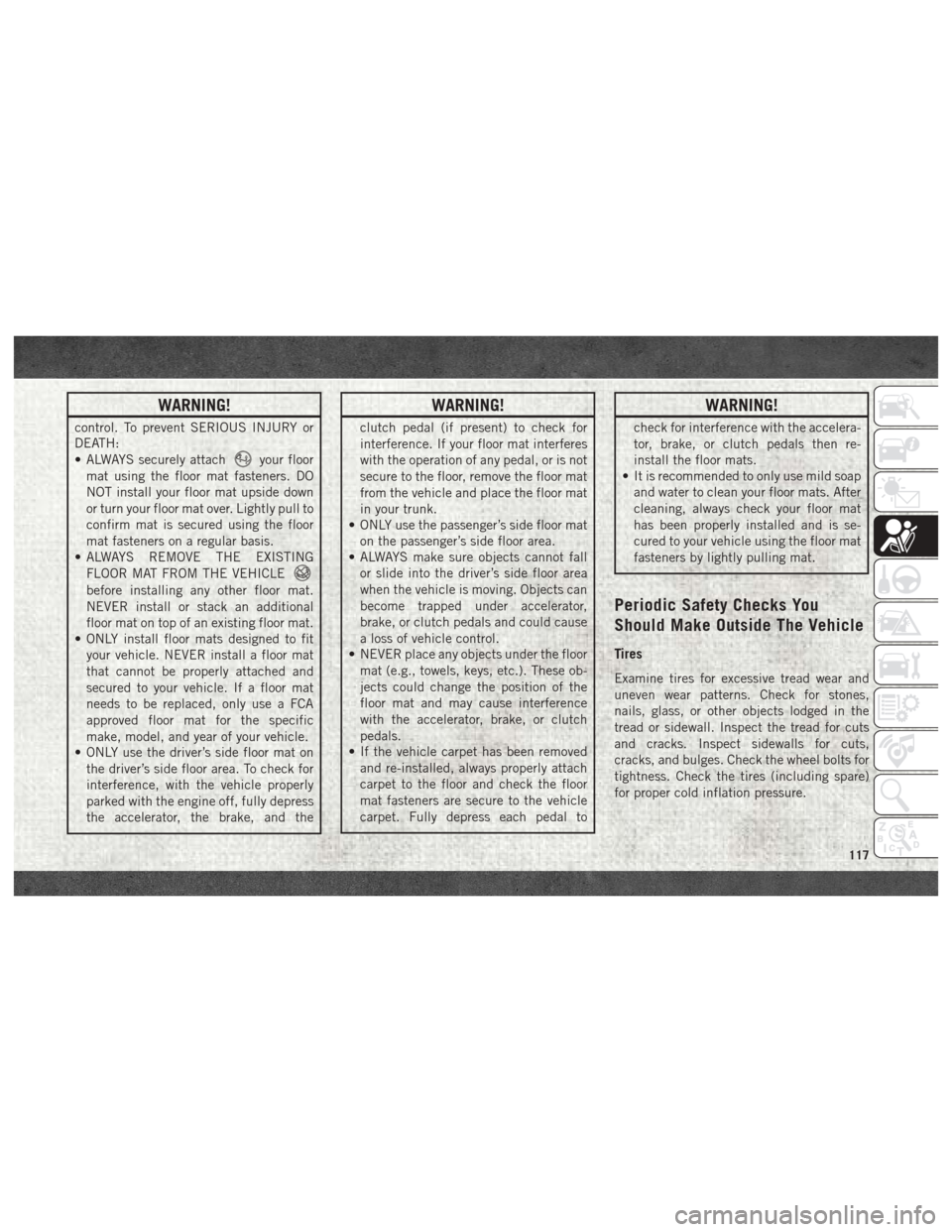
WARNING!
control. To prevent SERIOUS INJURY or
DEATH:
• ALWAYS securely attach
your floor
mat using the floor mat fasteners. DO
NOT install your floor mat upside down
or turn your floor mat over. Lightly pull to
confirm mat is secured using the floor
mat fasteners on a regular basis.
• ALWAYS REMOVE THE EXISTING
FLOOR MAT FROM THE VEHICLE
before installing any other floor mat.
NEVER install or stack an additional
floor mat on top of an existing floor mat.
• ONLY install floor mats designed to fit
your vehicle. NEVER install a floor mat
that cannot be properly attached and
secured to your vehicle. If a floor mat
needs to be replaced, only use a FCA
approved floor mat for the specific
make, model, and year of your vehicle.
• ONLY use the driver’s side floor mat on
the driver’s side floor area. To check for
interference, with the vehicle properly
parked with the engine off, fully depress
the accelerator, the brake, and the
WARNING!
clutch pedal (if present) to check for
interference. If your floor mat interferes
with the operation of any pedal, or is not
secure to the floor, remove the floor mat
from the vehicle and place the floor mat
in your trunk.
• ONLY use the passenger’s side floor mat
on the passenger’s side floor area.
• ALWAYS make sure objects cannot fall
or slide into the driver’s side floor area
when the vehicle is moving. Objects can
become trapped under accelerator,
brake, or clutch pedals and could cause
a loss of vehicle control.
• NEVER place any objects under the floor
mat (e.g., towels, keys, etc.). These ob-
jects could change the position of the
floor mat and may cause interference
with the accelerator, brake, or clutch
pedals.
• If the vehicle carpet has been removed
and re-installed, always properly attach
carpet to the floor and check the floor
mat fasteners are secure to the vehicle
carpet. Fully depress each pedal to
WARNING!
check for interference with the accelera-
tor, brake, or clutch pedals then re-
install the floor mats.
• It is recommended to only use mild soap
and water to clean your floor mats. After
cleaning, always check your floor mat
has been properly installed and is se-
cured to your vehicle using the floor mat
fasteners by lightly pulling mat.
Periodic Safety Checks You
Should Make Outside The Vehicle
Tires
Examine tires for excessive tread wear and
uneven wear patterns. Check for stones,
nails, glass, or other objects lodged in the
tread or sidewall. Inspect the tread for cuts
and cracks. Inspect sidewalls for cuts,
cracks, and bulges. Check the wheel bolts for
tightness. Check the tires (including spare)
for proper cold inflation pressure.
117
Page 133 of 298

If the transmission cannot be reset, autho-
rized dealer service is required.
Electronic Range Select (ERS) Operation
The Electronic Range Select (ERS) shift con-
trol allows the driver to limit the highest
available gear when the transmission is in
DRIVE. For example, if you set the transmis-
sion gear limit to 4 (fourth gear), the trans-
mission will not shift above fourth gear, but
will shift through the lower gears normally.
You can switch between DRIVE and ERS
mode at any vehicle speed. When the gear
selector is in the DRIVE position, the trans-
mission will operate automatically, shifting
between all available gears. Tapping the ERS
(-) switch will activate ERS mode, display the
current gear in the instrument cluster, and
set that gear as the top available gear. Once
in ERS mode, tapping (-) or (+) will change
the top available gear.To exit ERS mode, simply push and hold the
ERS (+) switch until the gear limit display
disappears from the instrument cluster.
WARNING!
Do not downshift for additional engine
braking on a slippery surface. The drive
wheels could lose their grip and the ve-
hicle could skid, causing a collision or
personal injury.
NOTE:
To select the proper gear position for maxi-
mum deceleration (engine braking), simply
push and hold the ERS (-) switch. The trans-
mission will shift to the range from which the
vehicle can best be slowed down.
CAUTION!
When using ERS for engine braking while
descending steep grades, be careful not to
overspeed the engine. Apply the brakes as
needed to prevent engine overspeed.
FOUR-WHEEL DRIVE OPERATION —
IF EQUIPPED
• Four-wheel drive trucks are equipped with either a manually shifted transfer case or an
electronically shifted transfer case. Refer to
the operating instructions for electronic
transfer case, located in this section for
further information.
• For further information on the manually shifted transfer case, refer to “Four Wheel
Drive Operation” in “Starting And Operat-
ing” in your Owner’s Manual located at
www.mopar.com/en-us/care/owners-manual.html
(U.S. Residents) or www.owners.mopar.ca
(Canadian Residents).
Column Gear Selector
131
Page 139 of 298

the forward vehicle speed exceeds 8 mph
(13 km/h), the transmission is shifted into
PARK or the ignition is switched to the OFF
position.
Whenever the Rear View Camera image is
activated through the "Backup Camera" but-
ton in the "Controls" menu, a display timer for
the image is initiated. The image will con-
tinue to be displayed until the display timer
exceeds 10 seconds and the vehicle speed is
above 8 mph (13 km/h) or the touchscreen
button "X" to disable display of the Rear View
Camera image is pressed.
NOTE:
If the vehicle speed remains below 8 mph
(13 km/h), the Rear View Camera image will
be displayed continuously until deactivated
via the touchscreen button "X".
If equipped with a Cargo Camera, a touch-
screen button
to indicate the current
active Camera image being displayed is made
available whenever the Rear View Camera
image is displayed. If equipped with a Cargo Camera, a touch-
screen button
to switch the display to
Cargo Camera image is made available when-
ever the Rear View Camera image is dis-
played.
A touchscreen button "X" to disable display of
the camera image is made available when the
vehicle is not in REVERSE gear.
When enabled, active guide lines are overlaid
on the image to illustrate the width of the
vehicle and its projected backup path based
on the steering wheel position. The active
guide lines will show separate zones that will
help indicate the distance to the rear of the
vehicle.
NOTE:
For further information about how to access
and change the programmable features of the
ParkView Rear Backup Camera, refer to
“Uconnect Settings ” in “Multimedia” in the
Owner’s Manual at www.mopar.com/en-us/
care/owners-manual.html (U.S. Residents) or
www.owners.mopar.ca (Canadian Residents)
for further information.WARNING!
Drivers must be careful when backing up
even when using the ParkView Rear Back
Up Camera. Always check carefully behind
your vehicle, and be sure to check for
pedestrians, animals, other vehicles, ob-
structions, or blind spots before backing
up. You are responsible for the safety of
your surroundings and must continue to
pay attention while backing up. Failure to
do so can result in serious injury or death.
CAUTION!
• To avoid vehicle damage, ParkView should only be used as a parking aid.
The ParkView camera is unable to view
every obstacle or object in your drive
path.
• To avoid vehicle damage, the vehicle
must be driven slowly when using
ParkView to be able to stop in time when
an obstacle is seen. It is recommended
that the driver look frequently over his/
her shoulder when using ParkView.
137