cruise control Ram 4500 Chassis Cab 2018 User Guide
[x] Cancel search | Manufacturer: RAM, Model Year: 2018, Model line: 4500 Chassis Cab, Model: Ram 4500 Chassis Cab 2018Pages: 298, PDF Size: 5.88 MB
Page 31 of 298
The heated steering wheel control button is
located on the center instrument panel below
the climate controls. There are also buttons
located within the climate or controls screen
of the touchscreen.
• Press the heated steering wheel button
once to turn the heating element on.
• Press the heated steering wheel button
a second time to turn the heating element
off.
NOTE:
The engine must be running for the heated
steering wheel to operate.
Vehicles Equipped With Remote Start
On models that are equipped with remote
start, the heated steering wheel can be pro-
grammed to come on during a remote start.
This feature can be programmed through the
Uconnect system. Refer to “Uconnect Set-
tings” in “Multimedia” in the Owner’s
Manual at www.mopar.com/en-us/care/
owners-manual.html (U.S. Residents) or
www.owners.mopar.ca (Canadian Residents)
for further information.
WARNING!
• Persons who are unable to feel pain to the skin because of advanced age,
chronic illness, diabetes, spinal cord in-
jury, medication, alcohol use, exhaus-
tion, or other physical conditions must
exercise care when using the steering
wheel heater. It may cause burns even at
low temperatures, especially if used for
long periods.
• Do not place anything on the steering
wheel that insulates against heat, such
as a blanket or steering wheel covers of
any type and material. This may cause
the steering wheel heater to overheat.
DRIVER ADJUSTABLE PEDALS —
IF EQUIPPED
The adjustable pedals system is designed to
allow a greater range of driver comfort for
steering wheel tilt and seat position. This
feature allows the brake, accelerator, and clutch pedals (if equipped) to move toward or
away from the driver to provide improved
position with the steering wheel.
The adjustable pedal switch is located to the
left side of the steering column.
• The pedals can be adjusted with the igni-
tion OFF.
• The pedals cannotbe adjusted when the
vehicle is in REVERSE or when the Speed
Control System is on. The following mes-
sages will appear on vehicles equipped with
an instrument cluster display if the pedals
are attempted to be adjusted when the
system is locked out: “Adjustable Pedal
Disabled — Cruise Control Engaged” or
“Adjustable Pedal Disabled — Vehicle In
Reverse”.
NOTE:
• Always adjust the pedals to a position that allows full pedal travel.
• Further small adjustments may be neces- sary to find the best possible seat/pedal
position.
29
Page 70 of 298
age. Refer to the “Draining Fuel/Water Sepa-
rator Filter” section in “Dealer Service” in
“Servicing And Maintenance” for further in-
formation.
— Low Diesel Exhaust Fluid (DEF)
Indicator Light — If Equipped
The Low Diesel Exhaust Fluid (DEF) Indicator
will illuminate if the vehicle is low on Diesel
Exhaust Fluid (DEF). Refer to “Starting And
Operating” for further information.
Green Indicator Lights
— Park/Headlight On Indicator Light
This indicator will illuminate when the park
lights or headlights are turned on.
— Front Fog Indicator Light —
If Equipped
This indicator will illuminate when the front
fog lights are on.
— Turn Signal Indicator Lights
When the left or right turn signal is activated,
the turn signal indicator will flash indepen-
dently and the corresponding exterior turn
signal lamps will flash. Turn signals can be
activated when the multifunction lever is
moved down (left) or up (right).
NOTE:
• A continuous chime will sound if the ve- hicle is driven more than 1 mile (1.6 km)
with either turn signal on.
• Check for an inoperative outside light bulb if either indicator flashes at a rapid rate.
— Cruise Control SET Indicator Light
This light will turn on when the speed control
is set to the desired speed. Refer to “Speed
Control” in “Starting And Operating” for fur-
ther information.
White Indicator Lights
— Cruise Control ON Indicator
This light will turn on when the speed control
is on, but not set.
— Speed Control SET Indicator Light
This light will turn on when the speed control
is set. Refer to “Speed Control — If
Equipped” in “Starting And Operating” for
further information.
Blue Indicator Lights
— High Beam Indicator Light
This indicator shows that the high beam
headlights are on. With the low beams acti-
vated, push the multifunction lever forward
(toward the front of the vehicle) to turn on the
high beams. Pull the multifunction lever rear-
ward (toward the rear of the vehicle) to turn
off the high beams. If the high beams are off,
pull the lever toward you for a temporary high
beam on, "flash to pass" scenario.
GETTING TO KNOW YOUR INSTRUMENT PANEL
68
Page 136 of 298

NOTE:
In order to ensure proper operation, the
Speed Control System has been designed to
shut down if multiple speed control functions
are operated at the same time. If this occurs,
the Speed Control System can be reactivated
by pushing the Speed Control ON/OFF button
and resetting the desired vehicle set speed.
To Activate
Push the ON/OFF button. The Cruise Indica-
tor Light in the instrument cluster display will
illuminate. To turn the system off, push the
ON/OFF button a second time. The Cruise
Indicator Light will turn off. The system
should be turned off when not in use.
WARNING!
Leaving the Speed Control system on when
not in use is dangerous. You could acci-
dentally set the system or cause it to go
faster than you want. You could lose con-
trol and have an accident. Always leave the
system off when you are not using it.
To Set A Desired Speed
Turn the Speed Control on. When the vehicle
has reached the desired speed, push the SET
(-) button and release. Release the accelera-
tor and the vehicle will operate at the se-
lected speed.
NOTE:
The vehicle should be traveling at a steady
speed and on level ground before pushing the
SET (-) button.
To Vary The Speed Setting
To Increase Speed
When the Speed Control is set, you can in-
crease speed by pushing the RES (+) button.
The driver’s preferred units can be selected
through the instrument panel settings if
equipped. Refer to “Getting To Know Your
Instrument Panel” in the Owner’s Manual at
www.mopar.com/en-us/care/owners-manual.html
(U.S. Residents) or www.owners.mopar.ca
(Canadian Residents) for more information.
The speed decrement shown is dependant on
the chosen speed unit of U.S. (mph) or Met-
ric (km/h):U.S. Speed (mph)
• Pushing the RES (+) button once will result
in a 1 mph increase in set speed. Each
subsequent tap of the button results in an
increase of 1 mph.
• If the button is continually pushed, the set speed will continue to increase until the
button is released, then the new set speed
will be established.
Metric Speed (km/h)
• Pushing the RES (+) button once will result in a 1 km/h increase in set speed. Each
subsequent tap of the button results in an
increase of 1 km/h.
• If the button is continually pushed, the set speed will continue to increase until the
button is released, then the new set speed
will be established.
To Decrease Speed
When the Speed Control is set, you can de-
crease speed by pushing the SET (-) button.
The driver’s preferred units can be selected
through the instrument panel settings if
equipped. Refer to “Getting To Know YourSTARTING AND OPERATING
134
Page 161 of 298

CavityCartridge Fuse Micro Fuse Description
F78 –10 Amp Red Engine Control Module / Electric Power Steering
F79 –15 Amp Blue Clearance Lights
F80 –10 Amp Red Universal Garage Door Opener / Compass
F81 –20 Amp Yellow Trailer Tow Right Turn / Stop Lights
F82 –10 Amp Red Steering Column Control Module / Cruise Control
F84 –15 Amp Blue Switch Bank / Instrument Cluster
F85 –10 Amp Red Airbag Module
F86 –10 Amp Red Airbag Module
F87 –10 Amp Red Air Suspension – If Equipped / Trailer Tow / Steering Col-
umn Control Module
F88 –15 Amp Blue Instrument Panel Cluster
F90/F91 –20 Amp Yellow Power Outlet (Rear Seats) Customer Selectable
F93 –20 Amp Yellow Cigar Lighter
F94 –10 Amp Red Shifter / Transfer Case Module
F95 –10 Amp Red Rear Camera / Park Assist
F96 –10 Amp Red Rear Seat Heater Switch
F97 –25 Amp Clear Rear Heated Seats & Heated Steering Wheel – If
Equipped
F98 –25 Amp Clear Front Heated Seats – If Equipped
F99 –10 Amp Red Climate Control
F100 –10 Amp Red Upfitters – If Equipped
F101 –15 Amp Blue Electrochromatic Mirror / Smart High Beams – If
Equipped
F104 –20 Amp Yellow Power Outlets (Instrument Panel / Center Console)
159
Page 292 of 298
Lower Anchors And Tethers
For Children...............101
Older Children And Child
Restraints .................98
Seating Positions ............100
Cleaning Wheels ..................206
Climate Control ................37
Manual ...................37
Clock .....................231
Clock Setting .................231
Compact Spare Tire .............204
Contract, Service ..............285
Cooling System Coolant Capacity ............213
Selection Of Coolant
(Antifreeze) ............214, 216
Cruise Light ..................68
Customer Assistance ............284
Customer Programmable Features . . . .256
Dealer Service ................186
Defroster, Windshield ............116
Delay (Intermittent) Wipers .........35
Diagnostic System, Onboard ........69
Diesel Fuel System, Re-Priming .....190
Disabled Vehicle Towing ..........169Disturb
....................270
Door Ajar ....................62
Door Ajar Light ................62
Draining Fuel/Water Separator Filter . . .187
Driver's Seat Back Tilt ............21
Dual Rear Wheels ..........210, 211
Electrical Power Outlets ...........49
Electronically Shifted Transfer Case . . .132
Electronic Range Select (ERS) ......131
Electronic Speed Control (Cruise Control) ..............133
Electronic Throttle Control Warning Light ...............62
Emergency, In Case Of Freeing Vehicle When Stuck .....168
Hazard Warning Flasher ........154
Jacking ..................160
Jump Starting ..............164
Engine .................184, 185
Air Cleaner ............... .186
Block
Heater ...............124
Break-In Recommendations .....127
Compartment ..............185
Compartment Identification ......184
Coolant (Antifreeze) .......214, 216
Exhaust Gas Caution ..........115 Identification
..............185
Idling ...................125
Jump Starting ..............164
Oil .................214, 216
Oil Filler Cap ..............184
Overheating ...............166
Enhanced Accident Response Feature ................94, 171
Exhaust Gas Caution ............115
Exhaust System ...............115
Exterior Lighting ...............31
Exterior Lights .............31, 118
Filters Air Conditioning .............44
Engine Fuel ...........187, 214
Engine Oil ............214, 216
Flashers Turn Signal ..........34, 68, 118
Flat Tire Stowage ..............163
Fluid, Brake .................216
Fluid Capacities ...............213
Fluid Leaks ..................118
Fluids And Lubricants ........214, 216
Fog Lights ...................67
Folding Rear Seat ...............21
Four-Way Hazard Flasher .........154
INDEX
290
Page 293 of 298
Four Wheel Drive..............131
Freeing A Stuck Vehicle ..........168
Fuel ......................139
Adding ...............138, 139
Additives .................139
Diesel ...............139, 216
Filter ................187, 214
Light ....................66
Materials Added ............139
Tank Capacity ..............213
Fuses .....................155
Garage Door Opener (HomeLink) ......45
Gauges Voltmeter ................125
Gear Select Lever Override ........167
General Information .............76
Guide, Body Builders .............2
Hands-Free Phone (Uconnect) ......264
Hazard Warning Flasher ..........154
Headlights Automatic .................33
High Beam ................32
High Beam/Low Beam
Select Switch ...............32
Switch ...................31 Head Restraints
................26
High Beam/Low Beam Select (Dimmer) Switch ..............32
Hoisting ....................191
HomeLink (Garage Door Opener) ......45
Hood Prop ...................44
Hood Release .................44
Hub Caps ...................163
Idle Up Feature ...............126
Instrument Cluster ..............68
Integrated Trailer Brake Controls .....144
Intermittent Wipers (Delay Wipers) ....35
Intervention Regeneration Strategy ....55
Introduction ...................1
Inverter Outlet (115V) ............51
iPod/USB/MP3 Control Bluetooth Streaming Audio ......264
Jack Operation ................160
Jump Starting ................164
Key
Fob
Panic Alarm ................15
Keyless Enter-N-Go ..........19, 122
Passive Entry ...............19
Passive Entry Programming .......19Keys
.......................13
Lane Change And Turn Signals .......34
Lane Change Assist ..............34
Latches ....................118
Hood ....................44
Leaks, Fluid .................118
Life Of Tires .................202
Light Bulbs ..................118
Lights .....................118
AirBag .............61, 87, 116
Automatic Headlights ..........33
Brake Warning ..............61
Bulb Replacement ...........154
Cargo ....................34
Cruise ...................68
Engine Temperature Warning .....63
Exterior ..................118
Fog .....................67
Hazard Warning Flasher ........154
Headlights .................31
High Beam ................32
High Beam/Low Beam Select .....32
Low Fuel ..................66
Malfunction Indicator (Check Engine) .63
Park ....................68
Seat Belt Reminder ...........61
291
Page 296 of 298
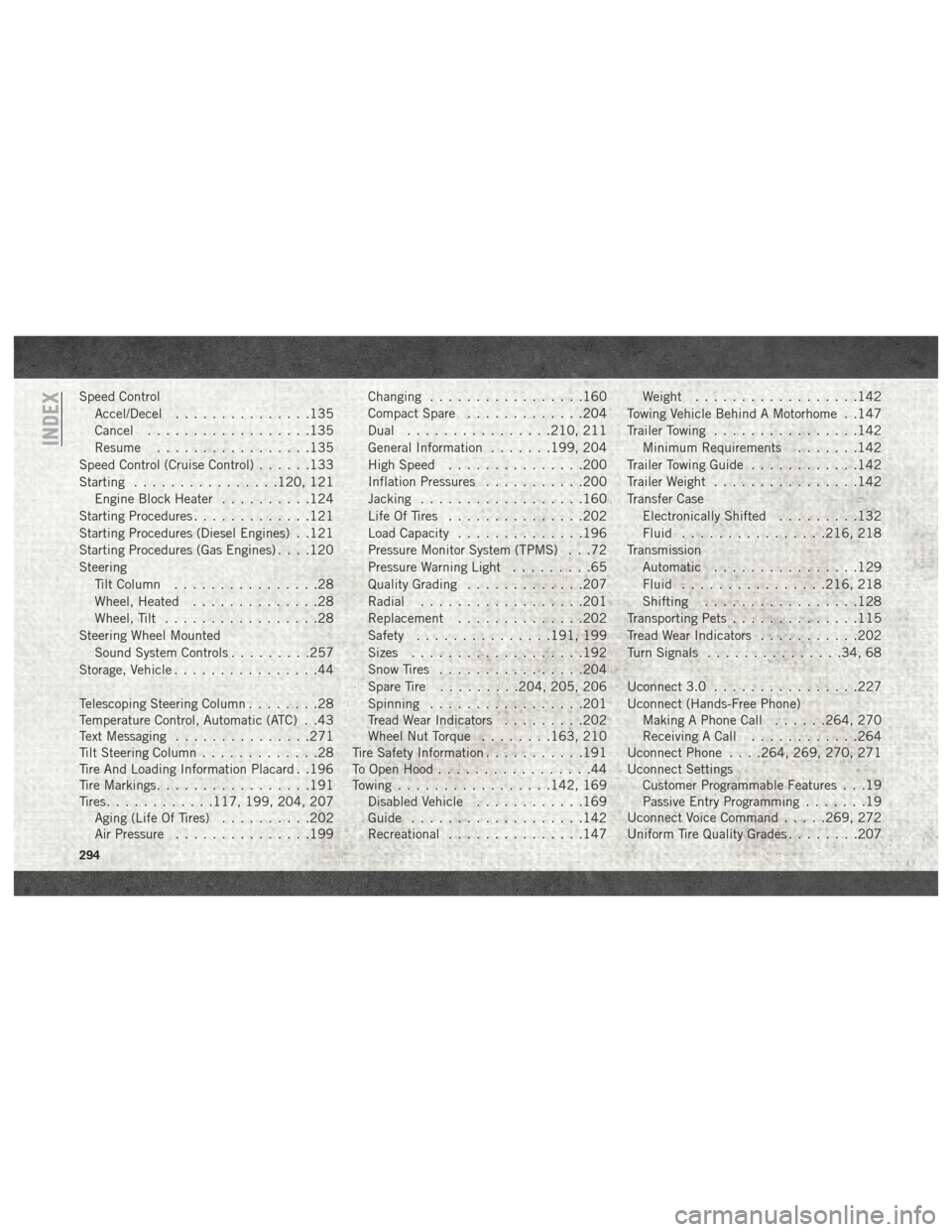
Speed ControlAccel/Decel ...............135
Cancel ..................135
Resume .................135
Speed Control (Cruise Control) ......133
Starting ................120, 121
Engine Block Heater ..........124
Starting Procedures .............121
Starting Procedures (Diesel Engines) . .121
Starting Procedures (Gas Engines) . . . .120
Steering Tilt Column ................28
Wheel, Heated ..............28
Wheel, Tilt .................28
Steering Wheel Mounted Sound System Controls .........257
Storage, Vehicle ................44
Telescoping Steering Column ........28
Temperature Control, Automatic (ATC) . .43
Text Messaging ...............271
Tilt Steering Column .............28
Tire And Loading Information Placard . .196
Tire Markings .................191
Tires ............117, 199, 204, 207
Aging (Life Of Tires) ..........202
Air Pressure ...............199 Changing
.................160
Compact Spare .............204
Dual ................210, 211
General Information .......199, 204
High Speed ...............200
Inflation Pressures ...........200
Jacking ..................160
Life Of Tires ...............202
Load Capacity ..............196
Pressure Monitor System (TPMS) . . .72
Pressure Warning Light .........65
Quality Grading .............207
Radial ..................201
Replacement ..............202
Safety ...............191, 199
Sizes ...................192
Snow Tires ................204
Spare
Tire .........204, 205, 206
Spinning .................201
Tread Wear Indicators .........202
Wheel Nut Torque ........163, 210
Tire Safety Information ...........191
To Open Hood .................44
Towing .................142, 169
Disabled Vehicle ............169
Guide ...................142
Recreational ...............147 Weight
..................142
Towing Vehicle Behind A Motorhome . .147
Trailer Towing ................142
Minimum Requirements .......142
Trailer Towing Guide ............142
Trailer Weight ................142
Transfer Case Electronically Shifted .........132
Fluid ................216, 218
Transmission Automatic ................129
Fluid ................216, 218
Shifting .................128
Transporting Pets ..............115
Tread Wear Indicators ...........202
Turn Signals ...............34, 68
Uconnect 3.0 ................227
Uconnect (Hands-Free Phone) Making A Phone Call ......264, 270
Receiving A Call ............264
Uconnect Phone . . . .264, 269, 270, 271
Uconnect Settings Customer Programmable Features . . .19
Passive Entry Programming .......19
Uconnect Voice Command .....269, 272
Uniform Tire Quality Grades ........207
INDEX
294