flat tire Ram 4500 Chassis Cab 2018 User Guide
[x] Cancel search | Manufacturer: RAM, Model Year: 2018, Model line: 4500 Chassis Cab, Model: Ram 4500 Chassis Cab 2018Pages: 298, PDF Size: 5.88 MB
Page 67 of 298
— Tire Pressure Monitoring System
(TPMS) Warning Light
The warning light switches on and a message
is displayed to indicate that the tire pressure
is lower than the recommended value and/or
that slow pressure loss is occurring. In these
cases, optimal tire duration and fuel con-
sumption may not be guaranteed.
Should one or more tires be in the condition
mentioned above, the display will show the
indications corresponding to each tire in
sequence.
CAUTION!
Do not continue driving with one or more
flat tires as handling may be compro-
mised. Stop the vehicle, avoiding sharp
braking and steering. If a tire puncture
occurs, repair immediately using the dedi-
cated tire repair kit and contact your au-
thorized dealer as soon as possible.
Each tire, including the spare (if provided),
should be checked monthly when cold and
inflated to the inflation pressure recom-
mended by the vehicle manufacturer on the vehicle placard or tire inflation pressure la-
bel. (If your vehicle has tires of a different
size than the size indicated on the vehicle
placard or tire inflation pressure label, you
should determine the proper tire inflation
pressure for those tires.)
As an added safety feature, your vehicle has
been equipped with a tire pressure monitor-
ing system (TPMS) that illuminates a low tire
pressure telltale when one or more of your
tires is significantly under-inflated. Accord-
ingly, when the low tire pressure telltale illu-
minates, you should stop and check your tires
as soon as possible, and inflate them to the
proper pressure. Driving on a significantly
under-inflated tire causes the tire to overheat
and can lead to tire failure. Under-inflation
also reduces fuel efficiency and tire tread
life, and may affect the vehicle’s handling
and stopping ability.
Please note that the TPMS is not a substitute
for proper tire maintenance, and it is the
driver’s responsibility to maintain correct tire
pressure, even if under-inflation has not
reached the level to trigger illumination of the
TPMS low tire pressure telltale.Your vehicle has also been equipped with a
TPMS malfunction indicator to indicate when
the system is not operating properly. The
TPMS malfunction indicator is combined
with the low tire pressure telltale. When the
system detects a malfunction, the telltale will
flash for approximately one minute and then
remain continuously illuminated. This se-
quence will continue upon subsequent ve-
hicle start-ups as long as the malfunction
exists. When the malfunction indicator is
illuminated, the system may not be able to
detect or signal low tire pressure as intended.
TPMS malfunctions may occur for a variety of
reasons, including the installation of replace-
ment or alternate tires or wheels on the ve-
hicle that prevent the TPMS from functioning
properly. Always check the TPMS malfunc-
tion telltale after replacing one or more tires
or wheels on your vehicle to ensure that the
replacement or alternate tires and wheels
allow the TPMS to continue to function
properly.
65
Page 74 of 298

AUXILIARY DRIVING SYSTEMS
Tire Pressure Monitoring System
(TPMS)
The Tire Pressure Monitor System (TPMS)
will warn the driver of a low tire pressure
based on the vehicle recommended cold
placard pressure.
The tire pressure will vary with temperature
by about 1 psi (7 kPa) for every 12°F (6.5°C).
This means that when the outside tempera-
ture decreases, the tire pressure will de-
crease. Tire pressure should always be set
based on cold inflation tire pressure. This is
defined as the tire pressure after the vehicle
has not been driven for at least three hours, or
driven less than 1 mile (1.6 km) after a three
hour period. The cold tire inflation pressure
must not exceed the maximum inflation pres-
sure molded into the tire sidewall. Refer to
“Tires” in “Servicing And Maintenance” for
information on how to properly inflate the
vehicle’s tires. The tire pressure will also
increase as the vehicle is driven - this is
normal and there should be no adjustment for
this increased pressure.The TPMS will warn the driver of a low tire
pressure if the tire pressure falls below the
low-pressure warning limit for any reason,
including low temperature effects and natu-
ral pressure loss through the tire.
The TPMS will continue to warn the driver of
low tire pressure as long as the condition
exists, and will not turn off until the tire
pressure is at or above the recommended
cold placard pressure. Once the low tire pres-
sure warning (Tire Pressure Monitoring [TPM]
Telltale Light) illuminates, you must increase
the tire pressure to the recommended cold
placard pressure in order for the TPM Telltale
Light to turn off. The system will automati-
cally update and the TPM Telltale Light will
turn off once the system receives the updated
tire pressures. The vehicle may need to be
driven for up to 20 minutes above 15 mph
(24 km/h) in order for the TPMS to receive
this information.
NOTE:
When filling warm tires, the tire pressure may
need to be increased up to an additional 4 psi
(30 kPa) above the recommended cold plac-
ard pressure in order to turn the Tire Pressure
Monitoring Telltale Light off.
For example, your vehicle may have a recom-
mended cold (parked for more than three
hours) placard pressure of 30 psi (207 kPa).
If the ambient temperature is 68°F (20°C)
and the measured tire pressure is 27 psi
(186 kPa), a temperature drop to 20°F (-7°C)
will decrease the tire pressure to approxi-
mately 23 psi (158 kPa). This tire pressure is
sufficiently low enough to turn on the TPM
Telltale Light. Driving the vehicle may cause
the tire pressure to rise to approximately
27 psi (186 kPa), but the TPM Telltale Light
will still be on. In this situation, the TPM
Telltale Light will turn off only after the tires
are inflated to the vehicle’s recommended
cold placard pressure value.
SAFETY
72
Page 75 of 298

CAUTION!
• The TPMS has been optimized for theoriginal equipment tires and wheels.
TPMS pressures and warning have been
established for the tire size equipped on
your vehicle. Undesirable system opera-
tion or sensor damage may result when
using replacement equipment that is not
of the same size, type, and/or style.
Aftermarket wheels can cause sensor
damage.
• Using aftermarket tire sealants may
cause the Tire Pressure Monitoring Sys-
tem (TPMS) sensor to become inoper-
able. After using an aftermarket tire
sealant it is recommended that you take
your vehicle to an authorized dealership
to have your sensor function checked.
• After inspecting or adjusting the tire
pressure always reinstall the valve stem
cap. This will prevent moisture and dirt
from entering the valve stem, which
could damage the TPMS sensor. NOTE:
• The TPMS is not intended to replace nor-
mal tire care and maintenance or to provide
warning of a tire failure or condition.
• The TPMS should not be used as a tire pressure gauge while adjusting your tire
pressure.
• Driving on a significantly under-inflated tire causes the tire to overheat and can lead to
tire failure. Under-inflation also reduces
fuel efficiency and tire tread life, and may
affect the vehicle’s handling and stopping
ability.
• The TPMS is not a substitute for proper tire maintenance, and it is the driver’s respon-
sibility to maintain correct tire pressure
using an accurate tire pressure gauge, even
if under-inflation has not reached the level
to trigger illumination of the TPM Telltale
Light.
• Seasonal temperature changes will affect tire pressure, and the TPMS will monitor
the actual tire pressure in the tire.
Premium System
The Tire Pressure Monitor System (TPMS)
uses wireless technology with wheel rim
mounted electronic sensors to monitor tire
pressure levels. Sensors, mounted to each
wheel as part of the valve stem, transmit tire
pressure readings to the receiver module.
NOTE:
It is particularly important for you to check
the tire pressure in all of the tires on your
vehicle monthly and to maintain the proper
pressure.
The TPMS consists of the following compo-
nents:
• Receiver module
• Four tire pressure monitoring sensors
• Various tire pressure monitoring systemmessages, which display in the instrument
cluster
• Tire pressure monitoring telltale light
Tire Pressure Monitoring Low Pressure Warnings
73
Page 76 of 298

The “Tire Pressure Monitoring Telltale Light”
will illuminate in the instrument cluster and
a chime will sound when tire pressure is low
in one or more of the four active road tires. In
addition, the instrument cluster will display a
graphic showing the pressure values of each
tire with the low tire pressure values in a
different color. An "Inflate to XX" message
will also be displayed.
Should this occur, you should stop as soon as
possible and inflate the tires with a low pres-
sure condition (those in a different color inthe instrument cluster graphic) to the vehi-
cle’s recommended cold placard pressure in-
flation value as shown in the "Inflate to XX"
message. Once the system receives the up-
dated tire pressures, the system will auto-
matically update, the graphic display in the
instrument cluster will return to it’s original
color, and the “Tire Pressure Monitoring Tell-
tale Light” will turn off. The vehicle may need
to be driven for up to 20 minutes above
15 mph (24 km/h) in order for the TPMS to
receive this information.
Service TPMS Warning
If a system fault is detected, the “Tire Pres-
sure Monitoring Telltale Light” will flash on
and off for 75 seconds and then remain on
solid. The system fault will also sound a
chime. In addition, the instrument cluster
will display a "SERVICE TPM SYSTEM" mes-
sage for a minimum of five seconds and then
display dashes (- -) in place of the pressure
value to indicate which sensor is not being
received.
If the ignition switch is cycled, this sequence
will repeat, providing the system fault still
exists. If the system fault no longer exists, the
“Tire Pressure Monitoring Telltale Light” will
no longer flash, and the "SERVICE TPM SYS-
TEM" message will no longer display, and a
pressure value will display in place of the
dashes. A system fault can occur due to any
of the following:
“LOW TIRE PRESSURE” Message
Tire Pressure Monitor Display
SAFETY
74
Page 119 of 298
WARNING!
control. To prevent SERIOUS INJURY or
DEATH:
• ALWAYS securely attach
your floor
mat using the floor mat fasteners. DO
NOT install your floor mat upside down
or turn your floor mat over. Lightly pull to
confirm mat is secured using the floor
mat fasteners on a regular basis.
• ALWAYS REMOVE THE EXISTING
FLOOR MAT FROM THE VEHICLE
before installing any other floor mat.
NEVER install or stack an additional
floor mat on top of an existing floor mat.
• ONLY install floor mats designed to fit
your vehicle. NEVER install a floor mat
that cannot be properly attached and
secured to your vehicle. If a floor mat
needs to be replaced, only use a FCA
approved floor mat for the specific
make, model, and year of your vehicle.
• ONLY use the driver’s side floor mat on
the driver’s side floor area. To check for
interference, with the vehicle properly
parked with the engine off, fully depress
the accelerator, the brake, and the
WARNING!
clutch pedal (if present) to check for
interference. If your floor mat interferes
with the operation of any pedal, or is not
secure to the floor, remove the floor mat
from the vehicle and place the floor mat
in your trunk.
• ONLY use the passenger’s side floor mat
on the passenger’s side floor area.
• ALWAYS make sure objects cannot fall
or slide into the driver’s side floor area
when the vehicle is moving. Objects can
become trapped under accelerator,
brake, or clutch pedals and could cause
a loss of vehicle control.
• NEVER place any objects under the floor
mat (e.g., towels, keys, etc.). These ob-
jects could change the position of the
floor mat and may cause interference
with the accelerator, brake, or clutch
pedals.
• If the vehicle carpet has been removed
and re-installed, always properly attach
carpet to the floor and check the floor
mat fasteners are secure to the vehicle
carpet. Fully depress each pedal to
WARNING!
check for interference with the accelera-
tor, brake, or clutch pedals then re-
install the floor mats.
• It is recommended to only use mild soap
and water to clean your floor mats. After
cleaning, always check your floor mat
has been properly installed and is se-
cured to your vehicle using the floor mat
fasteners by lightly pulling mat.
Periodic Safety Checks You
Should Make Outside The Vehicle
Tires
Examine tires for excessive tread wear and
uneven wear patterns. Check for stones,
nails, glass, or other objects lodged in the
tread or sidewall. Inspect the tread for cuts
and cracks. Inspect sidewalls for cuts,
cracks, and bulges. Check the wheel bolts for
tightness. Check the tires (including spare)
for proper cold inflation pressure.
117
Page 155 of 298
IN CASE OF EMERGENCY
HAZARD WARNING FLASHERS.....154
BULB REPLACEMENT ...........154
Replacement Bulbs.............154
FUSES.................... .155
Power Distribution Center.........155
JACKING AND TIRE CHANGING .....160
4500/5500 Models.............160
Preparations For Jacking ..........160
Jacking Instructions 4500 And
5500 Series .................161 To Stow The Flat Or Spare —
If Equipped
.................163
Hub Caps/Wheel Covers —
If Equipped .................163
JUMP STARTING ..............164
Preparations For Jump Start ........164
Jump Starting Procedure ..........165
IF YOUR ENGINE OVERHEATS ......166
GEAR SELECTOR OVERRIDE .......167FREEING A STUCK VEHICLE
.......168
TOWING A DISABLED VEHICLE .....169
Two-Wheel Drive Models..........170
Four-Wheel Drive Models ..........170
Emergency Tow Hooks — If Equipped . .171
ENHANCED ACCIDENT RESPONSE SYSTEM
(EARS) ................... .171
EVENT DATA RECORDER (EDR) ......171
IN CASE OF EMERGENCY
153
Page 163 of 298
4. Apply the parking brake.
5. Turn the ignition OFF.
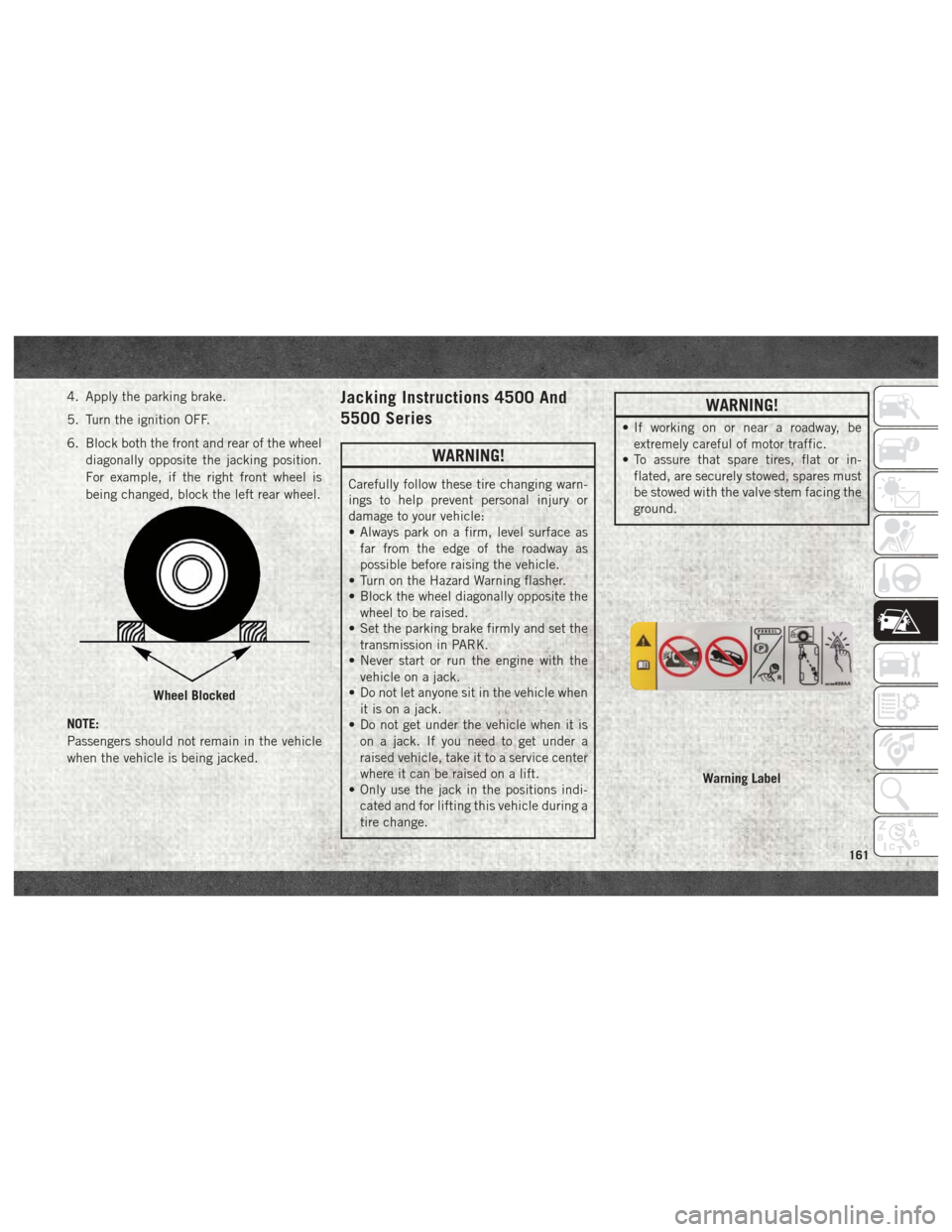
6. Block both the front and rear of the wheeldiagonally opposite the jacking position.
For example, if the right front wheel is
being changed, block the left rear wheel.
NOTE:
Passengers should not remain in the vehicle
when the vehicle is being jacked.Jacking Instructions 4500 And
5500 Series
WARNING!
Carefully follow these tire changing warn-
ings to help prevent personal injury or
damage to your vehicle:
• Always park on a firm, level surface as far from the edge of the roadway as
possible before raising the vehicle.
• Turn on the Hazard Warning flasher.
• Block the wheel diagonally opposite the
wheel to be raised.
• Set the parking brake firmly and set the
transmission in PARK.
• Never start or run the engine with the
vehicle on a jack.
• Do not let anyone sit in the vehicle when
it is on a jack.
• Do not get under the vehicle when it is
on a jack. If you need to get under a
raised vehicle, take it to a service center
where it can be raised on a lift.
• Only use the jack in the positions indi-
cated and for lifting this vehicle during a
tire change.
WARNING!
• If working on or near a roadway, beextremely careful of motor traffic.
• To assure that spare tires, flat or in-
flated, are securely stowed, spares must
be stowed with the valve stem facing the
ground.
Wheel Blocked
Warning Label
161
Page 164 of 298
CAUTION!
Do not attempt to raise the vehicle by
jacking on locations other than those indi-
cated in the Jacking Instructions for this
vehicle.
1. If equipped, remove the spare wheel, jack, and tools from storage.
2. Using the lug wrench, loosen, but do not remove, the lug nuts by turning them
counterclockwise one turn while the
wheel is still on the ground.
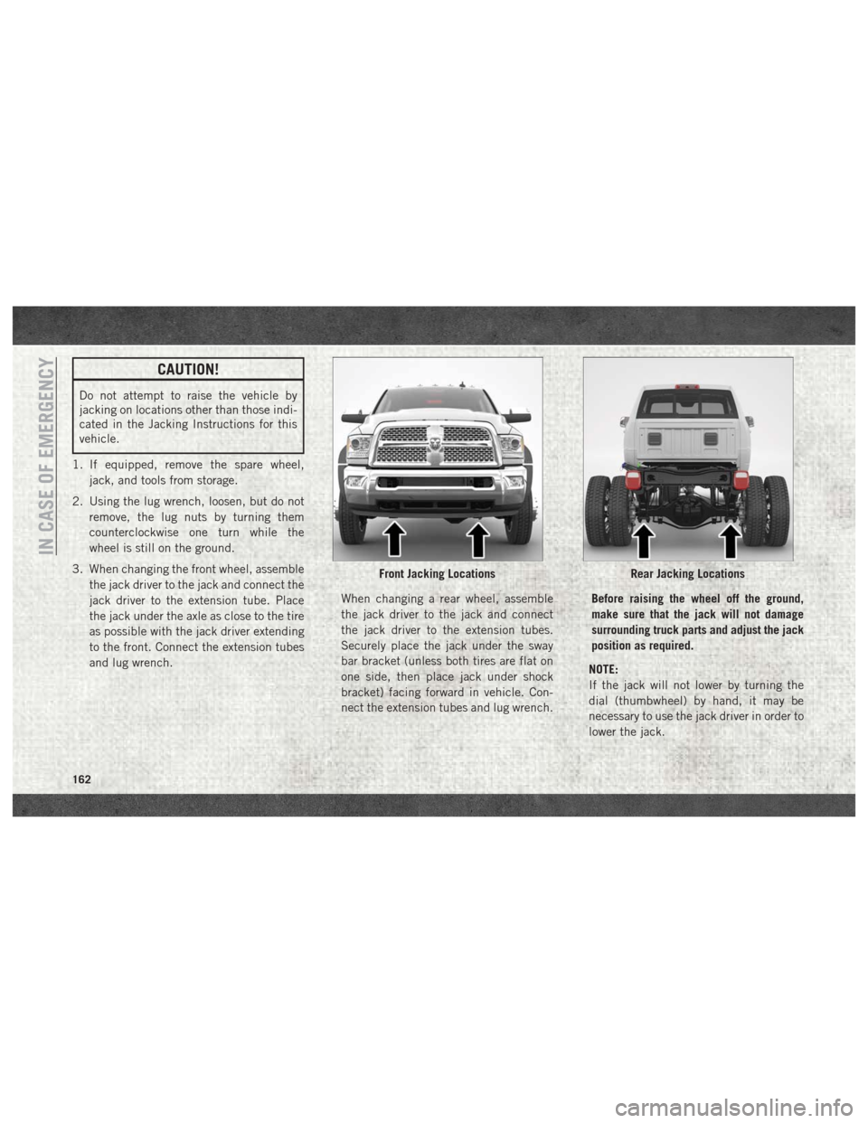
3. When changing the front wheel, assemble the jack driver to the jack and connect the
jack driver to the extension tube. Place
the jack under the axle as close to the tire
as possible with the jack driver extending
to the front. Connect the extension tubes
and lug wrench. When changing a rear wheel, assemble
the jack driver to the jack and connect
the jack driver to the extension tubes.
Securely place the jack under the sway
bar bracket (unless both tires are flat on
one side, then place jack under shock
bracket) facing forward in vehicle. Con-
nect the extension tubes and lug wrench.Before raising the wheel off the ground,
make sure that the jack will not damage
surrounding truck parts and adjust the jack
position as required.
NOTE:
If the jack will not lower by turning the
dial (thumbwheel) by hand, it may be
necessary to use the jack driver in order to
lower the jack.
Front Jacking LocationsRear Jacking Locations
IN CASE OF EMERGENCY
162
Page 165 of 298
4. By rotating the lug wrench clockwise,raise the vehicle until the wheel just
clears the surface.
WARNING!
Raising the vehicle higher than necessary
can make the vehicle less stable. It could
slip off the jack and hurt someone near it.
Raise the vehicle only enough to remove
the tire.
5. Remove the lug nuts and pull the wheel off. Install the spare wheel and lug nuts
with the cone shaped end of the nuts
toward the wheel on single rear wheel
(SRW) models. On dual rear wheel models
(DRW) the lug nuts are a two-piece assem-
bly with a flat face. Lightly tighten the
nuts. To avoid risk of forcing the vehicle
off the jack, do not fully tighten the nuts
until the vehicle has been lowered.
6. Using the lug wrench, finish tightening the nuts using a crisscross pattern. For
the proper lug nut torque specifications
refer to “Wheel And Tire Torque Specifi-
cations” in “Technical Specifications.” If
in doubt about the correct tightness, have them checked with a torque wrench by an
authorized dealer or at a service station.
WARNING!
A loose tire or jack thrown forward in a
collision or hard stop, could endanger the
occupants of the vehicle. Always stow the
jack parts and the spare tire in the places
provided.
7. Install wheel center cap (if equipped) and remove wheel blocks. Do not install
chrome or aluminum wheel center caps
on the spare wheel. This may result in cap
damage.
8. Lower the jack to its fully closed position. If the jack will not lower by turning the
dial (thumbwheel) by hand, it may be
necessary to use the jack driver in order to
lower the jack. Stow the replaced tire,
jack, and tools as previously described.
9. Adjust the tire pressure when possible.
To Stow The Flat Or Spare —
If Equipped
Refer to Upfitters Body Builders Guide for
information on stowing your spare tire (if
equipped).
Hub Caps/Wheel Covers —
If Equipped
The hub caps must be removed before raising
the vehicle off the ground.
CAUTION!
Use extreme caution when removing the
front and rear center caps. Damage can
occur to the center cap and/or the wheel if
screwdriver type tools are used. A pulling
motion, not a pry off motion, is recom-
mended to remove the caps.
For single rear wheel (SRW) models, use the
flat blade on the end of the lug wrench to pull
the hub cap off. Insert the blade end into the
pull off notch and carefully pull the hub cap
off with a back and forth motion.
163
Page 166 of 298

On 3500 models with dual rear wheels
(DRW), you must first remove the hub caps.
The jack handle driver has a hook at one end
that will fit in the pull off notch of the rear
hub caps. Position the hook and pull straight
out on the ratchet firmly. The hub cap should
pop off. The wheel skins can now be re-
moved. For the front hub cap, use the flat
blade on the end of the lug wrench to pull the
caps off. The wheel skin can now be removed.
CAUTION!
• Use a pulling motion to remove the hubcap. Do not use a twisting motion when
removing the hub cap, damage to the
hub cap; finish may occur.
• The rear hub caps on the dual rear wheel
has two pull off notches. Make sure that
the hook of the jack handle driver is
located squarely in the cap notch before
attempting to pull off.
You must use the flat end of the lug wrench to
pull off the wheel skins. Locate the hub cap
pull notches (2 notches on each cap). Insert the flat tip completely and using a back and
forth motion, loosen the wheel skin. Repeat
this procedure around the tire until the skin
pops off.
Replace the wheel skins first using a rubber
mallet. When replacing the hub caps, tilt the
cap retainer over the lug nut bolt circle and
strike the high side down with a rubber mal-
let. Be sure that the hub caps and wheel
skins are firmly seated around the wheel.
JUMP STARTING
If your vehicle has a discharged battery, it can
be jump started using a set of jumper cables
and a battery in another vehicle, or by using a
portable battery booster pack. Jump starting
can be dangerous if done improperly, so
please follow the procedures in this section
carefully.
WARNING!
Do not attempt jump starting if the battery
is frozen. It could rupture or explode and
cause personal injury.
CAUTION!
Do not use a portable battery booster pack
or any other booster source with a system
voltage greater than 12 Volts or damage to
the battery, starter motor, alternator or
electrical system may occur.
NOTE:
When using a portable battery booster pack,
follow the manufacturer's operating instruc-
tions and precautions.
Preparations For Jump Start
The battery in your vehicle is located in the
front of the engine compartment, behind the
left headlight assembly.
IN CASE OF EMERGENCY
164