reset Ram 4500 Chassis Cab 2018 User Guide
[x] Cancel search | Manufacturer: RAM, Model Year: 2018, Model line: 4500 Chassis Cab, Model: Ram 4500 Chassis Cab 2018Pages: 298, PDF Size: 5.88 MB
Page 23 of 298
The vehicle doors can also be locked by using
the key fob lock button or the lock button
located on the vehicle’s interior door panel.
General Information
The following regulatory statement applies to
all radio frequency (RF) devices equipped in
this vehicle:
This device complies with Part 15 of the FCC
Rules and with Industry Canada license-
exempt RSS standard(s). Operation is sub-
ject to the following two conditions:
1. This device may not cause harmful inter-ference, and
2. This device must accept any interference received, including interference that may
cause undesired operation.
NOTE:
Changes or modifications not expressly ap-
proved by the party responsible for compli-
ance could void the user’s authority to oper-
ate the equipment.
SEATS
Seats are a part of the Occupant Restraint
System of the vehicle.
WARNING!
• It is dangerous to ride in a cargo area, inside or outside of a vehicle. In a colli-
sion, people riding in these areas are
more likely to be seriously injured or
killed.
• Do not allow people to ride in any area of
your vehicle that is not equipped with
seats and seat belts. In a collision,
people riding in these areas are more
likely to be seriously injured or killed.
• Be sure everyone in your vehicle is in a
seat and using a seat belt properly.
Driver Memory Seat — If Equipped
This feature allows the driver to store up to
two different memory profiles for easy recall
through a memory switch. Each memory pro-
file contains desired position settings for the
driver’s seat, side mirrors, adjustable pedals
(if equipped) and a set of desired radio sta- tion presets. Your remote keyless entry key
fob can also be programmed to recall the
same positions when the unlock button is
pushed.
NOTE:
Your vehicle is equipped with two key fobs,
one key fob can be linked to memory position
1 and the other key fob can be linked to
memory position 2.
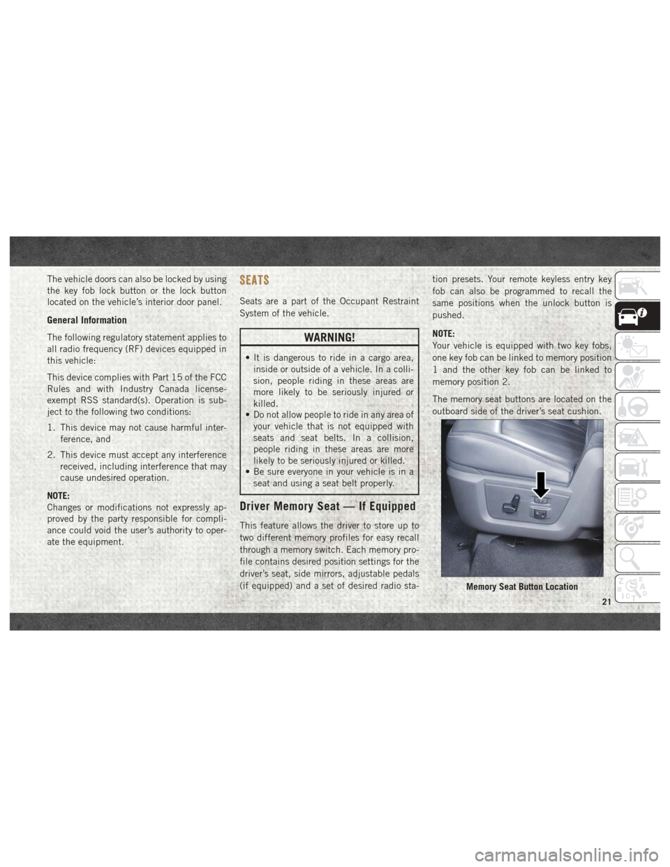
The memory seat buttons are located on the
outboard side of the driver’s seat cushion.
Memory Seat Button Location
21
Page 24 of 298
Programming The Memory Feature
To create a new memory profile, perform the
following:
1. Cycle the vehicle’s ignition to the ON/RUN position (do not start the engine).
2. Adjust all memory profile settings to de- sired preferences (i.e., driver’s seat, out-
side mirrors and radio station presets).
3. Push and release the set (S) button on the memory switch.
4. Within five seconds, push and release either of the memory buttons (1) or (2).
The instrument cluster display will show
which memory position has been set.
NOTE:
• Memory profiles can be set without the vehicle in PARK, but the vehicle must be in
PARK to recall a memory profile.
• To set a memory profile to your key fob, refer to “Linking And Unlinking The Re-
mote Keyless Entry Key Fob To Memory” in
this section.
Linking And Unlinking The Remote Keyless
Entry Key Fob To Memory
Your key fobs can be programmed to recall
one of two pre-programmed memory profiles
by pushing the unlock button on the key fob.
NOTE:
Before programming your key fobs to memory
the feature has to be selected.
• If your vehicle is equipped with a touch-screen, you must select the “Memory To
Fob” feature through the Uconnect system.
Refer to “Uconnect Settings” in “Multimedia”
in the Owner’s Manual at
www.mopar.com/
en-us/care/owners-manual.html (U.S.
Residents) or www.owners.mopar.ca
(Canadian Residents) for further information.
• If your vehicle is not equipped with a touch- screen, you must select the “Key Fob
Linked To Memory” feature through the
instrument cluster display. Refer to “In-
strument Cluster Display” in “Getting To
Know Your Instrument Panel” in the Own-
er’s Manual at www.mopar.com/en-us/
care/owners-manual.html (U.S. Residents)
or www.owners.mopar.ca (Canadian
Residents) for further information. To program your key fobs, perform the follow-
ing:
1. Cycle the vehicle’s ignition to the OFF
position.
2. Select desired memory profile (1) or (2).
NOTE:
If a memory profile has not already been
set, refer to "Programming The Memory
Feature" for instructions on how to set a
memory profile.
3. Once the profile has been recalled, push and release the set (S) button on the
memory switch, then push and release
button (1) or (2) accordingly. “Memory
Profile Set” (1 or 2) will display in the
instrument cluster display.
4. Push and release the lock button on the key fob within 10 seconds.
NOTE:
Your key fobs can be unlinked to your memory
settings by pushing the set (S) button, and
within 10 seconds, followed by pushing the
unlock button on the key fob.GETTING TO KNOW YOUR VEHICLE
22
Page 32 of 298
• For vehicles equipped with Driver MemorySeat, you can use your remote keyless entry
key fob or the memory switch on the driver’s
door trim panel to return the adjustable
pedals to pre-programmed positions. Refer
to “Driver Memory Seat” in “Getting To
Know Your Vehicle” for further information.
WARNING!
Do not adjust the pedals while the vehicle
is moving. You could lose control and have
an accident. Always adjust the pedals
while the vehicle is parked.
CAUTION!
Do not place any article under the adjust-
able pedals or impede its ability to move,
as it may cause damage to the pedal con-
trols. Pedal travel may become limited if
movement is stopped by an obstruction in
the adjustable pedal's path.
MIRRORS
Power Folding Outside Mirrors For
Standard And Trailer Tow —
If Equipped
If equipped with power folding mirrors, they
can be electrically folded rearward and un-
folded into the drive position.
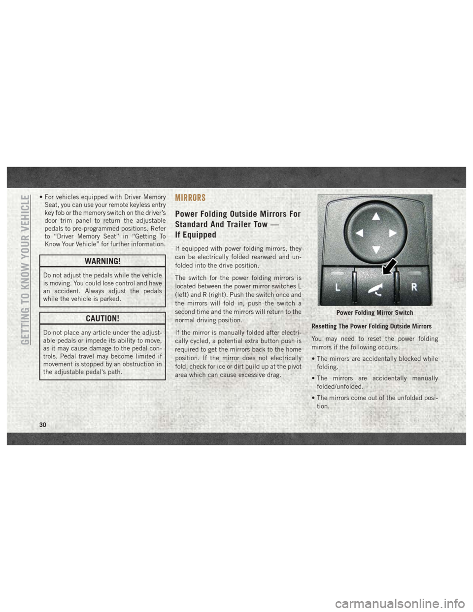
The switch for the power folding mirrors is
located between the power mirror switches L
(left) and R (right). Push the switch once and
the mirrors will fold in, push the switch a
second time and the mirrors will return to the
normal driving position.
If the mirror is manually folded after electri-
cally cycled, a potential extra button push is
required to get the mirrors back to the home
position. If the mirror does not electrically
fold, check for ice or dirt build up at the pivot
area which can cause excessive drag. Resetting The Power Folding Outside Mirrors
You may need to reset the power folding
mirrors if the following occurs:
• The mirrors are accidentally blocked while
folding.
• The mirrors are accidentally manually folded/unfolded.
• The mirrors come out of the unfolded posi- tion.
Power Folding Mirror Switch
GETTING TO KNOW YOUR VEHICLE
30
Page 33 of 298
• The mirrors shake and vibrate at normaldriving speeds.
To Reset The Power Folding Mirrors:
1. Using the power folding mirror switch, move the mirror to its full forward
position.
2. Using the power folding mirror switch, move the mirror to the full retract position
(this may require multiple button
pushes). This resets them to their normal
position.
NOTE:
• The power fold mirrors are designed to operate while the vehicle is stationary or
traveling at moderate speeds. If you at-
tempt to power fold the mirrors at high
speeds they may not fully open or close. You
should slow down to a moderate speed and
complete the operation.
• When pushing the power fold button 10 or more times in one minute the system shuts
down for one minute to protect the motors
from over heating.EXTERIOR LIGHTS
Headlight Switch
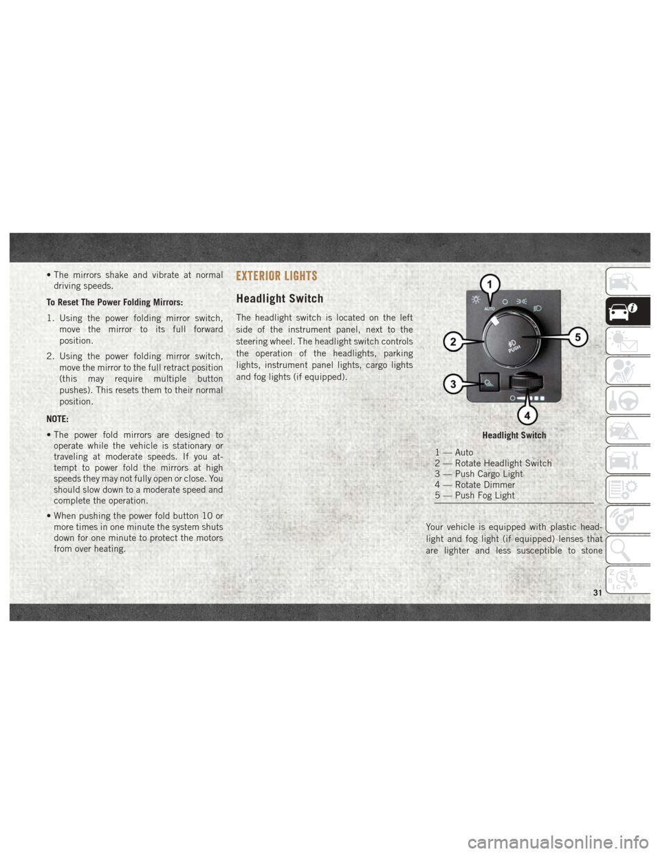
The headlight switch is located on the left
side of the instrument panel, next to the
steering wheel. The headlight switch controls
the operation of the headlights, parking
lights, instrument panel lights, cargo lights
and fog lights (if equipped).
Your vehicle is equipped with plastic head-
light and fog light (if equipped) lenses that
are lighter and less susceptible to stone
Headlight Switch
1 — Auto
2 — Rotate Headlight Switch
3 — Push Cargo Light
4 — Rotate Dimmer
5 — Push Fog Light
31
Page 53 of 298

CAUTION!
quickly. Only use these intermittently
and with greater caution.
• After the use of high power draw acces-
sories, or long periods of the vehicle not
being started (with accessories still
plugged in), the vehicle must be driven a
sufficient length of time to allow the
generator to recharge the vehicle's bat-
tery.
Power Inverter — If Equipped
A 115 or 230 Volt (150 Watts Maximum)
outlet is located on the center stack of the
instrument panel, to the right of the radio.
This outlet can power cellular phones, elec-
tronics and other low power devices requiring
power up to 150 Watts. Certain high-end
video game consoles will exceed this power
limit, as will most power tools. The power inverter is designed with built-in
overload protection. If the power rating of
150 Watts is exceeded, the power inverter
will automatically shut down. Once the elec-
trical device has been removed from the out-
let the inverter should automatically reset.
To turn on the power outlet, simply plug in the
device. The outlet automatically turns off
when the device is unplugged.
NOTE:
• The Power Inverter will only turn on if the
ignition is in the ACC or ON/RUN position
• Due to built-in overload protection, the power inverter will shut down if the power
rating is exceeded.
WARNING!
To avoid serious injury or death:
• Do not insert any objects into the
receptacles.
• Do not touch with wet hands.
• Close the lid when not in use.
• If this outlet is mishandled, it may cause
an electric shock and failure.
Power Inverter
51
Page 55 of 298

GETTING TO KNOW YOUR INSTRUMENT PANEL
INSTRUMENT CLUSTER DISPLAY.....54
Instrument Cluster Display Controls ....54
Diesel Messages And Warnings —
6.7L Cummins Diesel Engine ........55
Oil Life Reset .................59
Instrument Cluster Display
Programmable Features ...........59
WARNING LIGHTS AND MESSAGES ....61
Red Warning Lights..............61
Yellow Warning Lights ............63
Yellow Indicator Lights ............67
Green Indicator Lights ............68
White Indicator Lights ............68
Blue Indicator Lights .............68
ONBOARD DIAGNOSTIC SYSTEM —
OBDII .....................69
Onboard Diagnostic System (OBD II)
Cybersecurity.................69
GETTING TO KNOW YOUR INSTRUMENT PANEL
53
Page 57 of 298

• Push and release thedownarrow button to
scroll downward through the main menu
items, submenu screen, and vehicle set-
tings.
• Push and release the rightarrow button to
access/select the information screens or
submenu screens of a main menu item.
Push and hold the RIGHT arrow button for
two seconds to reset displayed/selected
features that can be reset.
• Push and release the leftarrow button to
access/select the information screens, sub-
menu screens of a main menu item, or to
return to the main menu.
Diesel Messages And Warnings —
6.7L Cummins Diesel Engine
Diesel Particulate Filter (DPF) Messages
The Cummins diesel engine meets all diesel
emissions standards, resulting in one of the
lowest emitting diesel engines ever pro-
duced. To achieve these emissions stan-
dards, your vehicle is equipped with a state-
of-the-art engine and exhaust system. These
systems are seamlessly integrated into your vehicle and managed by the Powertrain Con-
trol Module (PCM). The PCM manages engine
combustion to allow the exhaust system’s
catalyst to trap and burn Particulate Matter
(PM) pollutants, with no input or interaction
on your part.
WARNING!
A hot exhaust system can start a fire if you
park over materials that can burn. Such
materials might be grass or leaves coming
into contact with your exhaust system. Do
not park or operate your vehicle in areas
where your exhaust system can contact
anything that can burn.
Your vehicle has the ability to alert you to
additional maintenance required on your ve-
hicle or engine. The following messages may
display in your instrument cluster display:
• Perform Service — Your vehicle will require
emissions maintenance at a set interval. To
help remind you when this maintenance is
due, the instrument cluster display will
display “Perform Service”. When the “Per-
form Service” message is displayed in the
instrument cluster display it is necessary to have the emissions maintenance per-
formed. Emissions maintenance may in-
clude replacing the Closed Crankcase Ven-
tilation (CCV) filter element. The procedure
for clearing and resetting the "Perform Ser-
vice" indicator message is located in the
appropriate Service Information.
• Exhaust System — Regeneration Required
Now — "Exhaust Filter XX% Full Safely
Drive at Highway Speeds to Remedy" will be
displayed in the instrument cluster display
if the exhaust particulate filter reaches
80% of its maximum storage capacity. Un-
der conditions of exclusive short duration
and low speed driving cycles, your Cum-
mins diesel engine and exhaust after-
treatment system may never reach the con-
ditions required to remove the trapped PM.
If this occurs, the “Exhaust Filter XX% Full
Safely Drive at Highway Speeds to Rem-
edy” message will be displayed in the in-
strument cluster display. If this message is
displayed, you will hear one chime to assist
in alerting you of this condition
By simply driving your vehicle at highway
speeds for as little as 45 minutes, you can
remedy the condition in the particulate filter
55
Page 58 of 298

system and allow your Cummins diesel en-
gine and exhaust after-treatment system to
remove the trapped PM and restore the sys-
tem to normal operating condition.
•Exhaust System — Regeneration In Process
Exhaust Filter XX% Full — Indicates that the
Diesel Particulate Filter (DPF) is self-
cleaning. Maintain your current driving
condition until regeneration is completed.
• Exhaust System — Regeneration Completed
— This message indicates that the Diesel
Particulate Filter (DPF) self-cleaning is
completed. If this message is displayed,
you will hear one chime to assist in alerting
you of this condition.
• Exhaust Service Required — See Dealer Now
— This message indicates regeneration has
been disabled due to a system malfunction.
At this point the engine Powertrain Control
Module (PCM) will register a fault code, the
instrument panel will display a MIL light.CAUTION!
See your authorized dealer, as damage to
the exhaust system could occur soon with
continued operation.
• Exhaust Filter Full — Power Reduced See
Dealer — This message indicates the PCM
has derated the engine to limit the likeli-
hood of permanent damage to the after-
treatment system. If this condition is not
corrected and a dealer service is not per-
formed, extensive exhaust after-treatment
damage can occur. To correct this condition
it will be necessary to have your vehicle
serviced by your local authorized dealer.
NOTE:
Failing to follow the oil change indicator,
changing your oil and resetting the oil change
indicator by 0 miles remaining will prevent
the diesel exhaust filter from performing it's
cleaning routine. This will shortly result in a
Malfunction Indicator Light (MIL) and re-
duced engine power. Only an authorized
dealer will be able to correct this condition.
CAUTION!
See your authorized dealer, as damage to
the exhaust system could occur soon with
continued operation.
Cold Ambient Derate Mode Messages
The vehicle will display messages when a
derate (engine power reduction) is activated
to protect the turbocharger during engine
start up in cold ambient temperatures.
• Engine Power Reduced During Warmup —
This message will display during start up
when the ambient temperature is between
10° F (-12° C) and -10° F (-23° C).
• Engine Power Reduced Up To 30 Sec (Sec-
onds) During Warmup — This message will
display during start up when the ambient
temperature is between -10° F (-23° C) and
-25 F (-32° C).
• Engine Power Reduced Up To 2 Min (Minutes)
During Warmup — This message will display
during start up when the ambient tempera-
ture is -25° F (-32° C) and below.
GETTING TO KNOW YOUR INSTRUMENT PANEL
56
Page 61 of 298
under demanding hot or high altitude condi-
tions. If the instrument cluster display dis-
plays the message “Active Airbox Service
Required See Dealer”, vehicle performance
may be reduced until service is performed by
an authorized RAM dealer.
Oil Life Reset
Your vehicle is equipped with an engine oil
change indicator system. The “Oil Change
Required” message will display in the instru-
ment cluster display after a single chime has
sounded, to indicate the next scheduled oil
change interval. The engine oil change indi-
cator system is duty cycle based, which
means the engine oil change interval may
fluctuate, dependent upon your personal
driving style.
NOTE:
Use the steering wheel instrument cluster
display controls for the following proce-
dure(s).Vehicles Equipped With Passive Entry
1. Without pushing the brake pedal, push
the ENGINE START/STOP button and
place the ignition to the ON/RUN position
(do not start the engine).
2. Push and release the downarrow button to
scroll downward through the main menu
to “Vehicle Info.”
3. Push and release the rightarrow button to
access the ”Vehicle Info” screen, then
scroll up or down to select “Oil Life.”
4. Push and hold the rightarrow button to
select “Reset”.
5. Push and release the downarrow button to
select “Yes,” then push and release the
right arrow button to select reset of the Oil
Life to 100%.
6. Push and release the uparrow button to
exit the instrument cluster display screen. Vehicles Not Equipped With Passive Entry
1. Without pushing the brake pedal, cycle
the ignition to the ON/RUN position (do
not start the engine).
2. Push and release the downarrow button to
scroll downward through the main menu
to “Vehicle Info.”
3. Push and release the rightarrow button to
access the “Vehicle Info” screen then
scroll up or down to select “Oil Life.”
4. Push and hold the rightarrow button to
select “YES” by pushing the rightarrow
then push and release the rightarrow
button to select reset of the Oil Life to
100%.
5. Push and release the uparrow button to
exit the instrument cluster display screen.
NOTE:
If the indicator message illuminates when
you start the vehicle, the Oil Life indicator
system did not reset. If necessary, repeat this
procedure.
59
Page 97 of 298
Enhanced Accident Response System Reset
Procedure
In order to reset the Enhanced Accident Re-
sponse System functions after an event, the
ignition switch must be changed from igni-
tion START or ON/RUN to ignition OFF. Care-
fully check the vehicle for fuel leaks in the
engine compartment and on the ground near
the engine compartment and fuel tank before
resetting the system and starting the engine.
Maintaining Your Air Bag System
WARNING!
• Modifications to any part of the air bagsystem could cause it to fail when you
need it. You could be injured if the air
bag system is not there to protect you.
Do not modify the components or wiring,
including adding any kind of badges or
stickers to the steering wheel hub trim
cover or the upper right side of the in-
strument panel. Do not modify the front
bumper, vehicle body structure, or add
aftermarket side steps or running
boards.
WARNING!
• It is dangerous to try to repair any part ofthe air bag system yourself. Be sure to
tell anyone who works on your vehicle
that it has an air bag system.
• Do not attempt to modify any part of your
air bag system. The air bag may inflate
accidentally or may not function prop-
erly if modifications are made. Take your
vehicle to an authorized dealer for any
air bag system service. If your seat, in-
cluding your trim cover and cushion,
needs to be serviced in any way (includ-
ing removal or loosening/tightening of
seat attachment bolts), take the vehicle
to your authorized dealer. Only manufac-
turer approved seat accessories may be
used. If it is necessary to modify the air
bag system for persons with disabilities,
contact your authorized dealer.
Event Data Recorder (EDR)
This vehicle is equipped with an event data
recorder (EDR). The main purpose of an EDR
is to record, in certain crash or near crash-like
situations, such as an air bag deployment or
hitting a road obstacle, data that will assist in
understanding how a vehicle’s systems per-
formed. The EDR is designed to record data
related to vehicle dynamics and safety sys-
tems for a short period of time, typically
30 seconds or less. The EDR in this vehicle is
designed to record such data as:
• How various systems in your vehicle were
operating;
• Whether or not the driver and passenger safety belts were buckled/fastened;
• How far (if at all) the driver was depressing the accelerator and/or brake pedal; and,
• How fast the vehicle was traveling.
These data can help provide a better under-
standing of the circumstances in which
crashes and injuries occur.
95