jump start Ram 4500 Chassis Cab 2018 User Guide
[x] Cancel search | Manufacturer: RAM, Model Year: 2018, Model line: 4500 Chassis Cab, Model: Ram 4500 Chassis Cab 2018Pages: 298, PDF Size: 5.88 MB
Page 155 of 298
IN CASE OF EMERGENCY
HAZARD WARNING FLASHERS.....154
BULB REPLACEMENT ...........154
Replacement Bulbs.............154
FUSES.................... .155
Power Distribution Center.........155
JACKING AND TIRE CHANGING .....160
4500/5500 Models.............160
Preparations For Jacking ..........160
Jacking Instructions 4500 And
5500 Series .................161 To Stow The Flat Or Spare —
If Equipped
.................163
Hub Caps/Wheel Covers —
If Equipped .................163
JUMP STARTING ..............164
Preparations For Jump Start ........164
Jump Starting Procedure ..........165
IF YOUR ENGINE OVERHEATS ......166
GEAR SELECTOR OVERRIDE .......167FREEING A STUCK VEHICLE
.......168
TOWING A DISABLED VEHICLE .....169
Two-Wheel Drive Models..........170
Four-Wheel Drive Models ..........170
Emergency Tow Hooks — If Equipped . .171
ENHANCED ACCIDENT RESPONSE SYSTEM
(EARS) ................... .171
EVENT DATA RECORDER (EDR) ......171
IN CASE OF EMERGENCY
153
Page 166 of 298

On 3500 models with dual rear wheels
(DRW), you must first remove the hub caps.
The jack handle driver has a hook at one end
that will fit in the pull off notch of the rear
hub caps. Position the hook and pull straight
out on the ratchet firmly. The hub cap should
pop off. The wheel skins can now be re-
moved. For the front hub cap, use the flat
blade on the end of the lug wrench to pull the
caps off. The wheel skin can now be removed.
CAUTION!
• Use a pulling motion to remove the hubcap. Do not use a twisting motion when
removing the hub cap, damage to the
hub cap; finish may occur.
• The rear hub caps on the dual rear wheel
has two pull off notches. Make sure that
the hook of the jack handle driver is
located squarely in the cap notch before
attempting to pull off.
You must use the flat end of the lug wrench to
pull off the wheel skins. Locate the hub cap
pull notches (2 notches on each cap). Insert the flat tip completely and using a back and
forth motion, loosen the wheel skin. Repeat
this procedure around the tire until the skin
pops off.
Replace the wheel skins first using a rubber
mallet. When replacing the hub caps, tilt the
cap retainer over the lug nut bolt circle and
strike the high side down with a rubber mal-
let. Be sure that the hub caps and wheel
skins are firmly seated around the wheel.
JUMP STARTING
If your vehicle has a discharged battery, it can
be jump started using a set of jumper cables
and a battery in another vehicle, or by using a
portable battery booster pack. Jump starting
can be dangerous if done improperly, so
please follow the procedures in this section
carefully.
WARNING!
Do not attempt jump starting if the battery
is frozen. It could rupture or explode and
cause personal injury.
CAUTION!
Do not use a portable battery booster pack
or any other booster source with a system
voltage greater than 12 Volts or damage to
the battery, starter motor, alternator or
electrical system may occur.
NOTE:
When using a portable battery booster pack,
follow the manufacturer's operating instruc-
tions and precautions.
Preparations For Jump Start
The battery in your vehicle is located in the
front of the engine compartment, behind the
left headlight assembly.
IN CASE OF EMERGENCY
164
Page 167 of 298
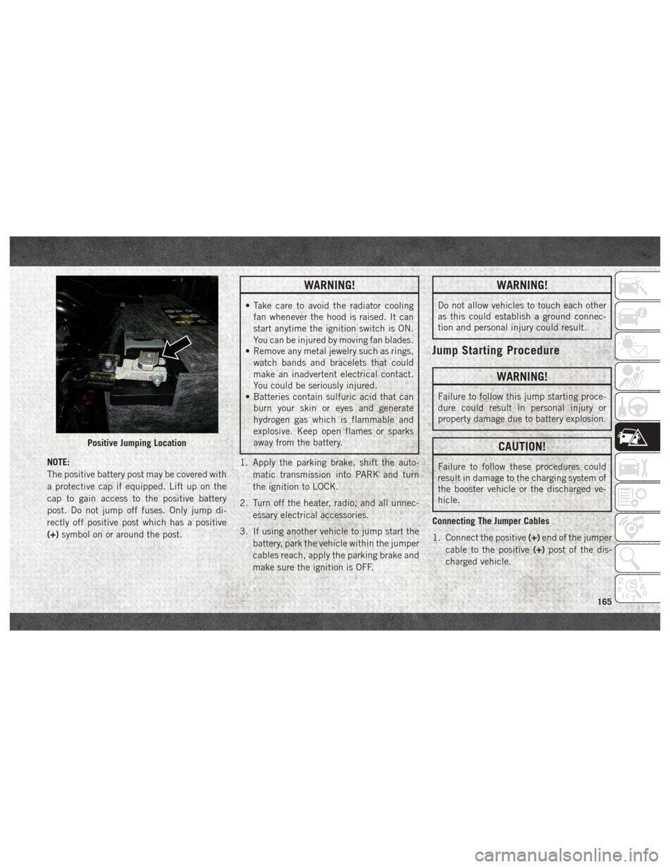
NOTE:
The positive battery post may be covered with
a protective cap if equipped. Lift up on the
cap to gain access to the positive battery
post. Do not jump off fuses. Only jump di-
rectly off positive post which has a positive
(+)symbol on or around the post.
WARNING!
• Take care to avoid the radiator cooling
fan whenever the hood is raised. It can
start anytime the ignition switch is ON.
You can be injured by moving fan blades.
• Remove any metal jewelry such as rings,
watch bands and bracelets that could
make an inadvertent electrical contact.
You could be seriously injured.
• Batteries contain sulfuric acid that can
burn your skin or eyes and generate
hydrogen gas which is flammable and
explosive. Keep open flames or sparks
away from the battery.
1. Apply the parking brake, shift the auto- matic transmission into PARK and turn
the ignition to LOCK.
2. Turn off the heater, radio, and all unnec- essary electrical accessories.
3. If using another vehicle to jump start the battery, park the vehicle within the jumper
cables reach, apply the parking brake and
make sure the ignition is OFF.
WARNING!
Do not allow vehicles to touch each other
as this could establish a ground connec-
tion and personal injury could result.
Jump Starting Procedure
WARNING!
Failure to follow this jump starting proce-
dure could result in personal injury or
property damage due to battery explosion.
CAUTION!
Failure to follow these procedures could
result in damage to the charging system of
the booster vehicle or the discharged ve-
hicle.
Connecting The Jumper Cables
1. Connect the positive (+)end of the jumper
cable to the positive (+)post of the dis-
charged vehicle.
Positive Jumping Location
165
Page 168 of 298

NOTE:
Do not jump off fuses. Only jump directly off
positive post.
2. Connect the opposite end of the positive (+) jumper cable to the positive (+)post of
the booster battery.
3. Connect the negative (-)end of the jumper
cable to the negative (-)post of the
booster battery.
4. Connect the opposite end of the negative (-)jumper cable to a good engine ground
(exposed metal part of the discharged
vehicle’s engine) away from the battery
and the fuel injection system.
WARNING!
Do not connect the jumper cable to the
negative (-) post of the discharged battery.
The resulting electrical spark could cause
the battery to explode and could result in
personal injury. Only use the specific
ground point, do not use any other exposed
metal parts. 5. Start the engine in the vehicle that has
the booster battery, let the engine idle a
few minutes, and then start the engine in
the vehicle with the discharged battery.
CAUTION!
Do not connect jumper cable to any of the
fuses on the positive battery terminal. The
resulting electrical current will blow the
fuse.
6. Once the engine is started, remove the jumper cables in the reverse sequence:
Disconnecting The Jumper Cables
1. Disconnect the negative (-)end of the
jumper cable from the engine ground of
the vehicle with the discharged battery.
2. Disconnect the opposite end of the nega- tive (-)jumper cable from the negative (-)
post of the booster battery.
3. Disconnect the positive (+)end of the
jumper cable from the positive (+)post of
the booster battery. 4. Disconnect the opposite end of the posi-
tive (+)jumper cable from the positive (+)
post of the vehicle with the discharged
battery.
If frequent jump starting is required to start
your vehicle you should have the battery and
charging system inspected at an authorized
dealer.
CAUTION!
Accessories plugged into the vehicle
power outlets draw power from the vehi-
cle’s battery, even when not in use (i.e.,
cellular devices, etc.). Eventually, if
plugged in long enough without engine
operation, the vehicle’s battery will dis-
charge sufficiently to degrade battery life
and/or prevent the engine from starting.
IF YOUR ENGINE OVERHEATS
In any of the following situations, you can
reduce the potential for overheating by taking
the appropriate action.
• On the highways — slow down.
IN CASE OF EMERGENCY
166
Page 237 of 298
Browse
Press the “Browse” button on the touch-
screen to scroll through and select a desired
track on the Disc. Press the “Exit” button on
the touchscreen if you wish to cancel the
browse function.
Eject Button — Ejecting a Disc
Push the eject button to eject the disc. If you
have ejected a disc and have not removed it
within ten seconds, it will be reloaded. If the
Disc is not removed, the radio will reinsert the
disc but will not play it.
A disc can be ejected with the radio and
ignition OFF.
USB/iPod Mode
USB/iPod Mode is entered by either inserting
a USB Jump Drive or iPod cable into the USB
port, or by pushing the MEDIA button located
on the faceplate. Once in Media Mode, press
the “Source” button on the touchscreen and
select “USB/iPod.”Inserting USB/iPod Device
Gently insert the USB/iPod device into the
USB Port. If you insert a USB/iPod device
with the ignition ON, the unit will switch to
USB/iPod mode and begin to play when you
insert the device. The display will show the
track number and index time in minutes and
seconds. Play will begin at the start of track
one.
Browse
Press the “Browse” button on the touch-
screen to select Artist, Albums, Genres,
Songs, Playlists or Folders from the USB/
iPod device. Once the desired selection is
made you can chose from the available media
by pressing the button on the touchscreen.
Press the “Exit” button on the touchscreen if
you wish to cancel the browse function.
AUX Mode
AUX Mode is entered by inserting a AUX
device using a stereo cable with a 3.5 mm
audio jack into the AUX port, or by pushing
the MEDIA button located on the faceplate.
Once in Media Mode, press the “Source”
button on the touchscreen and select “AUX.”Inserting Auxiliary Device
Gently insert the Auxiliary device cable into
the AUX Port. If you insert a Auxiliary device
with the ignition ON, the unit will switch to
AUX mode and begin to play when you insert
the device cable.
Controlling The Auxiliary Device
The control of the Auxiliary device (e.g., se-
lecting playlists, play, fast forward, etc.) can-
not be provided by the radio; use the device
controls instead. Adjust the volume with the
VOLUME/MUTE rotary knob, or with the vol-
ume of the attached device.
The vehicle radio unit is acting as the ampli-
fier for audio output from the Auxiliary de-
vice. Therefore if the volume control on the
Auxiliary device is set too low, there will be
insufficient audio signal for the radio unit to
play the music on the device.
235
Page 292 of 298
Lower Anchors And Tethers
For Children...............101
Older Children And Child
Restraints .................98
Seating Positions ............100
Cleaning Wheels ..................206
Climate Control ................37
Manual ...................37
Clock .....................231
Clock Setting .................231
Compact Spare Tire .............204
Contract, Service ..............285
Cooling System Coolant Capacity ............213
Selection Of Coolant
(Antifreeze) ............214, 216
Cruise Light ..................68
Customer Assistance ............284
Customer Programmable Features . . . .256
Dealer Service ................186
Defroster, Windshield ............116
Delay (Intermittent) Wipers .........35
Diagnostic System, Onboard ........69
Diesel Fuel System, Re-Priming .....190
Disabled Vehicle Towing ..........169Disturb
....................270
Door Ajar ....................62
Door Ajar Light ................62
Draining Fuel/Water Separator Filter . . .187
Driver's Seat Back Tilt ............21
Dual Rear Wheels ..........210, 211
Electrical Power Outlets ...........49
Electronically Shifted Transfer Case . . .132
Electronic Range Select (ERS) ......131
Electronic Speed Control (Cruise Control) ..............133
Electronic Throttle Control Warning Light ...............62
Emergency, In Case Of Freeing Vehicle When Stuck .....168
Hazard Warning Flasher ........154
Jacking ..................160
Jump Starting ..............164
Engine .................184, 185
Air Cleaner ............... .186
Block
Heater ...............124
Break-In Recommendations .....127
Compartment ..............185
Compartment Identification ......184
Coolant (Antifreeze) .......214, 216
Exhaust Gas Caution ..........115 Identification
..............185
Idling ...................125
Jump Starting ..............164
Oil .................214, 216
Oil Filler Cap ..............184
Overheating ...............166
Enhanced Accident Response Feature ................94, 171
Exhaust Gas Caution ............115
Exhaust System ...............115
Exterior Lighting ...............31
Exterior Lights .............31, 118
Filters Air Conditioning .............44
Engine Fuel ...........187, 214
Engine Oil ............214, 216
Flashers Turn Signal ..........34, 68, 118
Flat Tire Stowage ..............163
Fluid, Brake .................216
Fluid Capacities ...............213
Fluid Leaks ..................118
Fluids And Lubricants ........214, 216
Fog Lights ...................67
Folding Rear Seat ...............21
Four-Way Hazard Flasher .........154
INDEX
290
Page 293 of 298
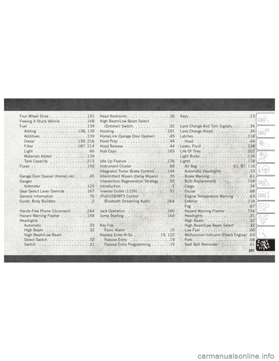
Four Wheel Drive..............131
Freeing A Stuck Vehicle ..........168
Fuel ......................139
Adding ...............138, 139
Additives .................139
Diesel ...............139, 216
Filter ................187, 214
Light ....................66
Materials Added ............139
Tank Capacity ..............213
Fuses .....................155
Garage Door Opener (HomeLink) ......45
Gauges Voltmeter ................125
Gear Select Lever Override ........167
General Information .............76
Guide, Body Builders .............2
Hands-Free Phone (Uconnect) ......264
Hazard Warning Flasher ..........154
Headlights Automatic .................33
High Beam ................32
High Beam/Low Beam
Select Switch ...............32
Switch ...................31 Head Restraints
................26
High Beam/Low Beam Select (Dimmer) Switch ..............32
Hoisting ....................191
HomeLink (Garage Door Opener) ......45
Hood Prop ...................44
Hood Release .................44
Hub Caps ...................163
Idle Up Feature ...............126
Instrument Cluster ..............68
Integrated Trailer Brake Controls .....144
Intermittent Wipers (Delay Wipers) ....35
Intervention Regeneration Strategy ....55
Introduction ...................1
Inverter Outlet (115V) ............51
iPod/USB/MP3 Control Bluetooth Streaming Audio ......264
Jack Operation ................160
Jump Starting ................164
Key
Fob
Panic Alarm ................15
Keyless Enter-N-Go ..........19, 122
Passive Entry ...............19
Passive Entry Programming .......19Keys
.......................13
Lane Change And Turn Signals .......34
Lane Change Assist ..............34
Latches ....................118
Hood ....................44
Leaks, Fluid .................118
Life Of Tires .................202
Light Bulbs ..................118
Lights .....................118
AirBag .............61, 87, 116
Automatic Headlights ..........33
Brake Warning ..............61
Bulb Replacement ...........154
Cargo ....................34
Cruise ...................68
Engine Temperature Warning .....63
Exterior ..................118
Fog .....................67
Hazard Warning Flasher ........154
Headlights .................31
High Beam ................32
High Beam/Low Beam Select .....32
Low Fuel ..................66
Malfunction Indicator (Check Engine) .63
Park ....................68
Seat Belt Reminder ...........61
291