display Ram 5500 Chassis Cab 2012 Repair Manual
[x] Cancel search | Manufacturer: RAM, Model Year: 2012, Model line: 5500 Chassis Cab, Model: Ram 5500 Chassis Cab 2012Pages: 508, PDF Size: 7.01 MB
Page 286 of 508
Key Ignition Park Interlock
This vehicle is equipped with a Key Ignition Park Inter-
lock which requires the shift lever to be placed in PARK
before the ignition switch can be turned to the LOCK/
OFF position. The key fob can only be removed from the
ignition when the ignition is in the LOCK/OFF position,
and once removed the shift lever is locked in PARK.
Brake/Transmission Shift Interlock System
This vehicle is equipped with a Brake Transmission Shift
Interlock System (BTSI) that holds the shift lever in the
PARK position unless the brakes are applied. To move
the shift lever out of the PARK position, the ignition
switch must be turned to the ON/RUN position (engine
running or not) and the brake pedal must be pressed.
Six–Speed Automatic Transmission
(5.7L Engine) — If Equipped
The shift lever position display (located in the instrument
panel cluster) indicates the transmission gear range. Theshift lever is mounted on the right side of the steering
column. You must press the brake pedal to move the shift
lever out of the PARK position (refer to “Brake/
Transmission Shift Interlock System” in this section). To
drive, move the shift lever from PARK or NEUTRAL to
the DRIVE position. Pull the shift lever toward you when
shifting into REVERSE or PARK, or when shifting out of
PARK.
The electronically-controlled transmission provides a
precise shift schedule. The transmission electronics are
self-calibrating; therefore, the first few shifts on a new
vehicle may be somewhat abrupt. This is a normal
condition, and precision shifts will develop within a few
hundred miles (kilometers).
Shifting from DRIVE to PARK or REVERSE should be
done only after the accelerator pedal is released and the
vehicle is stopped. Be sure to keep your foot on the brake
pedal when moving the shift lever between these gears.
284 STARTING AND OPERATING
Page 287 of 508

The transmission shift lever has only PARK, REVERSE,
NEUTRAL, and DRIVE shift positions. Manual down-
shifts can be made using the Electronic Range Select
(ERS) shift control (refer to “Electronic Range Select
(ERS)” in this section). Pressing the ERS (-/+) switches on
the shift lever while in the DRIVE position will select the
highest available transmission gear, and will display that
gear in the instrument cluster as 6, 5, 4, 3, 2, 1.
Gear Ranges
DO NOT race the engine when shifting from PARK or
NEUTRAL into another gear range.
PARK
This range supplements the parking brake by locking the
transmission. The engine can be started in this range.
Never attempt to use PARK while vehicle is in motion.
Apply the parking brake when leaving vehicle in this
range.When parking on a level surface, you may place the shift
lever in the PARK position first, and then apply the
parking brake.
When parking on a hill, apply the parking brake before
placing the shift lever in PARK, otherwise the load on the
transmission locking mechanism may make it difficult to
move the shift lever out of PARK. As an added precau-
tion, turn the front wheels toward the curb on a downhill
grade and away from the curb on an uphill grade
WARNING!
•Never use the PARK position as a substitute for
the parking brake. Always apply the parking
brake fully when parked to guard against vehicle
movement and possible injury or damage.
(Continued)
5
STARTING AND OPERATING 285
Page 289 of 508
CAUTION!
•Before moving the shift lever out of PARK, you
must turn the ignition switch from the LOCK/OFF
position to the ON/RUN position, and also press
the brake pedal. Otherwise, damage to the shift
lever could result.
•DO NOT race the engine when shifting from
PARK or NEUTRAL into another gear range, as
this can damage the drivetrain.
The following indicators should be used to ensure that
you have engaged the shift lever into the PARK position:
•When shifting into PARK, pull the shift lever toward
you and move it all the way counterclockwise until it
stops.
•Release the shift lever and make sure it is fully seated
in the PARK gate.
•Look at the shift lever position display and verify that
it indicates the PARK position.
•With brake pedal released, verify that the shift lever
will not move out of PARK.
REVERSE
This range is for moving the vehicle rearward. Use this
range only after the vehicle has come to a complete stop.
NEUTRAL
Use this range when the vehicle is standing for prolonged
periods with the engine running. The engine may be
started in this range. Set the parking brake and shift the
transmission into PARK if you must leave the vehicle.
5
STARTING AND OPERATING 287
Page 293 of 508
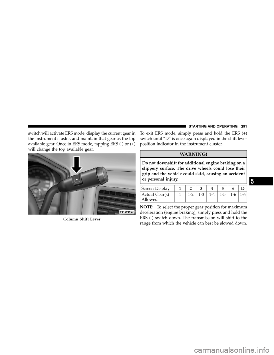
switch will activate ERS mode, display the current gear in
the instrument cluster, and maintain that gear as the top
available gear. Once in ERS mode, tapping ERS (-) or (+)
will change the top available gear.To exit ERS mode, simply press and hold the ERS (+)
switch until “D” is once again displayed in the shift lever
position indicator in the instrument cluster.
WARNING!
Do not downshift for additional engine braking on a
slippery surface. The drive wheels could lose their
grip and the vehicle could skid, causing an accident
or personal injury.
Screen Display123456D
Actual Gear(s)
Allowed1 1-2 1-3 1-4 1-5 1-6 1-6
NOTE:To select the proper gear position for maximum
deceleration (engine braking), simply press and hold the
ERS (-) switch down. The transmission will shift to the
range from which the vehicle can best be slowed down.
Column Shift Lever
5
STARTING AND OPERATING 291
Page 349 of 508

NOTE:Tighten the gas cap 1/4 turn until you hear one
click. This is an indication that the cap is properly
tightened.
If the gas cap is not tightened properly, the Malfunction
Indicator Light will come on, Be sure the gas cap is
tightened every time the vehicle is refueled.
WARNING!
A fire may result if gasoline is pumped into a
portable container that is inside of a vehicle. You
could be burned. Always place gas containers on the
ground while filling.
Loose Fuel Filler Cap Message
If the vehicle diagnostic system determines
that the fuel filler cap is loose, improperly
installed, or damaged, a loose gascap indicator
will display in the EVIC telltale display area.Refer to “Electronic Vehicle Information Center (EVIC) in
“Understanding Your Instrument Panel” for further in-
formation. Tighten the fuel filler cap properly and press
the SELECT button to turn off the message. If the
problem continues, the message will appear the next time
the vehicle is started.
VEHICLE LOADING
Certification Label
As required by National Highway Traffic Safety Admin-
istration regulations, your vehicle has a certification label
affixed to the driver’s side door or pillar.
This label contains the month and year of manufacture,
Gross Vehicle Weight Rating (GVWR), Gross Axle Weight
Rating (GAWR) front and rear, and Vehicle Identification
Number (VIN). A Month-Day-Hour (MDH) number is
included on this label and indicates the Month, Day and5
STARTING AND OPERATING 347
Page 361 of 508
The user interface consists of the following:
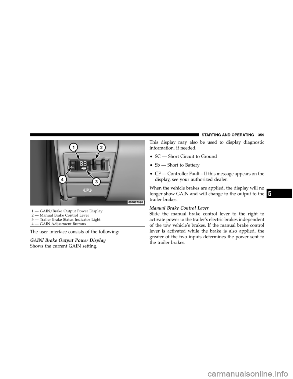
GAIN/ Brake Output Power Display
Shows the current GAIN setting.This display may also be used to display diagnostic
information, if needed.
•SC — Short Circuit to Ground
•Sb — Short to Battery
•CF — Controller Fault – If this message appears on the
display, see your authorized dealer.
When the vehicle brakes are applied, the display will no
longer show GAIN and will change to the output to the
trailer brakes.
Manual Brake Control Lever
Slide the manual brake control lever to the right to
activate power to the trailer’s electric brakes independent
of the tow vehicle’s brakes. If the manual brake control
lever is activated while the brake is also applied, the
greater of the two inputs determines the power sent to
the trailer brakes.
1 — GAIN/Brake Output Power Display
2 — Manual Brake Control Lever
3 — Trailer Brake Status Indicator Light
4 — GAIN Adjustment Buttons
5
STARTING AND OPERATING 359
Page 362 of 508
The trailer and the vehicle’s brake lamps will come on
when either vehicle braking or manual trailer brakes are
applied.
Trailer Brake Status Indicator Light
This light indicates the trailer electrical connection status.
If no electrical connection is detected after the ignition is
turned on, pressing the GAIN adjustment button or
sliding the manual brake control lever will display the
GAIN setting for 10 seconds and the “Trailer Brake Status
Indicator Light” will not be displayed.
If a fault is detected in the trailer wiring or the Integrated
Trailer Brake Module (ITBM), the “Trailer Brake Status
Indicator Light” will flash.
GAIN Adjustment Buttons (+/-)
Pressing these buttons will adjust the brake control
power output to the trailer brakes in 0.5 increments. TheGAIN setting can be increased to a maximum of 10 or
decreased to a minimum of 0 (no trailer braking).
GAIN
The GAIN setting is used to set the trailer brake control
for the specific towing condition and should be changed
as towing conditions change. Changes to towing condi-
tions include trailer load, vehicle load, road conditions
and weather.
Adjusting GAIN
NOTE:This should only be performed in a traffic free
environment at speeds of approximately 20–25 mph
(30–40 km/h).
1. Make sure the trailer brakes are in good working
condition, functioning normally, and properly adjusted.
See your trailer dealer if necessary.
2. Hook up the trailer and make the electrical connec-
tions according to the trailer manufacturer’s instructions.
360 STARTING AND OPERATING
Page 363 of 508
3. When a trailer with electric brakes is plugged in, the
GAIN setting will illuminate.
4. Use the GAIN adjustment (+/-) buttons to increase or
decrease the GAIN setting to the desired starting point. A
GAIN setting of 6 is a good starting point for heavier
loads.
5. In a traffic-free environment, tow the trailer on a dry,
level surface at a speed of 20–25 mph (30–40 km/h) and
squeeze the manual brake control lever completely.
6. If the trailer wheels lockup (indicated by squealing
tires), reduce the GAIN setting; if the trailer wheels turn
freely, increase the GAIN setting.
Repeat Steps 5 and 6 until the GAIN setting is at a point
just below trailer wheel lockup. If towing a heavier
trailer, trailer wheel lockup may not be attainable even
with the maximum GAIN setting of 10.EVIC Display Messages
The trailer brake control interacts with the Electronic
Vehicle Information Center (EVIC). Display messages,
along with a single chime, will be displayed when a
malfunction is determined in the trailer connection,
trailer brake control, or on the trailer. Refer to “Electronic
Vehicle Information Center (EVIC)” in “Understanding
Your Instrument Panel” for further information.
CAUTION!
The ITBM module has been designed and verified
for electric trailer brakes. Connecting a trailer that is
not compatible with the ITBM system may result in
reduced or complete loss of trailer braking. There
may be a increase in stopping distance or trailer
instability which could result in damage to your
vehicle, trailer, or other property.
5
STARTING AND OPERATING 361
Page 368 of 508

if necessary at the beginning and end of the snowplow
season. This will help prevent uneven tire wear.
The blade should be lowered whenever the vehicle is
parked.
Maintain and operate your vehicle and snowplow equip-
ment following the recommendations provided by the
specific snowplow manufacturer.
Over The Road Operation With Snowplow
Attached
The blade restricts air flow to the radiator and causes the
engine to operate at higher than normal temperatures.
Therefore, when transporting the plow, angle the blade
completely and position it as low as road or surface
conditions permit. Do not exceed 40 mph (64 km/h). The
operator should always maintain a safe stopping distance
and allow adequate passing clearance.
Operating Tips
Under ideal snow plowing conditions, 20 mph (32 km/h)
should be maximum operating speed. The operator
should be familiar with the area and surface to be
cleaned. Reduce speed and use extreme caution when
plowing unfamiliar areas or under poor visibility.
NOTE:During snowplow usage on vehicles equipped
with outside temperature display, the display may show
higher temperatures than the outside ambient tempera-
ture. The higher displayed temperature is due to blocked
or reduced airflow to the underhood ambient tempera-
ture sensor caused by the snowplow. In addition, on
vehicles equipped with Automatic Temperature Control
(ATC), it is suggested that the interior cabin temperature
be manually controlled should the system not perform as
desired while in automatic mode. Both the outside tem-
perature display and ATC operation will return to nor-
mal when the snowplow is removed.
366 STARTING AND OPERATING
Page 408 of 508

ONBOARD DIAGNOSTIC SYSTEM (OBD II)
Your vehicle is equipped with a sophisticated onboard
diagnostic system called OBD II. This system monitors
the performance of the emissions, engine, and automatic
transmission control systems. When these systems are
operating properly, your vehicle will provide excellent
performance and fuel economy, as well as engine emis-
sions well within current government regulations.
If any of these systems require service, the OBD II system
will turn on the “Malfunction Indicator Light (MIL).” It
will also store diagnostic codes and other information to
assist your service technician in making repairs. Al-
though your vehicle will usually be drivable and not
need towing, see your authorized dealer for service as
soon as possible.CAUTION!
•Prolonged driving with the MIL on could cause
further damage to the emission control system. It
could also affect fuel economy and drivability. The
vehicle must be serviced before any emissions
tests can be performed.
•If the MIL is flashing, while the engine is running,
severe catalytic converter damage and power loss
will soon occur. Immediate service is required.
Loose Fuel Filler Cap Message
If the vehicle diagnostic system determines
that the fuel filler cap is loose, improperly
installed, or damaged, a loose gascap indicator
will display in the EVIC telltale display area.
Refer to “Electronic Vehicle Information Center (EVIC) in
“Understanding Your Instrument Panel” for further in-
formation. Tighten the fuel filler cap properly and press
406 MAINTAINING YOUR VEHICLE