lights RAM CHASSIS CAB 2021 Owners Manual
[x] Cancel search | Manufacturer: RAM, Model Year: 2021, Model line: CHASSIS CAB, Model: RAM CHASSIS CAB 2021Pages: 463, PDF Size: 21.5 MB
Page 5 of 463
3
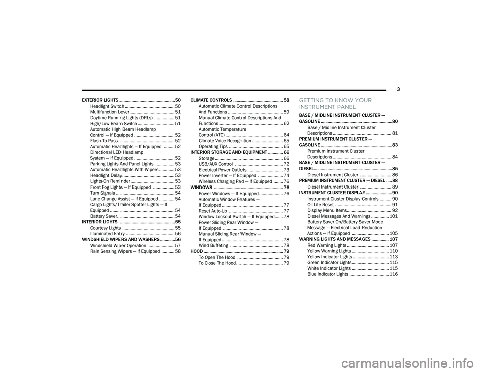
EXTERIOR LIGHTS.................................................50 Headlight Switch .......................................... 50
Multifunction Lever ...................................... 51
Daytime Running Lights (DRLs) ................. 51
High/Low Beam Switch ............................... 51
Automatic High Beam Headlamp
Control — If Equipped .................................. 52 Flash-To-Pass ............................................... 52
Automatic Headlights — If Equipped ......... 52
Directional LED Headlamp
System — If Equipped .................................. 52 Parking Lights And Panel Lights ................. 53
Automatic Headlights With Wipers ............. 53
Headlight Delay ............................................ 53
Lights-On Reminder ..................................... 53
Front Fog Lights — If Equipped .................. 53
Turn Signals ................................................. 54
Lane Change Assist — If Equipped ............. 54
Cargo Lights/Trailer Spotter Lights — If
Equipped ...................................................... 54 Battery Saver................................................ 54
INTERIOR LIGHTS ................................................55
Courtesy Lights ............................................ 55
Illuminated Entry ......................................... 56
WINDSHIELD WIPERS AND WASHERS .............56
Windshield Wiper Operation ...................... 57
Rain Sensing Wipers — If Equipped ........... 58 CLIMATE CONTROLS ........................................... 58
Automatic Climate Control Descriptions
And Functions .............................................. 59 Manual Climate Control Descriptions And
Functions...................................................... 62 Automatic Temperature
Control (ATC) ................................................ 64 Climate Voice Recognition .......................... 65
Operating Tips ............................................. 65
INTERIOR STORAGE AND EQUIPMENT ............. 66
Storage ......................................................... 66
USB/AUX Control ........................................ 72
Electrical Power Outlets .............................. 73
Power Inverter — If Equipped ..................... 74
Wireless Charging Pad — If Equipped ........ 76
WINDOWS ............................................................ 76
Power Windows — If Equipped .................... 76
Automatic Window Features —
If Equipped ................................................... 77 Reset Auto-Up ............................................. 77
Window Lockout Switch — If Equipped....... 78
Power Sliding Rear Window —
If Equipped .................................................. 78 Manual Sliding Rear Window —
If Equipped ................................................... 78 Wind Buffeting ............................................ 78
HOOD ..................................................................... 79
To Open The Hood ...................................... 79
To Close The Hood ....................................... 79
GETTING TO KNOW YOUR
INSTRUMENT PANEL
BASE / MIDLINE INSTRUMENT CLUSTER —
GASOLINE ..............................................................80
Base / Midline Instrument Cluster
Descriptions ................................................. 81
PREMIUM INSTRUMENT CLUSTER —
GASOLINE ..............................................................83
Premium Instrument Cluster
Descriptions ................................................. 84
BASE / MIDLINE INSTRUMENT CLUSTER —
DIESEL....................................................................85
Diesel Instrument Cluster .......................... 86
PREMIUM INSTRUMENT CLUSTER — DIESEL ..... 88
Diesel Instrument Cluster .......................... 89
INSTRUMENT CLUSTER DISPLAY .......................90
Instrument Cluster Display Controls .......... 90
Oil Life Reset ............................................... 91
Display Menu Items ..................................... 92
Diesel Messages And Warnings ............... 101 Battery Saver On/Battery Saver Mode
Message — Electrical Load Reduction
Actions — If Equipped ............................... 105
WARNING LIGHTS AND MESSAGES ............... 107
Red Warning Lights ................................... 107
Yellow Warning Lights ............................... 110Yellow Indicator Lights .............................. 113
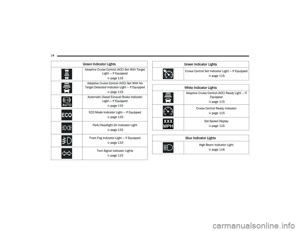
Green Indicator Lights ............................... 115White Indicator Lights ............................... 115Blue Indicator Lights ................................. 116
21_DPF_OM_EN_USC_t.book Page 3
Page 13 of 463
11
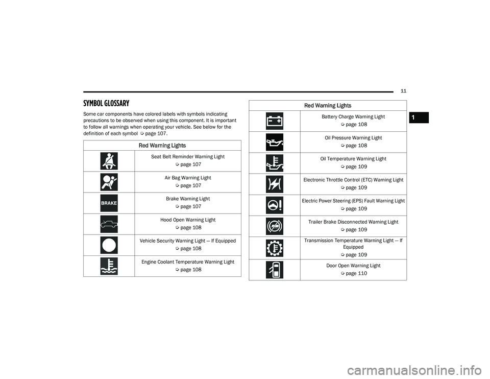
SYMBOL GLOSSARY
Some car components have colored labels with symbols indicating
precautions to be observed when using this component. It is important
to follow all warnings when operating your vehicle. See below for the
definition of each symbol Úpage 107.
Red Warning Lights
Seat Belt Reminder Warning Light
Úpage 107
Air Bag Warning Light Úpage 107
Brake Warning Light Úpage 107
Hood Open Warning Light Úpage 108
Vehicle Security Warning Light — If Equipped Úpage 108
Engine Coolant Temperature Warning Light Úpage 108
Battery Charge Warning Light
Úpage 108
Oil Pressure Warning Light Úpage 108
Oil Temperature Warning Light Úpage 109
Electronic Throttle Control (ETC) Warning Light Úpage 109
Electric Power Steering (EPS) Fault Warning Light
Úpage 109
Trailer Brake Disconnected Warning Light Úpage 109
Transmission Temperature Warning Light — If Equipped
Ú page 109
Door Open Warning Light Úpage 110
Red Warning Lights
1
21_DPF_OM_EN_USC_t.book Page 11
Page 14 of 463
12
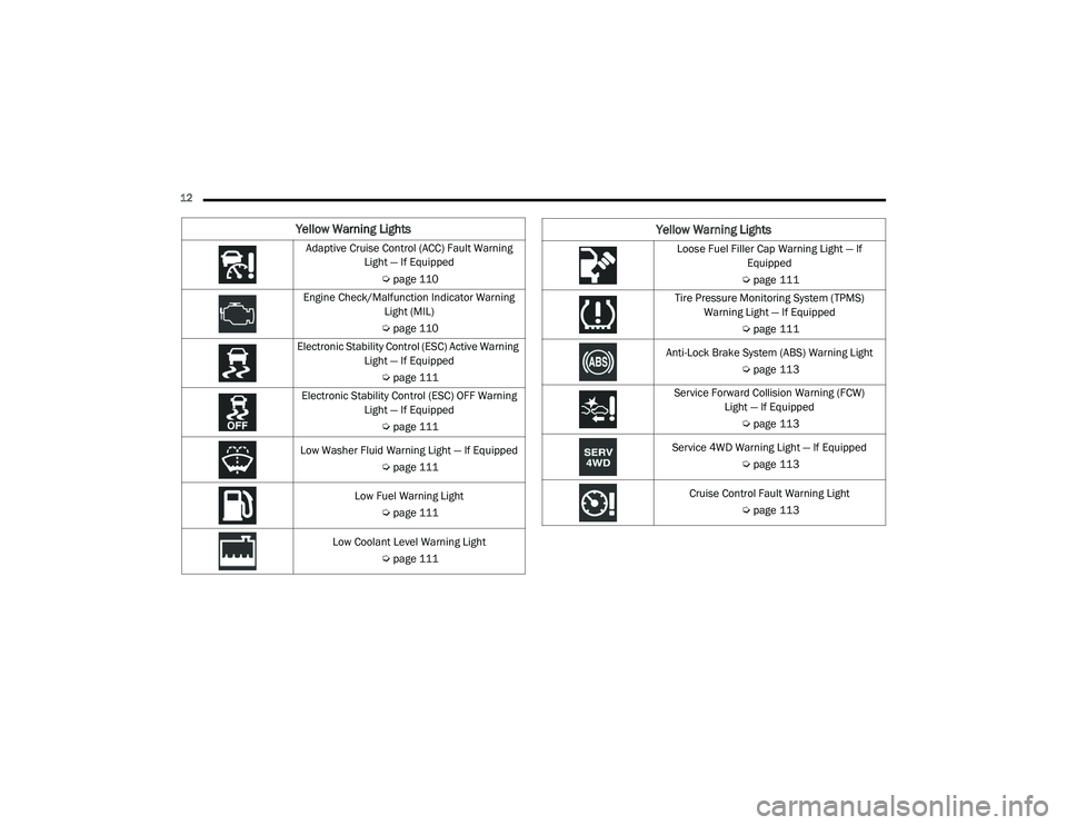
Yellow Warning Lights
Adaptive Cruise Control (ACC) Fault Warning Light — If Equipped
Úpage 110
Engine Check/Malfunction Indicator Warning Light (MIL)
Ú page 110
Electronic Stability Control (ESC) Active Warning Light — If Equipped
Úpage 111
Electronic Stability Control (ESC) OFF Warning Light — If Equipped
Úpage 111
Low Washer Fluid Warning Light — If Equipped Úpage 111
Low Fuel Warning Light Úpage 111
Low Coolant Level Warning Light Úpage 111Loose Fuel Filler Cap Warning Light — If
Equipped
Ú page 111
Tire Pressure Monitoring System (TPMS) Warning Light — If Equipped
Úpage 111
Anti-Lock Brake System (ABS) Warning Light Úpage 113
Service Forward Collision Warning (FCW) Light — If Equipped
Úpage 113
Service 4WD Warning Light — If Equipped Úpage 113
Cruise Control Fault Warning Light Úpage 113
Yellow Warning Lights
21_DPF_OM_EN_USC_t.book Page 12
Page 15 of 463
13
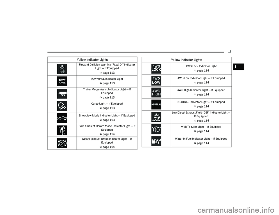
Yellow Indicator Lights
Forward Collision Warning (FCW) Off Indicator Light — If Equipped
Úpage 113
TOW/HAUL Indicator Light Úpage 113
Trailer Merge Assist Indicator Light — If Equipped
Ú page 113
Cargo Light — If Equipped Úpage 113
Snowplow Mode Indicator Light — If Equipped Úpage 113
Cold Ambient Derate Mode Indicator Light — If Equipped
Ú page 114
Diesel Exhaust Brake Indicator Light — If Equipped
Ú page 1144WD Lock Indicator Light
Úpage 114
4WD Low Indicator Light — If Equipped Úpage 114
4WD High Indicator Light — If Equipped Úpage 114
NEUTRAL Indicator Light — If Equipped Úpage 114
Low Diesel Exhaust Fluid (DEF) Indicator Light — If Equipped
Ú page 114
Wait To Start Light — If Equipped Úpage 114
Water In Fuel Indicator Light — If Equipped Úpage 114
Yellow Indicator Lights
1
21_DPF_OM_EN_USC_t.book Page 13
Page 16 of 463
14
Green Indicator Lights
Adaptive Cruise Control (ACC) Set With Target Light — If Equipped
Úpage 115
Adaptive Cruise Control (ACC) Set With No
Target Detected Indicator Light — If Equipped
Úpage 115
Automatic Diesel Exhaust Brake Indicator Light — If Equipped
Úpage 115
ECO Mode Indicator Light — If Equipped Úpage 115
Park/Headlight On Indicator Light Úpage 115
Front Fog Indicator Light — If Equipped Úpage 115
Turn Signal Indicator Lights Úpage 115Cruise Control Set Indicator Light — If Equipped
Úpage 115
White Indicator Lights
Adaptive Cruise Control (ACC) Ready Light — If
Equipped
Ú page 115
Cruise Control Ready Indicator Úpage 115
Set Speed Display Ú page 115
Blue Indicator Lights
High Beam Indicator Light
Úpage 116
Green Indicator Lights
21_DPF_OM_EN_USC_t.book Page 14
Page 22 of 463
20GETTING TO KNOW YOUR VEHICLE
(Continued)
REMOTE START — IF EQUIPPED
(GASOLINE)
This system uses the key fob to start
the engine conveniently from outside
the vehicle while still maintaining
security. The system has a range of
approximately 300 ft (91 m).
Remote start is used to defrost windows in cold
weather, and to reach a comfortable climate in
all ambient conditions before the driver enters
the vehicle.
NOTE:
Obstructions between the vehicle and the key
fob may reduce this range Ú page 449.
HOW TO USE REMOTE START
Push and release the Remote Start button on the
key fob twice within five seconds. The parking
lights will flash, vehicle doors will lock, and the
horn will chirp twice (if programmed). Once the
vehicle has started, the engine will run for
15 minutes.
Pushing the remote start button a third time
shuts the engine off.
To drive the vehicle, push the unlock button,
insert the key into the ignition, and turn to the
ON/RUN position. NOTE:
With Remote Start, the engine will only run
for 15 minutes.
Remote Start can only be used twice.
If an engine fault is present or fuel level is
low, the vehicle will start and then shut down
in 10 seconds.
The parking lights will turn on and remain on
during Remote Start mode.
For security, power window operation is
disabled when the vehicle is in the Remote
Start mode.
The ignition must be placed in the ON/RUN
position before the Remote Start sequence
can be repeated for a third cycle.
If your power door locks were unlocked,
Remote Start will automatically lock the
doors.
WARNING!
Do not start or run an engine in a closed
garage or confined area. Exhaust gas
contains Carbon Monoxide (CO) which is
odorless and colorless. Carbon Monoxide is
poisonous and can cause serious injury or
death when inhaled.
Keep key fobs away from children. Opera
-
tion of the Remote Start System, windows,
door locks or other controls could cause
serious injury or death.
WARNING! (Continued)
21_DPF_OM_EN_USC_t.book Page 20
Page 25 of 463
GETTING TO KNOW YOUR VEHICLE23
HOW TO USE REMOTE START
Push and release the Remote Start button on the
key fob twice within five seconds. The vehicle
doors will lock, the parking lights will flash, and
the horn will chirp twice (if programmed). Then,
the engine will start, and the vehicle will remain
in the Remote Start mode for a 15 minute cycle.
Pushing the remote start button a third time
shuts the engine off.
To drive the vehicle, push the unlock button,
insert the key into the ignition, and turn to the
ON/RUN position.
All of the following conditions must be met
before the engine will remote start:
Gear selector in PARK
Doors closed
Hood closed
Hazard switch off
Brake switch inactive (brake pedal not
pressed)
Battery at an acceptable charge level
PANIC button not pushed
Fuel meets minimum requirement
Water In Fuel Indicator Light is not illuminated
Wait To Start Light is not illuminated
Malfunction Indicator Light (MIL) is not illumi -
nated
For additional functions of the Remote Start
system, see Ú page 21
VEHICLE SECURITY SYSTEM — IF EQUIPPED
The Vehicle Security system monitors the
vehicle doors and ignition for unauthorized
operation. When the Vehicle Security system is
activated, interior switches for door locks are
disabled. If something triggers the alarm, the
Vehicle Security system will provide the
following audible and visible signals:
The horn will pulse
The turn signals will flash
The vehicle security light in the instrument
cluster will flash
TO ARM THE SYSTEM
Follow these steps to arm the Vehicle Security
system:
1. Make sure the vehicle’s ignition is placed
in the OFF position.
For vehicles equipped with Keyless Entry,
make sure the vehicle’s keyless ignition
system is OFF.
WARNING!
Do not start or run an engine in a closed
garage or confined area. Exhaust gas
contains Carbon Monoxide (CO) which is
odorless and colorless. Carbon Monoxide is
poisonous and can cause serious injury or
death when inhaled.
Keep key fobs away from children. Opera -
tion of the Remote Start System, windows,
door locks or other controls could cause
serious injury or death.
2
21_DPF_OM_EN_USC_t.book Page 23
Page 26 of 463
24GETTING TO KNOW YOUR VEHICLE
2. Perform one of the following methods to
lock the vehicle:
Push the lock button on the interior
power door lock switch with the driver
and/or passenger door open.
Push the lock button on the exterior
Passive Entry Door Handle with a valid
key fob available in the same exterior
zone Ú page 26.
Push the lock button on the key fob.
3. If any doors are open, close them.
The Vehicle Security system will set when you
use the power door locks, or use the key fob to
lock the doors. After all the doors are locked
and closed, the vehicle security light, in the
instrument panel cluster, will flash rapidly for
about 16 seconds to indicate that the alarm is
being set. After the alarm is set, the vehicle
security light will flash at a slower rate to
indicate that the system is armed.
TO DISARM THE SYSTEM
The Vehicle Security system can be disarmed
using any of the following methods:
1. Push the unlock button on the key fob.
2. Grab the Passive Entry Door Handle with a valid key fob within 5 ft (1.5 m) of the
Passive Entry door handle (if equipped)
Úpage 26.
3. Cycle the ignition out of the OFF position.
The Vehicle Security system is designed to
protect your vehicle. However, you can create
conditions where the system will give you a false
alarm. If one of the previously described arming
sequences has occurred, the Vehicle Security
system will arm regardless of whether you are in
the vehicle or not. If you remain in the vehicle
and open a door, the alarm will sound. If this
occurs, disarm the Vehicle Security system.
If the Vehicle Security system is armed and the
battery becomes disconnected, the Vehicle
Security system will remain armed when the
battery is reconnected; the exterior lights will
flash, and the horn will sound. If this occurs,
disarm the Vehicle Security system.
REARMING OF THE SYSTEM
If something triggers the alarm, and no action is
taken to disarm it, the Vehicle Security system
will turn the horn off after 29 seconds,
five seconds between cycles, and up to eight
cycles if the trigger remains active. The Vehicle
Security system will then rearm itself.
SECURITY SYSTEM MANUAL OVERRIDE
The Vehicle Security system will not arm if you
lock the doors using the manual door lock.
DOORS
MANUAL DOOR LOCKS
The power door locks can be manually locked
from inside the vehicle by using the door lock
knob. To lock each door, push the door lock
knob on each door trim panel downward.
To unlock the front doors, pull the inside door
handle to the first detent. To unlock the rear
doors, pull the door lock knob on the door trim
panel upward. If the lock knob is down when the
door is closed, the door will lock. Therefore,
make sure the key fob is not inside the vehicle
before closing the door.
21_DPF_OM_EN_USC_t.book Page 24
Page 39 of 463

GETTING TO KNOW YOUR VEHICLE37
Front Heated Seats
The heated seats control buttons are located on
the center instrument panel below the
touchscreen, and are also located within the
climate or controls screen of the touchscreen.
Push the heated seat button once to turn
the HI setting on.
Push the heated seat button a second
time to turn the MED setting on.
Push the heated seat button a third time
to turn the LO setting on.
Push the heated seat button a fourth time
to turn the heating elements off. NOTE:
The engine must be running for the heated
seats to operate.
The level of heat selected will stay on until
the operator changes it.
For information on use with the Remote Start
system, see Ú page 21.
Rear Heated Seats
On some models, the two outboard rear seats
are equipped with heated seats. The heated
seat switches for these seats are located on the
rear of the center console.
There are two heated seat switches that allow
the rear passengers to operate the seats
independently. You can choose from HI, MED,
LO, or OFF heat settings. Amber indicator lights
in each switch indicate the level of heat in use.
Push the heated seat button once to turn
the HI setting on.
Push the heated seat button a second
time to turn the MED setting on.
Push the heated seat button a third time
to turn the LO setting on.
Push the heated seat button a fourth time
to turn the heating elements off.
NOTE:
The level of heat selected will stay on until
the operator changes it.
Once a heat setting is selected, heat will be
felt within two to five minutes.
The engine must be running for the heated
seats to operate.
VENTILATED SEATS — IF EQUIPPED
Front Ventilated Seats
Located in the seat cushion are small fans that
draw the air from the passenger compartment
and move air through fine perforations in the seat
cover to help keep the driver and front passenger
cooler in higher ambient temperatures. The fans
operate at three speeds, HI, MED and LO.
Do not place anything on the seat or seat -
back that insulates against heat, such as a
blanket or cushion. This may cause the seat
heater to overheat. Sitting in a seat that has
been overheated could cause serious
burns due to the increased surface
temperature of the seat.
WARNING! (Continued)
2
21_DPF_OM_EN_USC_t.book Page 37
Page 45 of 463
GETTING TO KNOW YOUR VEHICLE43
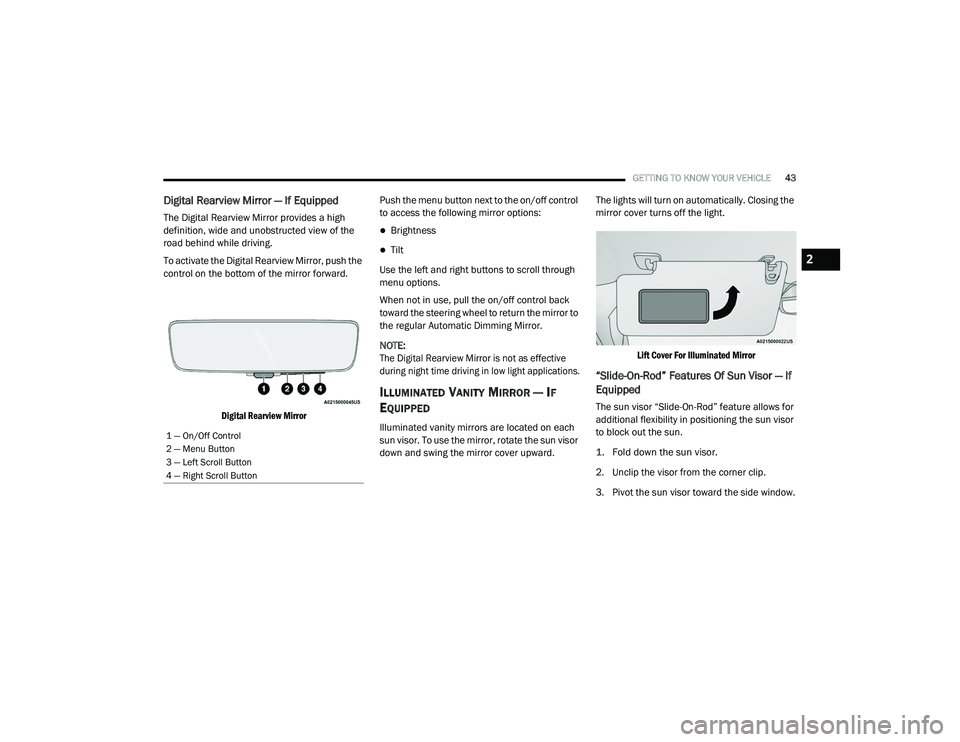
Digital Rearview Mirror — If Equipped
The Digital Rearview Mirror provides a high
definition, wide and unobstructed view of the
road behind while driving.
To activate the Digital Rearview Mirror, push the
control on the bottom of the mirror forward.
Digital Rearview Mirror
Push the menu button next to the on/off control
to access the following mirror options:
Brightness
Tilt
Use the left and right buttons to scroll through
menu options.
When not in use, pull the on/off control back
toward the steering wheel to return the mirror to
the regular Automatic Dimming Mirror.
NOTE:
The Digital Rearview Mirror is not as effective
during night time driving in low light applications.
ILLUMINATED VANITY MIRROR — IF
E
QUIPPED
Illuminated vanity mirrors are located on each
sun visor. To use the mirror, rotate the sun visor
down and swing the mirror cover upward. The lights will turn on automatically. Closing the
mirror cover turns off the light.
Lift Cover For Illuminated Mirror
“Slide-On-Rod” Features Of Sun Visor — If
Equipped
The sun visor “Slide-On-Rod” feature allows for
additional flexibility in positioning the sun visor
to block out the sun.
1. Fold down the sun visor.
2. Unclip the visor from the corner clip.
3. Pivot the sun visor toward the side window.
1 — On/Off Control
2 — Menu Button
3 — Left Scroll Button
4 — Right Scroll Button
2
21_DPF_OM_EN_USC_t.book Page 43