open hood RAM CHASSIS CAB 2021 Owners Manual
[x] Cancel search | Manufacturer: RAM, Model Year: 2021, Model line: CHASSIS CAB, Model: RAM CHASSIS CAB 2021Pages: 463, PDF Size: 21.5 MB
Page 5 of 463

3
EXTERIOR LIGHTS.................................................50 Headlight Switch .......................................... 50
Multifunction Lever ...................................... 51
Daytime Running Lights (DRLs) ................. 51
High/Low Beam Switch ............................... 51
Automatic High Beam Headlamp
Control — If Equipped .................................. 52 Flash-To-Pass ............................................... 52
Automatic Headlights — If Equipped ......... 52
Directional LED Headlamp
System — If Equipped .................................. 52 Parking Lights And Panel Lights ................. 53
Automatic Headlights With Wipers ............. 53
Headlight Delay ............................................ 53
Lights-On Reminder ..................................... 53
Front Fog Lights — If Equipped .................. 53
Turn Signals ................................................. 54
Lane Change Assist — If Equipped ............. 54
Cargo Lights/Trailer Spotter Lights — If
Equipped ...................................................... 54 Battery Saver................................................ 54
INTERIOR LIGHTS ................................................55
Courtesy Lights ............................................ 55
Illuminated Entry ......................................... 56
WINDSHIELD WIPERS AND WASHERS .............56
Windshield Wiper Operation ...................... 57
Rain Sensing Wipers — If Equipped ........... 58 CLIMATE CONTROLS ........................................... 58
Automatic Climate Control Descriptions
And Functions .............................................. 59 Manual Climate Control Descriptions And
Functions...................................................... 62 Automatic Temperature
Control (ATC) ................................................ 64 Climate Voice Recognition .......................... 65
Operating Tips ............................................. 65
INTERIOR STORAGE AND EQUIPMENT ............. 66
Storage ......................................................... 66
USB/AUX Control ........................................ 72
Electrical Power Outlets .............................. 73
Power Inverter — If Equipped ..................... 74
Wireless Charging Pad — If Equipped ........ 76
WINDOWS ............................................................ 76
Power Windows — If Equipped .................... 76
Automatic Window Features —
If Equipped ................................................... 77 Reset Auto-Up ............................................. 77
Window Lockout Switch — If Equipped....... 78
Power Sliding Rear Window —
If Equipped .................................................. 78 Manual Sliding Rear Window —
If Equipped ................................................... 78 Wind Buffeting ............................................ 78
HOOD ..................................................................... 79
To Open The Hood ...................................... 79
To Close The Hood ....................................... 79
GETTING TO KNOW YOUR
INSTRUMENT PANEL
BASE / MIDLINE INSTRUMENT CLUSTER —
GASOLINE ..............................................................80
Base / Midline Instrument Cluster
Descriptions ................................................. 81
PREMIUM INSTRUMENT CLUSTER —
GASOLINE ..............................................................83
Premium Instrument Cluster
Descriptions ................................................. 84
BASE / MIDLINE INSTRUMENT CLUSTER —
DIESEL....................................................................85
Diesel Instrument Cluster .......................... 86
PREMIUM INSTRUMENT CLUSTER — DIESEL ..... 88
Diesel Instrument Cluster .......................... 89
INSTRUMENT CLUSTER DISPLAY .......................90
Instrument Cluster Display Controls .......... 90
Oil Life Reset ............................................... 91
Display Menu Items ..................................... 92
Diesel Messages And Warnings ............... 101 Battery Saver On/Battery Saver Mode
Message — Electrical Load Reduction
Actions — If Equipped ............................... 105
WARNING LIGHTS AND MESSAGES ............... 107
Red Warning Lights ................................... 107
Yellow Warning Lights ............................... 110Yellow Indicator Lights .............................. 113
Green Indicator Lights ............................... 115White Indicator Lights ............................... 115Blue Indicator Lights ................................. 116
21_DPF_OM_EN_USC_t.book Page 3
Page 13 of 463

11
SYMBOL GLOSSARY
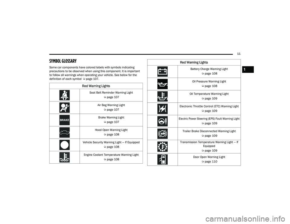
Some car components have colored labels with symbols indicating
precautions to be observed when using this component. It is important
to follow all warnings when operating your vehicle. See below for the
definition of each symbol Úpage 107.
Red Warning Lights
Seat Belt Reminder Warning Light
Úpage 107
Air Bag Warning Light Úpage 107
Brake Warning Light Úpage 107
Hood Open Warning Light Úpage 108
Vehicle Security Warning Light — If Equipped Úpage 108
Engine Coolant Temperature Warning Light Úpage 108
Battery Charge Warning Light
Úpage 108
Oil Pressure Warning Light Úpage 108
Oil Temperature Warning Light Úpage 109
Electronic Throttle Control (ETC) Warning Light Úpage 109
Electric Power Steering (EPS) Fault Warning Light
Úpage 109
Trailer Brake Disconnected Warning Light Úpage 109
Transmission Temperature Warning Light — If Equipped
Ú page 109
Door Open Warning Light Úpage 110
Red Warning Lights
1
21_DPF_OM_EN_USC_t.book Page 11
Page 24 of 463

22GETTING TO KNOW YOUR VEHICLE
Automatic Temperature Control (ATC) — If
Equipped
The climate controls automatically adjust to an
optimal temperature and mode, dependent on
the outside ambient temperature. When the
ignition is placed in the ON/RUN position, the
climate controls will resume their previous
settings.
Manual Temperature Control (MTC) — If
Equipped
In ambient temperatures of 40°F (4.5°C) or
below, the climate settings will default to
maximum heat, with fresh air entering the
cabin. If the front defrost timer expires, the
vehicle will enter Mix Mode.
In ambient temperatures from 40°F (4.5°C)
to 78°F (26°C), the climate settings will be
based on the last settings selected by the
driver.
In ambient temperatures of 78°F (26°C) or
above, the climate settings will default to MAX
A/C, Bi-Level mode, with Recirculation on.
For more information on ATC, MTC, and climate
control settings, see Ú page 58. NOTE:
These features will stay on through the duration
of remote start, or until the ignition is placed in
the ON/RUN position. The climate control
settings will change, and exit the automatic
defaults, if manually adjusted by the driver
while the vehicle is in remote start mode.
This includes turning the climate controls off
using the OFF button.
REMOTE START ABORT MESSAGE
The following messages will display in the
instrument cluster display if the vehicle fails to
remote start or exits remote start prematurely:
Remote Start Cancelled — Door Open
Remote Start Cancelled — Hood Open
Remote Start Cancelled — Fuel Low
Remote Start Cancelled — System Fault
Remote Start Disabled — Start Vehicle to Reset
The instrument cluster display message stays
active until the ignition is placed in the ON/RUN
position.
REMOTE START — IF EQUIPPED (DIESEL)
This system uses the key fob to start
the engine conveniently from outside
the vehicle while still maintaining
security. The system has a range of
approximately 300 ft (91 m).
Remote start is used to defrost windows in cold
weather, and to reach a comfortable climate in
all ambient conditions before the driver enters
the vehicle.
NOTE:
Obstructions between the vehicle and the
key fob may reduce this range.
The Remote Start system will wait for the
Wait To Start Light Úpage 114 to extinguish
before cranking the engine. This allows time
for the intake heater to preheat the incoming
air, and is normal operation in cold weather.
21_DPF_OM_EN_USC_t.book Page 22
Page 81 of 463

GETTING TO KNOW YOUR VEHICLE79
HOOD
TO OPEN THE HOOD
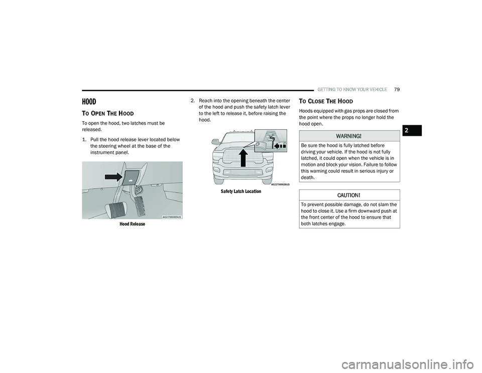
To open the hood, two latches must be
released.
1. Pull the hood release lever located below
the steering wheel at the base of the
instrument panel.
Hood Release
2. Reach into the opening beneath the center
of the hood and push the safety latch lever
to the left to release it, before raising the
hood.
Safety Latch Location
TO CLOSE THE HOOD
Hoods equipped with gas props are closed from
the point where the props no longer hold the
hood open.
WARNING!
Be sure the hood is fully latched before
driving your vehicle. If the hood is not fully
latched, it could open when the vehicle is in
motion and block your vision. Failure to follow
this warning could result in serious injury or
death.
CAUTION!
To prevent possible damage, do not slam the
hood to close it. Use a firm downward push at
the front center of the hood to ensure that
both latches engage.
2
21_DPF_OM_EN_USC_t.book Page 79
Page 110 of 463

108GETTING TO KNOW YOUR INSTRUMENT PANEL
Vehicles equipped with the Anti-Lock Brake
System (ABS) are also equipped with Electronic
Brake Force Distribution (EBD). In the event of
an EBD failure, the Brake Warning Light will turn
on along with the ABS Light. Immediate repair to
the ABS system is required.
Operation of the Brake Warning Light can be
checked by turning the ignition switch from the
OFF position to the ON/RUN position. The light
should illuminate for approximately two seconds.
The light should then turn off unless the parking
brake is applied or a brake fault is detected. If the
light does not illuminate, have the light inspected
by an authorized dealer.
The light also will turn on when the parking
brake is applied with the ignition switch in the
ON/RUN position. NOTE:
This light shows only that the parking brake is
applied. It does not show the degree of brake
application.
Hood Open Warning Light
This warning light will illuminate when
the hood is ajar/open and not fully
closed.
NOTE:
If the vehicle is moving, there will also be a
single chime.
Vehicle Security Warning Light — If
Equipped
This light will flash at a fast rate for
approximately 15 seconds when the
vehicle security alarm is arming, and
then will flash slowly until the vehicle
is disarmed.
Engine Coolant Temperature Warning
Light
This warning light warns of an
overheated engine condition. If the
engine coolant temperature is too
high, this indicator will illuminate and
a single chime will sound. If the temperature reaches the upper limit, a continuous chime will
sound for four minutes or until the engine is
able to cool, whichever comes first.
If the light turns on while driving, safely pull over
and stop the vehicle. If the Air Conditioning
(A/C) system is on, turn it off. Also, shift the
transmission into NEUTRAL and idle the vehicle.
If the temperature reading does not return to
normal, turn the engine off immediately and call
for service Ú
page 346.
Battery Charge Warning Light
This warning light will illuminate when
the battery is not charging properly.
If it stays on while the engine is
running, there may be a malfunction
with the charging system. Contact an
authorized dealer as soon as possible.
This indicates a possible problem with the
electrical system or a related component.
Oil Pressure Warning Light
This warning light will illuminate to
indicate low engine oil pressure. If the
light turns on while driving, stop the
vehicle, shut off the engine as soon as
possible, and contact an authorized dealer.
A chime will sound when this light turns on.
WARNING!
Driving a vehicle with the red brake light on is
dangerous. Part of the brake system may
have failed. It will take longer to stop the
vehicle. You could have a collision. Have the
vehicle checked immediately.
21_DPF_OM_EN_USC_t.book Page 108
Page 138 of 463

136STARTING AND OPERATING
The engine block heater must be plugged in at
least one hour to have an adequate warming
effect on the engine.
Diesel Engine Only
The engine block heater warms engine coolant
and permits quicker starts in cold weather.
Connect the heater cord to a ground-fault
interrupter protected 110–115 Volt AC
electrical outlet with a grounded, three-wire
extension cord.
The engine block heater cord is routed under
the hood to the right side and can be located
just behind the grille near the headlamp.
NOTE:
The engine block heater cord is a factory
installed option. If your vehicle is not equipped,
heater cords are available from an authorized
Mopar dealer. The block heater must be plugged in at least
one hour to have an adequate warming effect
on the coolant.
NOTE:
The block heater will require 110 Volts AC and
6.5 Amps to activate the heater element.
Block Heater Usage
For ambient temperatures below 0°F (-18°C),
engine block heater usage is recommended.
For ambient temperatures below –20°F
(-29°C), engine block heater usage is required.ENGINE BREAK-IN RECOMMENDATIONS —
GASOLINE ENGINE
A long break-in period is not required for the
engine and drivetrain (transmission and axle) in
your vehicle.
Drive moderately during the first 300 miles
(500 km). After the initial 60 miles (100 km),
speeds up to 50 or 55 mph (80 or 90 km/h) are
desirable.
While cruising, brief full-throttle acceleration
within the limits of local traffic laws contributes
to a good break-in. Wide-open throttle
acceleration in low gear can be detrimental and
should be avoided.
The engine oil installed in the engine at the
factory is a high-quality energy conserving type
lubricant. Oil changes should be consistent
with anticipated climate conditions under
which vehicle operations will occur. For the
recommended viscosity and quality grades
Ú
page 440.WARNING!
Remember to disconnect the engine block
heater cord before driving. Damage to the
110-115 Volt electrical cord could cause
electrocution.
WARNING!
Remember to disconnect the engine block
heater cord before driving. Damage to the
110-115 Volt electrical cord could cause
electrocution.
21_DPF_OM_EN_USC_t.book Page 136
Page 347 of 463

IN CASE OF EMERGENCY345
3. If using another vehicle to jump start the
battery, park the vehicle within the jumper
cables reach, apply the parking brake, and
make sure the ignition is OFF.JUMP STARTING PROCEDURE
NOTE:
Make sure at all times that unused ends of
jumper cables are not contacting each other or
either vehicle while making connections.
Connecting The Jumper Cables
1. Connect the positive
(+) end of the jumper
cable to the positive (+)
post of the
discharged vehicle.
NOTE:
Do not jump off fuses. Only jump directly off
positive post. 2. Connect the opposite end of the positive
(+)
jumper cable to the positive (+) post of the
booster battery.
3. Connect the negative (-) end of the jumper
cable to the negative (-) post of the booster
battery.
4. Connect the opposite end of the negative (-)
jumper cable to a good engine ground.
A “ground” is an exposed metallic/
unpainted part of the engine, frame or
chassis, such as an accessory bracket or
large bolt. The ground must be away from
the battery and fuel injection system.
5. Start the engine in the vehicle that has the booster battery, let the engine idle a few
minutes, and then start the engine in the
vehicle with the discharged battery.
WARNING!
Take care to avoid the radiator cooling fan
whenever the hood is raised. It can start
anytime the ignition switch is ON. You can
be injured by moving fan blades.
Remove any metal jewelry such as rings,
watch bands and bracelets that could
make an inadvertent electrical contact.
You could be seriously injured.
Batteries contain sulfuric acid that can
burn your skin or eyes and generate
hydrogen gas which is flammable and
explosive. Keep open flames or sparks
away from the battery.
WARNING!
Do not allow vehicles to touch each other as
this could establish a ground connection and
personal injury could result.
WARNING!
Failure to follow this jump starting procedure
could result in personal injury or property
damage due to battery explosion.
CAUTION!
Failure to follow these procedures could
result in damage to the charging system of
the booster vehicle or the discharged vehicle.
WARNING!
Do not connect the jumper cable to the
negative (-) post of the discharged battery.
The resulting electrical spark could cause the
battery to explode and could result in
personal injury.7
21_DPF_OM_EN_USC_t.book Page 345
Page 348 of 463

346IN CASE OF EMERGENCY
6. Once the engine is started, follow the
disconnecting procedure below.
Disconnecting The Jumper Cables
1. Disconnect the negative
(-)
end of the
jumper cable from the engine ground of
the vehicle with the discharged battery.
2. Disconnect the opposite end of the negative (-) jumper cable from the
negative (-) post of the booster battery.
3. Disconnect the positive (+) end of the
jumper cable from the positive (+) post of
the booster battery.
4. Disconnect the opposite end of the positive (+) jumper cable from the
positive (+) post of the vehicle with the
discharged battery.
If frequent jump starting is required to start your
vehicle you should have the battery and charging
system inspected at an authorized dealer.
IF YOUR ENGINE OVERHEATS
In any of the following situations, you can
reduce the potential for overheating by taking
the appropriate action.
On the highways — slow down.
In city traffic — while stopped, place the trans
-
mission in NEUTRAL, but do not increase the
engine idle speed while preventing vehicle
motion with the brakes. NOTE:
There are steps that you can take to slow down
an impending overheat condition:
If your Air Conditioner (A/C) is on, turn it off.
The A/C system adds heat to the engine
cooling system and turning the A/C off can
help remove this heat.
You can also turn the temperature control to
maximum heat, the mode control to floor and
the blower control to high. This allows the
heater core to act as a supplement to the
radiator and aids in removing heat from the
engine cooling system.
CAUTION!
Do not connect jumper cable to any of the
fuses on the positive battery terminal. The
resulting electrical current will blow the fuse.
CAUTION!
Accessories plugged into the vehicle power
outlets draw power from the vehicle’s battery,
even when not in use (i.e., cellular devices,
etc.). Eventually, if plugged in long enough
without engine operation, the vehicle’s battery
will discharge sufficiently to degrade battery
life and/or prevent the engine from starting.
WARNING!
You or others can be badly burned by hot
engine coolant (antifreeze) or steam from
your radiator. If you see or hear steam coming
from under the hood, do not open the hood
until the radiator has had time to cool. Never
try to open a cooling system pressure cap
when the radiator or coolant bottle is hot.
21_DPF_OM_EN_USC_t.book Page 346
Page 377 of 463

SERVICING AND MAINTENANCE375
Some conditions can be caused by a faulty
component such as a belt pulley. Belt pulleys
should be carefully inspected for damage and
proper alignment.
Belt replacement on some models requires the
use of special tools, we recommend having your
vehicle serviced at an authorized dealer.
DRAINING FUEL/WATER SEPARATOR
F
ILTER
There are two fuel filter assemblies. One is
located on the driver's side of the engine.
The best access to this water drain valve is from
under the hood. The second one is on the under
body, located in front of the rear axle above the
drive shaft on pick-up models. The Chassis Cab
models second filter location is on the frame
behind the front axle. The best access to this
water drain valve is from under the vehicle. If water is detected in the water separator while
the engine is running, or while the ignition
switch is in the ON position, the “Water In Fuel
Indicator Light” will illuminate and an audible
chime will be heard five times. At this point you
should stop the engine and drain the water from
both of the filters.
If the “Water In Fuel Indicator Light” comes on
and a single chime is heard while you are
driving, or with the ignition switch in the ON
position, there may be a problem with your
water separator wiring or sensor. See an
authorized dealer for service.
Upon proper draining of the water from both
fuel filters, the “Water In Fuel Indicator Light”
will remain illuminated for approximately
10 seconds. If the water was drained while
the engine was running, the “Water In Fuel
Indicator Light” may remain on for
approximately three minutes.NOTE:
Care should be taken in disposing of used fluids
from your vehicle. Used fluids, indiscriminately
discarded, can present a problem to the envi
-
ronment. Contact an authorized dealer, service
station, or government agency for advice on
recycling programs and for where used fluids
and filters can be properly disposed of in your
area.
Drain the fuel/water separator filters when the
“Water In Fuel Indicator Light” is ON. Within
10 minutes of vehicle shutdown, turn the engine
mounted filter drain valve (located on the side of
the filter assembly) counterclockwise a quarter
turn, and turn the under body mounted filter
drain valve (located on the bottom of the filter
assembly) counterclockwise 1 full turn. Then turn
the ignition switch to the ON position, and allow
any accumulated water to drain. Leave the drain
valve open until all water and contaminants have
been removed. When clean fuel is visible, close
the drain valve following these guidelines:
1. Rotate the drain clockwise to close until you feel resistance from the internal seal.
2. Continue turning the drain half of a turn to properly compress the seal.
CAUTION!
Do not drain the fuel/water separator filter
when the engine is running.
Diesel fuel will damage blacktop paving
surfaces. Drain the filter into an appro-
priate container.
CAUTION!
If the “Water In Fuel Indicator Light” remains
on, DO NOT START the engine before you
drain water from the fuel filters to avoid
engine damage.
8
21_DPF_OM_EN_USC_t.book Page 375
Page 385 of 463

SERVICING AND MAINTENANCE383
Under normal operating conditions, the catalytic
converter will not require maintenance. However,
it is important to keep the engine properly tuned
to ensure proper catalyst operation and prevent
possible catalyst damage.
NOTE:
Intentional tampering with emissions control
systems can result in civil penalties being
assessed against you.
In unusual situations involving grossly
malfunctioning engine operation, a scorching
odor may suggest severe and abnormal catalyst
overheating. If this occurs, stop the vehicle, turn off
the engine and allow it to cool. Service, including a
tune-up to manufacturer's specifications, should be
obtained immediately.
To minimize the possibility of catalytic converter
damage:
Do not interrupt the ignition when the trans
-
mission is in gear and the vehicle is in
motion.
Do not try to start the vehicle by pushing or
towing the vehicle.
Do not idle the engine with any ignition
components disconnected or removed, such
as when diagnostic testing, or for prolonged
periods during very rough idle or malfunc -
tioning operating conditions.
COOLING SYSTEM CAUTION!
The catalytic converter requires the use of
unleaded fuel only. Leaded gasoline will
destroy the effectiveness of the catalyst as
an emissions control device and may seri -
ously reduce engine performance and
cause serious damage to the engine.
Damage to the catalytic converter can result
if your vehicle is not kept in proper operating
condition. In the event of engine malfunc -
tion, particularly involving engine misfire or
other apparent loss of performance, have
your vehicle serviced promptly. Continued
operation of your vehicle with a severe
malfunction could cause the converter to
overheat, resulting in possible damage to
the converter and vehicle.
WARNING!
You or others can be badly burned by hot
engine coolant (antifreeze) or steam from your
radiator. If you see or hear steam coming from
under the hood, do not open the hood until the
radiator has had time to cool. Never open a
cooling system pressure cap when the radiator
or coolant bottle is hot.
Keep hands, tools, clothing, and jewelry
away from the radiator cooling fan when
the hood is raised. The fan starts automati -
cally and may start at any time, whether the
engine is running or not.
When working near the radiator cooling fan,
disconnect the fan motor lead or turn the
ignition to the OFF mode. The fan is
temperature controlled and can start at any
time the ignition is in the ON mode.
8
21_DPF_OM_EN_USC_t.book Page 383