rear view mirror RAM CHASSIS CAB 2021 Owners Manual
[x] Cancel search | Manufacturer: RAM, Model Year: 2021, Model line: CHASSIS CAB, Model: RAM CHASSIS CAB 2021Pages: 463, PDF Size: 21.5 MB
Page 4 of 463
2
INTRODUCTION
Symbols Key ..........................................................10
VAN CONVERSIONS/CAMPERS ..........................10
VEHICLE MODIFICATIONS/ALTERATIONS .........10
Symbol Glossary ...................................................11
GETTING TO KNOW YOUR VEHICLE
KEYS ......................................................................15
Key Fob......................................................... 15
SENTRY KEY ..........................................................17
IGNITION SWITCH .................................................18
Keyless Push Button Ignition ...................... 18
REMOTE START — IF EQUIPPED (GASOLINE) ..20
How To Use Remote Start ........................... 20
To Exit Remote Start Mode ......................... 21
Remote Start Front Defrost
Activation — If Equipped .............................. 21 Remote Start Comfort Systems —
If Equipped ................................................... 21 Remote Start Abort Message ...................... 22
REMOTE START — IF EQUIPPED (DIESEL) .........22
How To Use Remote Start ........................... 23
VEHICLE SECURITY SYSTEM — IF EQUIPPED ...23
To Arm The System ...................................... 23
To Disarm The System................................. 24
Rearming Of The System............................. 24
Security System Manual Override .............. 24 DOORS .................................................................. 24
Manual Door Locks...................................... 24
Power Door Locks — If Equipped ............... 25
Keyless Enter-N-Go — Passive Entry
(If Equipped) ................................................ 26 Automatic Unlock Doors On
Exit — If Equipped ........................................ 28 Automatic Door Locks — If Equipped ......... 28
Child-Protection Door Lock — If Equipped.. 28
STEERING WHEEL ............................................... 29
Tilt Steering Column .................................... 29
Heated Steering Wheel — If Equipped ....... 29
UCONNECT VOICE RECOGNITION ....................... 30
Introducing Voice Recognition .................... 30
Basic Voice Commands............................... 31
Get Started ................................................... 31
Additional Information ................................. 31
DRIVER MEMORY SETTINGS — IF EQUIPPED ... 32
Programming The Memory Feature............ 32
Linking And Unlinking The Remote
Keyless Entry Key Fob To Memory ............. 32 Memory Position Recall............................... 33
SEATS .................................................................... 33
Manual Front Seat Adjustment................... 34
Power Driver Seat Adjustment —
If Equipped ................................................... 35 Heated Seats — If Equipped ....................... 36
Ventilated Seats — If Equipped................... 37
Head Restraints ........................................... 38 DRIVER ADJUSTABLE PEDALS —
IF EQUIPPED .........................................................40
MIRRORS ..............................................................41
Inside Rearview Mirror ................................ 41
Illuminated Vanity Mirror — If Equipped ..... 43
Outside Mirrors ........................................... 44
Driver's Outside Automatic Dimming
Mirror — If Equipped .................................... 44 Power Mirrors — If Equipped ...................... 44
Power Convex Mirror Switch —
If Equipped ................................................... 45 Trailer Towing Mirrors.................................. 46
Heated Mirrors — If Equipped ..................... 46
Tilt Side Mirrors In Reverse — If Equipped ... 46
Outside Mirrors Folding Feature ................. 46
UNIVERSAL GARAGE DOOR OPENER
(HOMELINK®) — IF EQUIPPED ...........................47
Before You Begin Programming
HomeLink® .................................................. 47 Erasing All The HomeLink® Channels ....... 47
Identifying Whether You Have A Rolling
Code Or Non-Rolling Code Device .............. 47 Programming HomeLink® To A Garage
Door Opener................................................. 48 Programming HomeLink® To A
Miscellaneous Device ................................. 49 Reprogramming A Single HomeLink®
Button ........................................................... 49 Canadian/Gate Operator Programming..... 50
21_DPF_OM_EN_USC_t.book Page 2
Page 43 of 463
GETTING TO KNOW YOUR VEHICLE41
The pedals cannot be adjusted when the vehicle is
in REVERSE or when the Cruise Control system is on.
If there is an attempt to adjust the pedals when the
system is locked out, the following messages will
appear (on vehicles equipped with an instrument
cluster display):
Adjustable Pedal Disabled — Cruise Control
Engaged
Adjustable Pedal Disabled — Vehicle In
Reverse
NOTE:
Always adjust the pedals to a position that
allows full movement of the pedal.
Further small adjustments may be necessary
to find the best possible seat/pedal position.
For vehicles equipped with Driver Memory
Settings, you can use your remote keyless
entry key fob or the memory switch on the
driver’s door trim panel to return the adjust -
able pedals to saved positions Ú page 32.
MIRRORS
INSIDE REARVIEW MIRROR
Manual Mirror — If Equipped
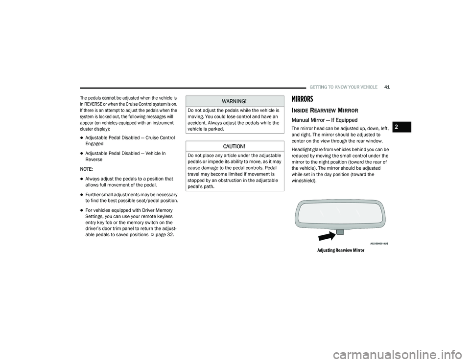
The mirror head can be adjusted up, down, left,
and right. The mirror should be adjusted to
center on the view through the rear window.
Headlight glare from vehicles behind you can be
reduced by moving the small control under the
mirror to the night position (toward the rear of
the vehicle). The mirror should be adjusted
while set in the day position (toward the
windshield).
Adjusting Rearview Mirror
WARNING!
Do not adjust the pedals while the vehicle is
moving. You could lose control and have an
accident. Always adjust the pedals while the
vehicle is parked.
CAUTION!
Do not place any article under the adjustable
pedals or impede its ability to move, as it may
cause damage to the pedal controls. Pedal
travel may become limited if movement is
stopped by an obstruction in the adjustable
pedal's path.
2
21_DPF_OM_EN_USC_t.book Page 41
Page 44 of 463
42GETTING TO KNOW YOUR VEHICLE
Automatic Dimming Mirror — If Equipped
The mirror head can be adjusted up, down, left,
and right. The mirror should be adjusted to
center on the view through the rear window.
This mirror automatically adjusts for headlight
glare from vehicles behind you.
NOTE:
The Automatic Dimming feature is disabled
when the vehicle is in REVERSE to improve rear
view viewing.
The Automatic Dimming feature can be turned
on or off through the touchscreen.
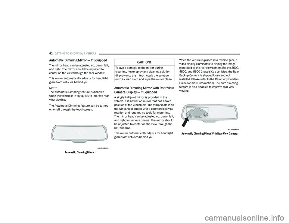
Automatic Dimming Mirror
Automatic Dimming Mirror With Rear View
Camera Display — If Equipped
A single ball joint mirror is provided in the
vehicle. It is a twist on mirror that has a fixed
position at the windshield. The mirror installs on
the windshield button with a counterclockwise
rotation and requires no tools for mounting.
The mirror head can be adjusted up, down, left,
and right for various drivers. The mirror should
be adjusted to center on the view through the
rear window.
This mirror automatically adjusts for headlight
glare from vehicles behind you.
When the vehicle is placed into reverse gear, a
video display illuminates to display the image
generated by the rear view camera (for the 3500,
4500, and 5500 Chassis Cab vehicles, the Rear
Backup Camera is shipped loose and not
installed. Please refer to the Ram Body Builders
Guide for more information). The auto dimming
feature is also disabled to improve rear view
viewing.
Automatic Dimming Mirror With Rear View Camera
CAUTION!
To avoid damage to the mirror during
cleaning, never spray any cleaning solution
directly onto the mirror. Apply the solution
onto a clean cloth and wipe the mirror clean.
21_DPF_OM_EN_USC_t.book Page 42
Page 45 of 463
GETTING TO KNOW YOUR VEHICLE43
Digital Rearview Mirror — If Equipped
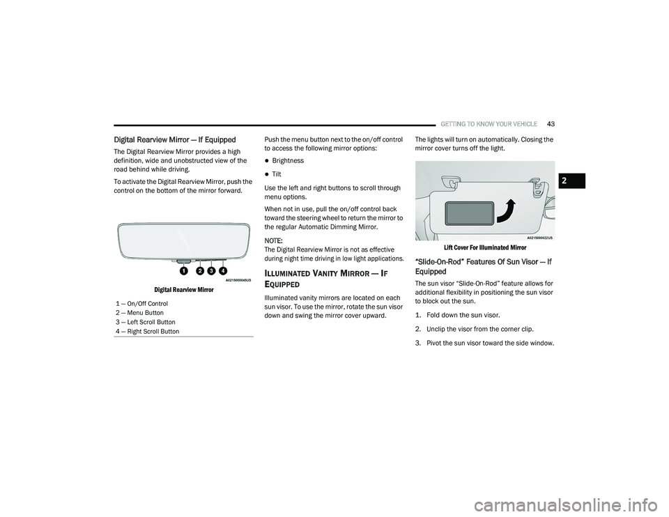
The Digital Rearview Mirror provides a high
definition, wide and unobstructed view of the
road behind while driving.
To activate the Digital Rearview Mirror, push the
control on the bottom of the mirror forward.
Digital Rearview Mirror
Push the menu button next to the on/off control
to access the following mirror options:
Brightness
Tilt
Use the left and right buttons to scroll through
menu options.
When not in use, pull the on/off control back
toward the steering wheel to return the mirror to
the regular Automatic Dimming Mirror.
NOTE:
The Digital Rearview Mirror is not as effective
during night time driving in low light applications.
ILLUMINATED VANITY MIRROR — IF
E
QUIPPED
Illuminated vanity mirrors are located on each
sun visor. To use the mirror, rotate the sun visor
down and swing the mirror cover upward. The lights will turn on automatically. Closing the
mirror cover turns off the light.
Lift Cover For Illuminated Mirror
“Slide-On-Rod” Features Of Sun Visor — If
Equipped
The sun visor “Slide-On-Rod” feature allows for
additional flexibility in positioning the sun visor
to block out the sun.
1. Fold down the sun visor.
2. Unclip the visor from the corner clip.
3. Pivot the sun visor toward the side window.
1 — On/Off Control
2 — Menu Button
3 — Left Scroll Button
4 — Right Scroll Button
2
21_DPF_OM_EN_USC_t.book Page 43
Page 54 of 463
52GETTING TO KNOW YOUR VEHICLE
AUTOMATIC HIGH BEAM HEADLAMP
C
ONTROL — IF EQUIPPED
The Automatic High Beam Headlamp Control
system provides increased forward lighting at
night by automating high beam control through
the use of a camera mounted on the inside
rearview mirror or a windshield mounted
camera. These cameras detect vehicle specific
light and automatically switch from high beams
to low beams until the approaching vehicle is
out of view.
NOTE:
The Automatic High Beam Headlamp Control can
be turned on or off by selecting “ON” under “Auto
Dim High Beams” within your Uconnect Settings
Ú
page 228, as well as turning the headlight
switch to the AUTO position.
Broken, muddy, or obstructed headlights and
taillights of vehicles in the field of view will
cause headlights to remain on longer (closer to
the vehicle). Also, dirt, film, and other obstruc -
tions on the windshield or camera lens will
cause the system to function improperly.
If the windshield or Automatic High Beam
Headlamp Control mirror is replaced, the
mirror must be re-aimed to ensure proper
performance. See a local authorized dealer.
To opt out of the Advanced Auto High Beam
Sensitivity Control (default) and enter
Reduced High Beam Sensitivity Control (not
recommended), on vehicles equipped with
mirror controlled automatic high beams and
without the forward facing camera, toggle the
high beam lever six full on/off cycles within
10 seconds of placing the ignition in the ON
position. The system will return to the default
setting when the ignition is placed in the OFF
position.
FLASH-TO-PASS
You can signal another vehicle with your
headlights by lightly pulling the multifunction
lever toward you. This will cause the high beam
headlights to turn on, and remain on, until the
lever is released.
AUTOMATIC HEADLIGHTS — IF EQUIPPED
This system automatically turns your headlights
on or off based on ambient light levels. To turn
the system on, rotate the headlight switch to the
AUTO position.
When the system is on, the Headlight Delay
feature is also on. This means the headlights
will stay on for up to 90 seconds after you place
the ignition into the OFF position. To turn the
automatic headlights off, turn the headlight
switch out of the AUTO position.
NOTE:
The engine must be running before the head -
lights will come on in the Automatic mode.
DIRECTIONAL LED HEADLAMP
S
YSTEM — IF EQUIPPED
This is a system consisting of LED (low/high
beam) headlights that incorporate dynamic
cornering with 5-degree inboard/15-degree
outboard swivel. The headlights continuously and
automatically adapt to the driving conditions
around bends or when cornering based on
steering wheel angle.
21_DPF_OM_EN_USC_t.book Page 52
Page 108 of 463
106GETTING TO KNOW YOUR INSTRUMENT PANEL
NOTE:
The charging system is independent from
load reduction. The charging system
performs a diagnostic on the charging
system continuously.
If the Battery Charge Warning Light is on it
may indicate a problem with the charging
system Úpage 108.
The electrical loads that may be switched off
(if equipped), and vehicle functions which can
be affected by load reduction:
Heated Seats/Vented Seats/Heated Wheel
Rear Defroster And Heated Mirrors
HVAC System
115 Volt AC Power Inverter System
Audio and Telematics System
Loss of the battery charge may indicate one or
more of the following conditions:
The charging system cannot deliver enough
electrical power to the vehicle system because
the electrical loads are larger than the capa -
bility of charging system. The charging system
is still functioning properly.
Turning on all possible vehicle electrical
loads (e.g. HVAC to max settings, exterior
and interior lights, overloaded power outlets
+12 Volts, 115 Volt AC, USB ports) during
certain driving conditions (city driving,
towing, frequent stopping).
Installing options like additional lights,
upfitter electrical accessories, audio
systems, alarms and similar devices.
Unusual driving cycles (short trips separated
by long parking periods).
The vehicle was parked for an extended
period of time (weeks, months).
The battery was recently replaced and was
not charged completely.
The battery was discharged by an electrical
load left on when the vehicle was parked.
The battery was used for an extended period
with the engine not running to supply radio,
lights, chargers, +12 Volt portable appli -
ances like vacuum cleaners, game consoles
and similar devices. What to do when an electrical load reduction
action message is present (“Battery Saver On”
or “Battery Saver Mode”)
During a trip:
Reduce power to unnecessary loads if
possible:
Turn off redundant lights (interior or exterior).
Check what may be plugged in to power
outlets +12 Volts, 115 Volt AC, USB ports.
Check HVAC settings (blower, temperature).
Check the audio settings (volume).
After a trip:
Check if any aftermarket equipment was
installed (additional lights, upfitter electrical
accessories, audio systems, alarms) and
review specifications if any (load and Ignition
Off Draw currents).
Evaluate the latest driving cycles (distance,
driving time and parking time).
The vehicle should have service performed if the
message is still present during consecutive trips
and the evaluation of the vehicle and driving
pattern did not help to identify the cause.
21_DPF_OM_EN_USC_t.book Page 106
Page 175 of 463
STARTING AND OPERATING173 If the vehicle in front does not start moving
within two seconds of your vehicle coming to a
standstill, the ACC with Stop system will
cancel and the brakes will release. A cancel
message will display on the instrument cluster
display and produce a warning chime. The
driver must now manually operate the
vehicle's accelerator and brakes.
While ACC is holding your vehicle at a
standstill, if the driver seat belt is unbuckled
or the driver door is opened, the ACC system
will cancel and the brakes will release. Driver
intervention will be required at this moment.
Display Warnings And Maintenance
“Wipe Front Radar Sensor In Front Of Vehicle”
Warning
The “ACC/FCW Unavailable Wipe Front Radar
Sensor” warning will display and a chime will
sound when conditions temporarily limit system
performance.
This most often occurs at times of poor visibility,
such as in snow or heavy rain. The ACC system
may also become temporarily blinded due to
obstructions, such as mud, dirt or ice. In these
cases, the instrument cluster display will display
“ACC/FCW Unavailable Wipe Front Radar
Sensor” and the system will deactivate.
This message can sometimes be displayed while
driving in highly reflective areas (i.e. ice and snow, or
tunnels with reflective tiles). The ACC system will
recover after the vehicle has left these areas. Under
rare conditions, when the radar is not tracking any
vehicles or objects in its path this warning may
temporarily occur.
NOTE:
If the “ACC/FCW Unavailable Wipe Front Radar
Sensor” warning is active, Fixed Speed Cruise
Control is still available.
If weather conditions are not a factor, the driver
should examine the sensor. It may require
cleaning or removal of an obstruction. The sensor
is located in the camera in the center of the
windshield, on the forward side of the rearview
mirror.
To keep the ACC system operating properly, it is
important to note the following maintenance
items:
Always keep the sensor clean. Carefully clear
the windshield.
Do not remove any screws from the sensor.
Doing so could cause an ACC system
malfunction or failure and require a sensor
realignment.
Do not attach or install any accessories near
the sensor, including transparent material or
aftermarket grilles. Doing so could cause an
ACC system failure or malfunction.
WARNING!
When the ACC system is resumed, the driver
must ensure that there are no pedestrians,
vehicles or objects in the path of the vehicle.
Failure to follow these warnings can result in a
collision and death or serious personal injury.
4
21_DPF_OM_EN_USC_t.book Page 173
Page 176 of 463
174STARTING AND OPERATING
When the condition that deactivated the system
is no longer present, the system will return to
the “Adaptive Cruise Control Off” state and will
resume function by simply reactivating it.
NOTE:
If the “ACC/FCW Unavailable Wipe Front
Radar Sensor” message occurs frequently
(e.g. more than once on every trip) without
any snow, rain, mud, or other obstruction,
have the radar sensor realigned at an autho -
rized dealer.
Installing a snow plow, front-end protector,
an aftermarket grille or modifying the grille is
not recommended. Doing so may block the
sensor and inhibit ACC/FCW operation. “Clean Front Windshield” Warning
The “ACC/FCW Limited Functionality Clean
Front Windshield” warning will display and a
chime will sound when conditions temporarily
limit system performance. This most often
occurs at times of poor visibility, such as in
snow or heavy rain and fog. The ACC system
may also become temporarily blinded due to
obstructions, such as mud, dirt, or ice on
windshield, driving directly into the sun and fog
on the inside of glass. In these cases, the
instrument cluster display will show “ACC/FCW
Limited Functionality Clean Front Windshield”
and the system will have degraded
performance.
This message can sometimes be displayed
while driving in adverse weather conditions.
The ACC/FCW system will recover after the
vehicle has left these areas. Under rare
conditions, when the camera is not tracking
any vehicles or objects in its path this warning
may temporarily occur. If weather conditions are not a factor, the driver
should examine the windshield and the camera
located on the back side of the inside rearview
mirror. They may require cleaning or removal of
an obstruction.
When the condition that created limited
functionality is no longer present, the system
will return to full functionality.
NOTE:
If the “ACC/FCW Limited Functionality Clean
Front Windshield” message occurs frequently
(e.g. more than once on every trip) without any
snow, rain, mud, or other obstruction, have
the windshield and forward facing camera
inspected at an authorized dealer.
21_DPF_OM_EN_USC_t.book Page 174
Page 191 of 463
STARTING AND OPERATING189
Zoom View is not available with the AUX
Camera feature.
The display will always default to the Trailer
Camera display (AUX 1).
SURROUND VIEW CAMERA SYSTEM — IF
EQUIPPED
Your vehicle may be equipped with the Surround
View Camera system that allows you to see an
on-screen image of the surroundings and Top
View of your vehicle whenever the gear selector is
put into REVERSE or manually activated via the
Uconnect system. The Top View of the vehicle will
show which doors are open. The image will be
displayed on the touchscreen display along with
a caution note “Check Entire Surroundings”
across the top of the screen. After five seconds,
this note will disappear. The Surround View
Camera system is comprised of three sequential
cameras located in the front grille and side
mirrors, in addition to a fourth Rear Back Up
Camera.
NOTE:
For the 3500, 4500, and 5500 Chassis Cab vehi
-
cles, the Rear Backup Camera is shipped loose
and not installed. Please refer to the Ram Body
Builder’s Guide for more information.
The Surround View Camera system has
programmable settings that may be selected
through the Uconnect system Ú page 228.
Press this button on the touchscreen
to enter the Surround View Camera
menu in the Uconnect system.
When the vehicle is shifted into REVERSE, the
Rear View and Top View is the default view of
the system.
If the camera delay is turned on, the camera
image will display for up to 10 seconds after
shifting out of REVERSE. The camera image will
not display for 10 seconds if the vehicle speed
exceeds 8 mph (13 km/h), the vehicle is shifted
into PARK, or the ignition is placed in the OFF
position. The “X” button on the touchscreen
disables the display of the camera image.
If the camera delay is turned off, the camera
image will close and display the previous screen
after shifting out of REVERSE. If active guidelines are enabled, the lines are
overlaid on the image in the Rear View to
illustrate the width of the vehicle. The view
will also include the side view mirrors and its
projected back up path based on the steering
wheel position.
There are different colored zones to indicate the
distance to the rear of the vehicle. Refer to the
chart below:
Modes Of Operation
Standard Rear View can be manually activated
by selecting “Back Up Camera” through the
Controls menu within the Uconnect system.
Top View
The Top View will show in the Uconnect system
with Rear View and Front View in a split screen
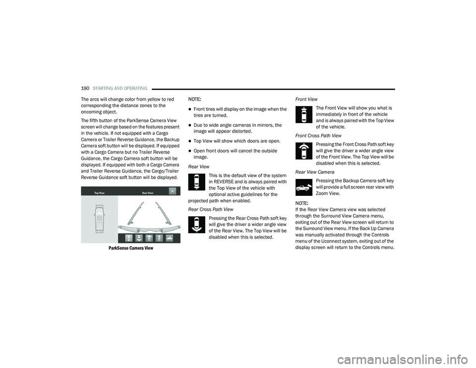
display. There are integrated ParkSense arcs in
the image at the front and rear of the vehicle.
Zone
Distance To The Rear Of The
Vehicle
Red 0 - 1 ft (0 - 30 cm)
Yellow 1 ft - 6.5 ft (30 cm - 2 m)
Green 6.5 ft or greater
(2 m or greater)
4
21_DPF_OM_EN_USC_t.book Page 189
Page 192 of 463
190STARTING AND OPERATING
The arcs will change color from yellow to red
corresponding the distance zones to the
oncoming object.
The fifth button of the ParkSense Camera View
screen will change based on the features present
in the vehicle. If not equipped with a Cargo
Camera or Trailer Reverse Guidance, the Backup
Camera soft button will be displayed. If equipped
with a Cargo Camera but no Trailer Reverse
Guidance, the Cargo Camera soft button will be
displayed. If equipped with both a Cargo Camera
and Trailer Reverse Guidance, the Cargo/Trailer
Reverse Guidance soft button will be displayed.
ParkSense Camera View
NOTE:
Front tires will display on the image when the
tires are turned.
Due to wide angle cameras in mirrors, the
image will appear distorted.
Top View will show which doors are open.
Open front doors will cancel the outside
image.
Rear View This is the default view of the system
in REVERSE and is always paired with
the Top View of the vehicle with
optional active guidelines for the
projected path when enabled.
Rear Cross Path View
Pressing the Rear Cross Path soft key
will give the driver a wider angle view
of the Rear View. The Top View will be
disabled when this is selected. Front View
The Front View will show you what is
immediately in front of the vehicle
and is always paired with the Top View
of the vehicle.
Front Cross Path View Pressing the Front Cross Path soft key
will give the driver a wider angle view
of the Front View. The Top View will be
disabled when this is selected.
Rear View Camera Pressing the Backup Camera soft key
will provide a full screen rear view with
Zoom View.
NOTE:
If the Rear View Camera view was selected
through the Surround View Camera menu,
exiting out of the Rear View screen will return to
the Surround View menu. If the Back Up Camera
was manually activated through the Controls
menu of the Uconnect system, exiting out of the
display screen will return to the Controls menu.
21_DPF_OM_EN_USC_t.book Page 190