clock RAM CHASSIS CAB 2022 User Guide
[x] Cancel search | Manufacturer: RAM, Model Year: 2022, Model line: CHASSIS CAB, Model: RAM CHASSIS CAB 2022Pages: 428, PDF Size: 20.18 MB
Page 319 of 428

IN CASE OF EMERGENCY317
Jack Warning Label
1. If equipped, remove the spare wheel and tools from storage.
2. Using the lug wrench, loosen, but do not remove, the lug nuts by turning them counter -
clockwise one turn while the wheel is still on
the ground.
3. When changing the front wheel, place the jack under the axle as close to the tire as possible.
Front Jacking Locations
When changing a rear wheel, securely place
the jack under the sway bar bracket (unless
both tires are flat on one side, then place jack
under shock bracket) facing forward in vehicle.
Rear Jacking Location
Before raising the wheel off the ground, make
sure that the jack will not damage surrounding
truck parts and adjust the jack position as re
-
quired.
4. Raise the vehicle until the wheel just clears the surface.
5. Remove the lug nuts and pull the wheel off. For Single Rear-Wheel (SRW) models, Install the
spare wheel and lug nuts with the cone shaped
end of the nuts toward the wheel. For Dual
Rear-Wheel (DRW) models, the lug nuts are a
two-piece assembly with a flat face. Lightly
tighten the nuts. To avoid risk of forcing the
vehicle off the jack, do not fully tighten the
nuts until the vehicle has been lowered.
6. Using the lug wrench, finish tightening the nuts using a crisscross pattern Ú page 397. If in
doubt about the correct tightness, have them
checked with a torque wrench by an
authorized dealer or at a service station.
CAUTION!
Do not attempt to raise the vehicle by jacking on
locations other than those indicated in the
Jacking Instructions for this vehicle.
WARNING!
Raising the vehicle higher than necessary can
make the vehicle less stable. It could slip off the
jack and hurt someone near it. Raise the vehicle
only enough to remove the tire.
7
22_DPF_OM_EN_USC_t.book Page 317
Page 350 of 428

348SERVICING AND MAINTENANCE
station, or government agency for advice on recy -
cling programs and for where used fluids and
filters can be properly disposed of in your area.
Drain the fuel/water separator filters when the
“Water In Fuel Indicator Light” is ON. Within
10 minutes of vehicle shutdown, turn the engine
mounted filter drain valve (located on the side of
the filter assembly) counterclockwise a quarter
turn, and turn the under body mounted filter drain
valve (located on the bottom of the filter assembly)
counterclockwise 1 full turn. Then turn the ignition
switch to the ON position, and allow any
accumulated water to drain. Leave the drain valve
open until all water and contaminants have been
removed. When clean fuel is visible, close the drain
valve following these guidelines:
1. Rotate the drain clockwise to close until you feel resistance from the internal seal.
2. Continue turning the drain half of a turn to properly compress the seal.
NOTE:Over-compression of the seal due to overtightening
of the drain will damage the seal, cause a leak, and
require the entire sensor to be replaced.
3. Turn the ignition switch to OFF. The sensor drain should not be overtightened
during normal service operations to avoid internal
damage and future fuel leaks. The drain should be
closed and secured without the use of tools.
If more than a couple ounces/milliliters of fuel
have been drained, follow the directions
Ú
page 350
ENGINE MOUNTED FUEL FILTER
R
EPLACEMENT
NOTE:
Using a fuel filter that does not meet the manu -
facturer's filtration and water separating
requirements can severely impact fuel system
life and reliability.
The engine mounted filter housing is equipped
with a No-Filter-No-Run (NFNR) feature. Engine
will not run if:
No filter is installed.
Inferior/Non-approved filter is used. Use of
OEM filter is required to ensure vehicle will
run.
Engine Mounted Fuel Filter Assembly
1 — Drain Valve
CAUTION!
Diesel fuel will damage blacktop paving
surfaces. Drain the filter into an appropriate
container.
Do not prefill the fuel filter when installing a
new fuel filter. There is a possibility debris
could be introduced into the fuel filter during
this action. It is best to install the filter dry and
allow the in-tank lift pump to prime the fuel
system.
22_DPF_OM_EN_USC_t.book Page 348
Page 351 of 428

SERVICING AND MAINTENANCE349
1. Ensure engine is turned off.
2. Place drain pan under the fuel filter drain hose.
3. Open the water drain valve a quarter turn counterclockwise and completely drain fuel
and water into the approved container.
4. Close the water drain valve.
5. Remove lid using a socket or strap wrench. Rotate counterclockwise for removal. Remove
used o-ring and discard it.
6. Remove the used filter cartridge from the housing and dispose of according to your local
regulations.
7. Wipe clean the sealing surfaces of the lid and housing.
8. Install new o-ring back into ring groove on the filter housing and lubricate with clean engine
oil.
9. Remove new filter cartridge from plastic bag and install into housing.
NOTE:Do not remove cartridge from bag until you reach
this step in order to keep cartridge clean.
10. Push down on the cartridge to ensure it is properly seated. Do not pre-fill the filter
housing with fuel. 11. Install lid onto housing and tighten to 22.5 ft lb
(30.5 N.m). Do not overtighten the lid.
12. Prime the engine, then start the engine and confirm there are no leaks Ú page 350.
UNDERBODY MOUNTED FUEL FILTER
R
EPLACEMENT
NOTE:
Using a fuel filter that does not meet the manu -
facturer's filtration and water separating
requirements can severely impact fuel system
life and reliability.
The underbody mounted filter housing will
cause the engine not to run if:
a. No filter is installed.
Underbody Mounted Fuel Filter Assembly
1. Ensure engine is turned off.
2. Place drain pan under the fuel filter drain hose.
3. Open the water drain valve one full turn
counterclockwise and completely drain fuel
and water into the approved container.
4. Close the water drain valve.
5. Remove lid using a socket or strap wrench. Rotate counterclockwise for removal. Remove
used o-ring and discard it.
6. Remove the used filter cartridge from the housing and dispose of according to your local
regulations.
7. Wipe clean the sealing surfaces of the lid and housing.
1 — Drain Valve
CAUTION!
Diesel fuel will damage blacktop paving
surfaces. Drain the filter into an appropriate
container.
Do not prefill the fuel filter when installing a
new fuel filter. There is a possibility debris
could be introduced into the fuel filter during
this action. It is best to install the filter dry and
allow the in-tank lift pump to prime the fuel
system.
8
22_DPF_OM_EN_USC_t.book Page 349
Page 375 of 428

SERVICING AND MAINTENANCE373
Replacing Exterior Bulbs
BASE QUAD: LOW BEAM HEADLAMP, HIGH
BEAM HEADLAMP, FRONT PARK AND TURN —
IF EQUIPPED
Low Beam
See below steps to replace:
1. Open the hood.
2. Disconnect and isolate the negative battery
cable.
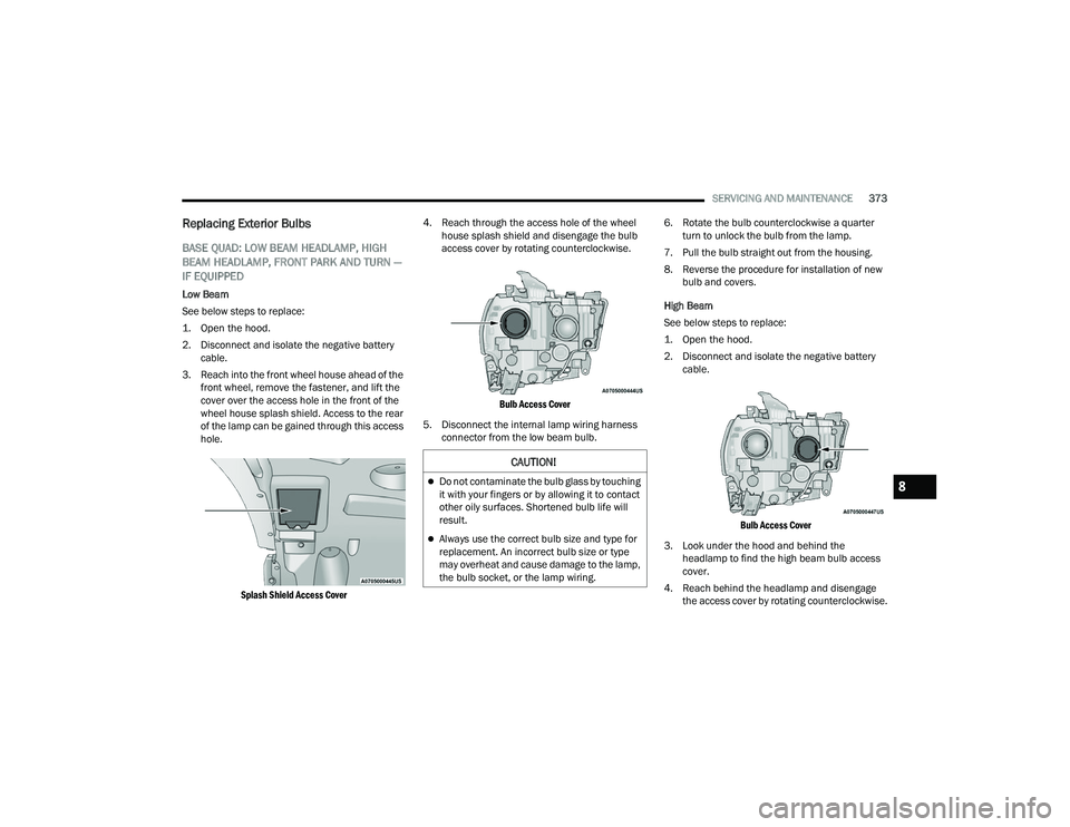
3. Reach into the front wheel house ahead of the front wheel, remove the fastener, and lift the
cover over the access hole in the front of the
wheel house splash shield. Access to the rear
of the lamp can be gained through this access
hole.
Splash Shield Access Cover
4. Reach through the access hole of the wheel
house splash shield and disengage the bulb
access cover by rotating counterclockwise.
Bulb Access Cover
5. Disconnect the internal lamp wiring harness connector from the low beam bulb. 6. Rotate the bulb counterclockwise a quarter
turn to unlock the bulb from the lamp.
7. Pull the bulb straight out from the housing.
8. Reverse the procedure for installation of new bulb and covers.
High Beam
See below steps to replace:
1. Open the hood.
2. Disconnect and isolate the negative battery cable.
Bulb Access Cover
3. Look under the hood and behind the headlamp to find the high beam bulb access
cover.
4. Reach behind the headlamp and disengage the access cover by rotating counterclockwise.
CAUTION!
Do not contaminate the bulb glass by touching
it with your fingers or by allowing it to contact
other oily surfaces. Shortened bulb life will
result.
Always use the correct bulb size and type for
replacement. An incorrect bulb size or type
may overheat and cause damage to the lamp,
the bulb socket, or the lamp wiring.
8
22_DPF_OM_EN_USC_t.book Page 373
Page 376 of 428

374SERVICING AND MAINTENANCE
5. Disconnect the internal lamp wiring harness connector from the high beam bulb.
6. Rotate the bulb counterclockwise a quarter turn to unlock the bulb from the lamp.
7. Pull the bulb straight out from the housing.
8. Reverse the procedure for installation of new bulb and covers.
Outer Park And Turn
See below steps to replace:
1. Open the hood.
2. Disconnect and isolate the negative battery cable.
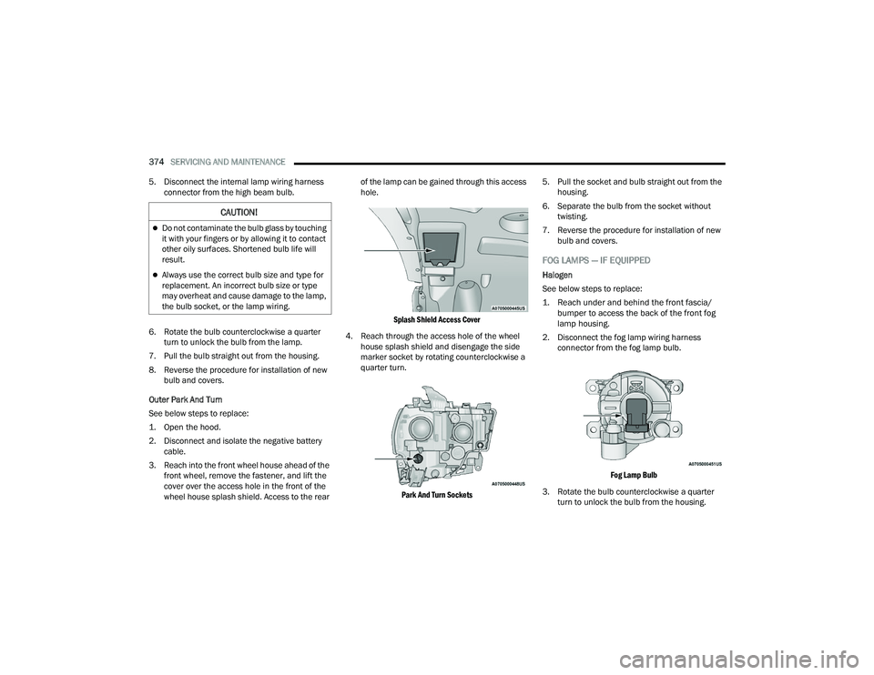
3. Reach into the front wheel house ahead of the front wheel, remove the fastener, and lift the
cover over the access hole in the front of the
wheel house splash shield. Access to the rear of the lamp can be gained through this access
hole.
Splash Shield Access Cover
4. Reach through the access hole of the wheel house splash shield and disengage the side
marker socket by rotating counterclockwise a
quarter turn.
Park And Turn Sockets
5. Pull the socket and bulb straight out from the
housing.
6. Separate the bulb from the socket without twisting.
7. Reverse the procedure for installation of new bulb and covers.
FOG LAMPS — IF EQUIPPED
Halogen
See below steps to replace:
1. Reach under and behind the front fascia/bumper to access the back of the front fog
lamp housing.
2. Disconnect the fog lamp wiring harness connector from the fog lamp bulb.
Fog Lamp Bulb
3. Rotate the bulb counterclockwise a quarter turn to unlock the bulb from the housing.
CAUTION!
Do not contaminate the bulb glass by touching
it with your fingers or by allowing it to contact
other oily surfaces. Shortened bulb life will
result.
Always use the correct bulb size and type for
replacement. An incorrect bulb size or type
may overheat and cause damage to the lamp,
the bulb socket, or the lamp wiring.
22_DPF_OM_EN_USC_t.book Page 374