torque RAM CHASSIS CAB 2022 User Guide
[x] Cancel search | Manufacturer: RAM, Model Year: 2022, Model line: CHASSIS CAB, Model: RAM CHASSIS CAB 2022Pages: 428, PDF Size: 20.18 MB
Page 138 of 428

136STARTING AND OPERATING
This electronically shifted transfer case is designed
to be driven in the two-wheel drive position (2WD)
for normal street and highway conditions on dry,
hard surfaced roads.
When additional traction is required, the transfer
case 4WD HIGH and 4WD LOW positions can be
used to maximize torque to the front driveshaft,
forcing the front and rear wheels to rotate at the
same speed. This is accomplished by rotating the
four-wheel drive Control Switch to the desired
position.
For specific shifting instructions Ú page 137.
The 4WD HIGH and 4WD LOW positions are
designed for loose, slippery road surfaces only.
Driving in the 4WD HIGH and 4WD LOW positions
on dry hard surfaced roads may cause increased
tire wear and damage to the driveline components.
NOTE:The transfer case N (Neutral) button is located on
the lower left hand corner of the four-wheel drive
Control Switch. The transfer case N (Neutral)
position is to be used for recreational towing only
Ú page 185.
Transfer Case Position Indicator Lights
The Transfer Case Position Indicator Lights (4WD
and 4WD LOW) are located in the instrument
cluster and indicate the current and desired
transfer case selection. When you select a different transfer case position, the indicator lights
will do the following:
If All Of The Following Shift Conditions Are Met:
1. The current position indicator light will turn off.
2. The selected position indicator light will flash until the transfer case completes the shift.
3. When the shift is complete, the indicator light for the selected position will stop flashing and
remain on.
If One Or More Of The Following Shift Conditions
Are Not Met:
1. The indicator light for the current position will remain on.
2. The newly selected position indicator light will continue to flash.
3. The transfer case will not shift.
NOTE:Before retrying a selection, make certain that all
the necessary requirements for selecting a new
transfer case position have been met. To retry the
selection, turn the control switch back to the
current position, wait five seconds, and retry
selection Ú page 137.
The SERV 4WD Warning Light monitors the
electronically shifted four-wheel drive system. If
this light remains on after engine start-up or illuminates during driving, it means that the
four-wheel drive system is not functioning properly
and that service is required.
NOTE:Do not attempt to make a shift while only the front
or rear wheels are spinning, as this can cause
damage to driveline components.
When operating your vehicle in 4WD LOW, the
engine speed is approximately three times that of
the two-wheel drive or 4WD HIGH positions at a
given road speed. Take care not to overspeed the
engine and do not exceed 25 mph (40 km/h).
Proper operation of four-wheel drive vehicles
depends on tires of equal size, type and
circumference on each wheel. Any difference in
tire size can cause damage to the drivetrain.
Because four-wheel drive provides improved
traction, there is a tendency to exceed safe turning
and stopping speeds. Do not go faster than road
conditions permit.
WARNING!
Always engage the parking brake when powering
down the vehicle if the SERV 4WD Warning Light
is illuminated. Not engaging the parking brake
may allow the vehicle to roll, which may cause
personal injury.
22_DPF_OM_EN_USC_t.book Page 136
Page 158 of 428

156STARTING AND OPERATING
(Continued)
ParkSense system might not detect an obstacle
behind or in front of the fascia/bumper, or it
could provide a false indication that an obstacle
is behind or in front of the fascia/bumper.
Use the ParkSense switch to turn the ParkSense
system off if obstacles such as bicycle carriers,
trailer hitches, etc. are placed within 18 inches
(45 cm) of the rear fascia/bumper. Failure to do
so can result in the system misinterpreting a
close obstacle as a sensor problem, causing the
“Front/Rear ParkSense Unavailable Service
Required” message to be appear in the instru
-
ment cluster display.
LANESENSE — IF EQUIPPED
LANESENSE OPERATION
The LaneSense system is operational at speeds
above 37 mph (60 km/h) and below 112 mph
(180 km/h). It uses a forward looking camera to
detect lane markings and measure vehicle
position within the lane boundaries.
When both lane markings are detected and the
driver drifts out of the lane (no turn signal has been
applied) OR the driver departs the lane on the
opposite side of the applied turn signal (if the left
turn signal is applied and the vehicle departs to the
right), the LaneSense system provides a haptic
warning in the form of torque applied to the
steering wheel, as well as a visual warning in the
instrument cluster display to prompt the driver to
remain within the lane boundaries.
The driver may manually override the haptic
warning by applying torque to the steering wheel at
any time.
When only a single lane marking is detected and
the driver drifts across that lane marking (no turn
signal applied), the LaneSense system provides a
visual warning through the instrument cluster
display to prompt the driver to remain within the
lane.
When only a single lane marking is detected, a
haptic (torque) warning will not be provided.
WARNING!
Drivers must be careful when backing up even
when using ParkSense. Always check carefully
behind your vehicle, look behind you, and be
sure to check for pedestrians, animals, other
vehicles, obstructions, and blind spots before
backing up. You are responsible for safety and
must continue to pay attention to your
surroundings. Failure to do so can result in
serious injury or death.
Before using ParkSense, it is strongly recom -
mended that the ball mount and hitch ball
assembly be disconnected from the vehicle
when the vehicle is not used for towing.
Failure to do so can result in injury or damage
to vehicles or obstacles because the hitch ball
will be much closer to the obstacle than the
rear fascia when the vehicle sounds the
continuous tone. Also, the sensors could
detect the ball mount and hitch ball assembly,
depending on its size and shape, giving a false
indication that an obstacle is behind the
vehicle.
CAUTION!
ParkSense is only a parking aid and it is
unable to recognize every obstacle, including
small obstacles. Parking curbs might be
temporarily detected or not detected at all.
Obstacles located above or below the sensors
will not be detected when they are in close
proximity.
The vehicle must be driven slowly when using
ParkSense in order to be able to stop in time
when an obstacle is detected. It is recom -
mended that the driver looks over his/her
shoulder when using ParkSense.
WARNING!
22_DPF_OM_EN_USC_t.book Page 156
Page 160 of 428
158STARTING AND OPERATING
Left Lane Departure — Both Lane Lines Detected
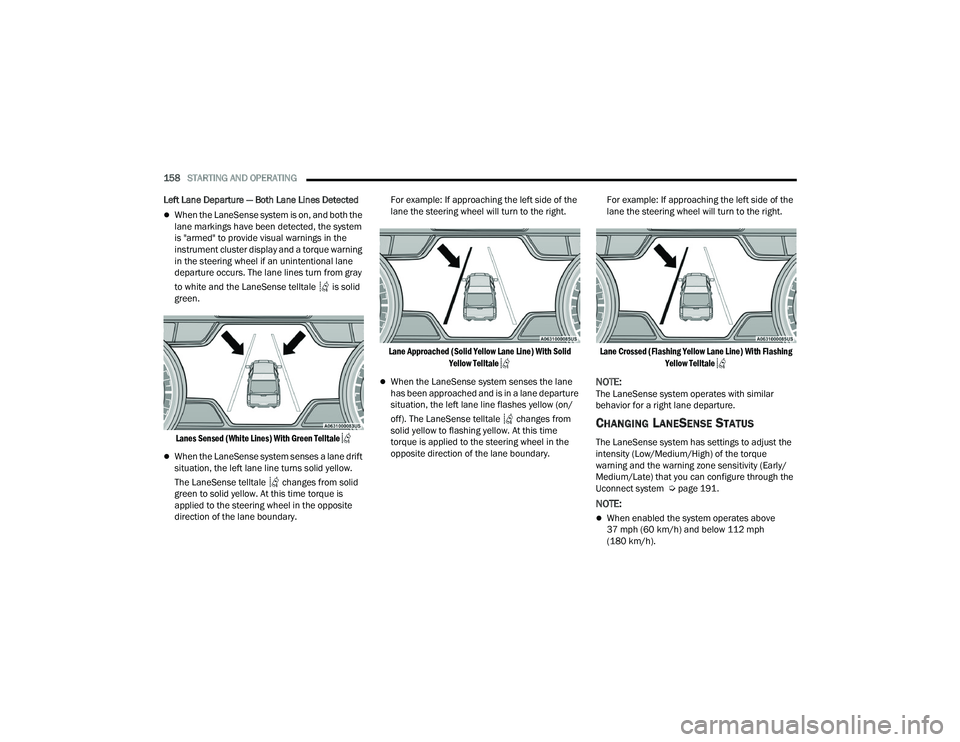
When the LaneSense system is on, and both the
lane markings have been detected, the system
is "armed" to provide visual warnings in the
instrument cluster display and a torque warning
in the steering wheel if an unintentional lane
departure occurs. The lane lines turn from gray
to white and the LaneSense telltale is solid
green.
Lanes Sensed (White Lines) With Green Telltale
When the LaneSense system senses a lane drift
situation, the left lane line turns solid yellow.
The LaneSense telltale changes from solid
green to solid yellow. At this time torque is
applied to the steering wheel in the opposite
direction of the lane boundary. For example: If approaching the left side of the
lane the steering wheel will turn to the right.
Lane Approached (Solid Yellow Lane Line) With Solid Yellow Telltale
When the LaneSense system senses the lane
has been approached and is in a lane departure
situation, the left lane line flashes yellow (on/
off). The LaneSense telltale changes from
solid yellow to flashing yellow. At this time
torque is applied to the steering wheel in the
opposite direction of the lane boundary. For example: If approaching the left side of the
lane the steering wheel will turn to the right.
Lane Crossed (Flashing Yellow Lane Line) With Flashing Yellow Telltale
NOTE:The LaneSense system operates with similar
behavior for a right lane departure.
CHANGING LANESENSE STATUS
The LaneSense system has settings to adjust the
intensity (Low/Medium/High) of the torque
warning and the warning zone sensitivity (Early/
Medium/Late) that you can configure through the
Uconnect system Ú page 191.
NOTE:
When enabled the system operates above
37 mph (60 km/h) and below 112 mph
(180 km/h).
22_DPF_OM_EN_USC_t.book Page 158
Page 161 of 428
STARTING AND OPERATING159
Use of the turn signal suppresses the warnings.
The system will not apply torque to the steering
wheel whenever a safety system engages
(Anti-Lock Brakes, Traction Control System,
Electronic Stability Control, Forward Collision
Warning, etc.).
PARKVIEW REAR BACK UP CAMERA
The ParkView Rear Back Up Camera allows you to
see an on-screen image of the rear surroundings of
your vehicle whenever the gear selector is put into
REVERSE. The image will be displayed on the
Uconnect display along with a caution note to
“Check Entire Surroundings” across the top of the
screen. After five seconds this note will disappear.
The ParkView Camera is located in the center of
the tailgate handle.
NOTE:For the 3500, 4500, and 5500 Chassis Cab
vehicles, the Rear Backup Camera is shipped
loose and not installed. Please refer to the Ram
Body Builder’s Guide for more information.
Manual Activation Of The Rear View
Camera:
1. Press the "Controls" button located on the bottom of the Uconnect display.
2. Press the "Back Up Camera" icon to turn the Rear View Camera system on. When the vehicle is shifted out of REVERSE (with
camera delay turned off), the rear camera mode is
exited and the previous screen appears. When the
vehicle is shifted out of REVERSE (with camera
delay turned on), the camera image will continue to
be displayed for up to 10 seconds unless the
following conditions occur: The vehicle speed
exceeds 8 mph (13 km/h), the vehicle is shifted
into PARK, the vehicle’s ignition is placed in the
OFF position, or the user presses image defeat “X”
to exit out of the camera video display.
Whenever the Rear View Camera image is
activated through the "Backup Camera" button in
the Controls menu, and the vehicle speed is
greater than, or equal to, 8 mph (13 km/h), a
display timer for the image is initiated. The image
will continue to be displayed until the display timer
exceeds 10 seconds.NOTE:
If the vehicle speed remains below 8 mph
(13 km/h), the Rear View Camera image will be
displayed continuously until deactivated via the
touchscreen button "X", the transmission is
shifted into PARK, or the ignition is placed in the
OFF position.
The touchscreen button "X" to disable display of
the camera image is made available ONLY when
the vehicle is not in REVERSE.
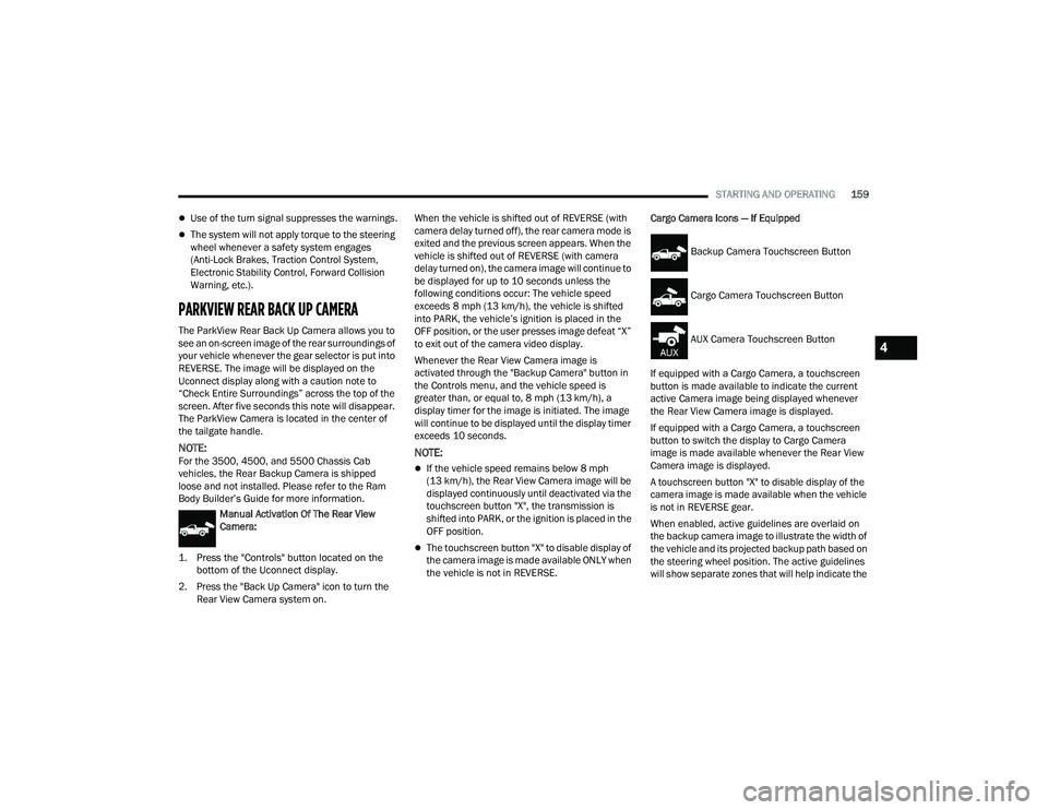
Cargo Camera Icons — If Equipped
If equipped with a Cargo Camera, a touchscreen
button is made available to indicate the current
active Camera image being displayed whenever
the Rear View Camera image is displayed.
If equipped with a Cargo Camera, a touchscreen
button to switch the display to Cargo Camera
image is made available whenever the Rear View
Camera image is displayed.
A touchscreen button "X" to disable display of the
camera image is made available when the vehicle
is not in REVERSE gear.
When enabled, active guidelines are overlaid on
the backup camera image to illustrate the width of
the vehicle and its projected backup path based on
the steering wheel position. The active guidelines
will show separate zones that will help indicate the
Backup Camera Touchscreen Button
Cargo Camera Touchscreen Button
AUX Camera Touchscreen Button
4
22_DPF_OM_EN_USC_t.book Page 159
Page 194 of 428
192MULTIMEDIA
My Profile
When the My Profile button is pressed on the touchscreen, the system displays options related to the vehicle’s profiles.
NOTE:Depending on the vehicle’s options, feature settings may vary.
Setting Name Description
Language This setting will change the language of the Uconnect system and Instrument
Cluster Display. The available languages are English, Français, and Español.
Display Mode This setting will adjust the display for the radio to “Auto” or “Manual”.
“Manual” allows for more customization with the radio display.
Display Brightness Headlights On This setting will allow you to set the brightness when the headlights are on. To
access this setting, Display Mode must be set to “Manual”. The “+” setting will
increase the brightness; the “-” will decrease the brightness.
Display Brightness Headlights Off This setting will allow you to set the brightness when the headlights are off. To
access this setting, Display Mode must be set to “Manual”. The “+” setting will
increase the brightness; the “-” will decrease the brightness.
Set Theme This setting will allow you to change the display theme.
Units The available settings are “Speed” (MPH or km/h), “Distance” (mi or km),
“Fuel Consumption” (MPG [US], MPG [UK], L/100 km, or km/L), “Pressure”
(psi, kPa, or bar), “Temperature” (°C or °F), Power” (HP [US], Gal HP [UK], or
kW), and “Torque” (lb-ft or Nm) units of measurement independently.
Touchscreen Beep This setting will allow you to turn the touchscreen beep on or off.
Show Main Category Bar Labels This setting will allow the main category bar labels to be shown on or off.
Navigation Next Turn Pop-ups Displayed in Cluster This setting will display navigation prompts in the Instrument Cluster Display.
Phone Pop-ups Displayed In Cluster This setting will display smartphone notifications and messages in the
Instrument Cluster Display.
22_DPF_OM_EN_USC_t.book Page 192
Page 197 of 428
MULTIMEDIA195
Display
When the Display button is pressed on the touchscreen, the system will display the options related to the theme (if equipped), brightness, and color of the
touchscreen. The available settings are:
NOTE:Depending on the vehicle’s options, feature settings may vary.
Setting Name Description
Language This setting will change the language of the Uconnect system and Instrument
Cluster Display. The available languages are English, Français, and Español.
Display Mode This setting will allow you to set the brightness manually or have the system
set it automatically. The “Auto” setting has the system automatically adjust
the display brightness. The “Manual” setting will allow the user to adjust the
brightness of the display.
Display Brightness With Headlights ON/Brightness This setting will allow you to set the brightness when the headlights are on. To
access this setting, Display Mode must be set to Manual. The “+” setting will
increase the brightness; the “-” will decrease the brightness.
Display Brightness With Headlights OFF/Brightness This setting will allow you to set the brightness when the headlights are off. To
access this setting, Display Mode must be set to Manual. The “+” setting will
increase the brightness; the “-” will decrease the brightness.
Set Theme This setting will allow you to change the display theme.
Units The available settings are “Speed” (MPH or km/h), “Distance” (mi or km),
“Fuel Consumption” (MPG [US], MPG [UK], L/100 km, or km/L), “Pressure”
(psi, kPa, or bar), “Temperature” (°C or °F), Power” (HP [US], Gal HP [UK], or
kW), and “Torque” (lb-ft or Nm) units of measurement independently.
Keyboard This setting will change the keyboard type on the display. The selectable
keyboards are “ABCDEF Keyboard”, “QWERTY Keyboard”, and “AZERTY
Keyboard”.
5
22_DPF_OM_EN_USC_t.book Page 195
Page 262 of 428

260SAFETY
Anti-Lock Brake System (ABS) Warning
Light
The yellow ABS Warning Light will turn on when the
ignition is placed in the ON/RUN mode and may
stay on for as long as four seconds.
If the ABS Warning Light remains on or comes on
while driving, it indicates that the anti-lock portion
of the brake system is not functioning and that
service is required. However, the conventional
brake system will continue to operate normally if
the ABS Warning Light is on.
If the ABS Warning Light is on, the brake system
should be serviced as soon as possible to restore
the benefits of anti-lock brakes. If the ABS Warning
Light does not come on when the ignition is placed
in the ON/RUN mode, have the light repaired as
soon as possible.
ELECTRONIC BRAKE CONTROL (EBC)
S
YSTEM
Your vehicle is equipped with an advanced
Electronic Brake Control (EBC) system. This system
includes Anti-Lock Brake System (ABS), Brake
Assist System (BAS), Electronic Brake Force
Distribution (EBD), Hill Start Assist (HSA),
Electronic Roll Mitigation (ERM), Electronic
Stability Control (ESC), and Traction Control
System (TCS). These systems work together to
enhance both vehicle stability and control in
various driving conditions. Your vehicle may also be equipped with Trailer
Sway Control (TSC) and Hill Descent Control (HDC).
Brake Assist System (BAS)
The BAS is designed to optimize the vehicle’s
braking capability during emergency braking
maneuvers. The system detects an emergency
braking situation by sensing the rate and amount
of brake application and then applies optimum
pressure to the brakes. This can help reduce
braking distances. The BAS complements the
Anti-Lock Brake System (ABS). Applying the brakes
very quickly results in the best BAS assistance. To
receive the benefit of the system, you must apply
continuous braking pressure during the stopping
sequence (do not “pump” the brakes). Do not
reduce brake pedal pressure unless braking is no
longer desired. Once the brake pedal is released,
the BAS is deactivated.
Brake System Warning Light
The red Brake System Warning Light will turn on
when the ignition is placed in the ON/RUN mode
and may stay on for as long as four seconds.
If the Brake System Warning Light remains on or
comes on while driving, it indicates that the brake
system is not functioning properly and that
immediate service is required. If the Brake System
Warning Light does not come on when the ignition
is placed in the ON/RUN mode, have the light
repaired as soon as possible.
Electronic Brake Force Distribution (EBD)
EBD manages the distribution of the braking
torque between the front and rear axles by limiting
braking pressure to the rear axle. This is done to
prevent overslip of the rear wheels to avoid vehicle
instability, and to prevent the rear axle from
entering ABS before the front axle.
Electronic Roll Mitigation (ERM)
ERM anticipates the potential for wheel lift by
monitoring the driver’s steering wheel input and
the speed of the vehicle. When ERM determines
that the rate of change of the steering wheel angle
and vehicle’s speed are sufficient to potentially
cause wheel lift, it then applies the appropriate
brake and may also reduce engine power to lessen
the chance that wheel lift will occur. ERM can only
reduce the chance of wheel lift occurring during
severe or evasive driving maneuvers; it cannot
WARNING!
The Brake Assist System (BAS) cannot prevent the
natural laws of physics from acting on the vehicle,
nor can it increase the traction afforded by pre
-
vailing road conditions. BAS cannot prevent colli -
sions, including those resulting from excessive
speed in turns, driving on very slippery surfaces,
or hydroplaning. The capabilities of a BAS-
equipped vehicle must never be exploited in a
reckless or dangerous manner, which could jeop -
ardize the user's safety or the safety of others.
22_DPF_OM_EN_USC_t.book Page 260
Page 264 of 428
262SAFETY
ESC Operating Modes
Depending upon model and mode of operation, the
ESC system may have multiple operating modes.
ESC On
This is the normal operating mode for the ESC
system. Whenever the vehicle is started, the ESC
system will be in this mode. This mode should be
used for most driving conditions. Alternate ESC
modes should only be used for specific reasons as
noted in the following paragraphs.
Partial Off
This mode may be useful if the vehicle becomes
stuck. This mode may modify TCS and ESC
thresholds for activation, which allows for more
wheel spin than normally allowed.
To enter the “Partial Off” mode, momentarily push
the ESC OFF button and the ESC OFF Indicator
Light will illuminate. To turn the ESC on again,
momentarily push the ESC OFF button and the ESC
OFF Indicator Light will turn off.
NOTE:For vehicles with multiple partial ESC modes, the
push and release of the button will toggle the ESC
modes. Multiple attempts may be required to
return to "ESC On" mode. Full Off — If Equipped
This mode is intended for off-highway or off-road
use only and should not be used on any public
roadways. In this mode, TCS and ESC features are
turned off. To enter the “Full Off” mode, push and
hold the ESC OFF button for five seconds while the
vehicle is stopped with the engine running. After
five seconds, a chime will sound, the ESC OFF
Indicator Light will illuminate, and the “ESC OFF”
message will display in the instrument cluster. To
turn ESC on again, momentarily push the ESC OFF
button.
NOTE:The system may switch from ESC “Full Off” to
“Partial Off” mode when the vehicle exceeds a
predetermined speed. When the vehicle speed
slows below the predetermined speed the system
will return to ESC “Full Off”.
ESC modes may also be affected by drive modes (if
equipped).WARNING!
When in “Partial Off” mode, the TCS function
-
ality of ESC, except for the limited slip feature
described in the TCS section, has been
disabled and the ESC OFF Indicator Light will
be illuminated. When in “Partial Off” mode,
the engine power reduction feature of TCS is
disabled, and the enhanced vehicle stability
offered by the ESC system is reduced.
Trailer Sway Control (TSC) is disabled when
the ESC system is in the “Partial Off” mode.
WARNING!
In the ESC “Full Off” mode, the engine torque
reduction and stability features are disabled.
Therefore, enhanced vehicle stability offered
by the ESC system is unavailable. In an emer -
gency evasive maneuver, the ESC system will
not engage to assist in maintaining stability.
ESC “Full Off” mode is intended for
off-highway or off-road use only.
The Electronic Stability Control (ESC) cannot
prevent the natural laws of physics from
acting on the vehicle, nor can it increase the
traction afforded by prevailing road condi -
tions. ESC cannot prevent all accidents,
including those resulting from excessive
speed in turns, driving on very slippery
surfaces, or hydroplaning. ESC also cannot
prevent collisions.
22_DPF_OM_EN_USC_t.book Page 262
Page 311 of 428

SAFETY309
PERIODIC SAFETY CHECKS YOU SHOULD
M
AKE OUTSIDE THE VEHICLE
Tires
Examine tires for excessive tread wear and uneven
wear patterns. Check for stones, nails, glass, or
other objects lodged in the tread or sidewall.
Inspect the tread for cuts and cracks. Inspect
sidewalls for cuts, cracks, and bulges. Check the
lug nuts/bolt torque for tightness. Check the tires
(including spare) for proper cold inflation pressure.
Lights
Have someone observe the operation of brake
lights and exterior lights while you work the
controls. Check turn signal and high beam
indicator lights on the instrument panel.
Door Latches
Check for proper closing, latching, and locking.
Fluid Leaks
Check area under the vehicle after overnight
parking for fuel, coolant, oil, or other fluid leaks.
Also, if gasoline fumes are detected or if fuel or
brake fluid leaks are suspected, the cause should
be located and corrected immediately.
EXHAUST GAS The best protection against carbon monoxide entry
into the vehicle body is a properly maintained
engine exhaust system.
Whenever a change is noticed in the sound of the
exhaust system, when exhaust fumes can be
detected inside the vehicle, or when the underside
or rear of the vehicle is damaged, have an
authorized dealer inspect the complete exhaust
system and adjacent body areas for broken,
damaged, deteriorated, or mispositioned parts.
Open seams or loose connections could permit
exhaust fumes to seep into the passenger
compartment. In addition, inspect the exhaust
system each time the vehicle is raised for
lubrication or oil change. Replace as required.
WARNING!
Exhaust gases can injure or kill. They contain
carbon monoxide (CO), which is colorless and
odorless. Breathing it can make you
unconscious and can eventually poison you. To
avoid breathing (CO), follow these safety tips:
Do not run the engine in a closed garage or in
confined areas any longer than needed to
move your vehicle in or out of the area.
If you are required to drive with the trunk/lift -
gate/rear doors open, make sure that all
windows are closed and the climate control
BLOWER switch is set at high speed. DO NOT
use the recirculation mode.
If it is necessary to sit in a parked vehicle with
the engine running, adjust your heating or
cooling controls to force outside air into the
vehicle. Set the blower at high speed.
6
22_DPF_OM_EN_USC_t.book Page 309
Page 319 of 428

IN CASE OF EMERGENCY317
Jack Warning Label
1. If equipped, remove the spare wheel and tools from storage.
2. Using the lug wrench, loosen, but do not remove, the lug nuts by turning them counter -
clockwise one turn while the wheel is still on
the ground.
3. When changing the front wheel, place the jack under the axle as close to the tire as possible.
Front Jacking Locations
When changing a rear wheel, securely place
the jack under the sway bar bracket (unless
both tires are flat on one side, then place jack
under shock bracket) facing forward in vehicle.
Rear Jacking Location
Before raising the wheel off the ground, make
sure that the jack will not damage surrounding
truck parts and adjust the jack position as re
-
quired.
4. Raise the vehicle until the wheel just clears the surface.
5. Remove the lug nuts and pull the wheel off. For Single Rear-Wheel (SRW) models, Install the
spare wheel and lug nuts with the cone shaped
end of the nuts toward the wheel. For Dual
Rear-Wheel (DRW) models, the lug nuts are a
two-piece assembly with a flat face. Lightly
tighten the nuts. To avoid risk of forcing the
vehicle off the jack, do not fully tighten the
nuts until the vehicle has been lowered.
6. Using the lug wrench, finish tightening the nuts using a crisscross pattern Ú page 397. If in
doubt about the correct tightness, have them
checked with a torque wrench by an
authorized dealer or at a service station.
CAUTION!
Do not attempt to raise the vehicle by jacking on
locations other than those indicated in the
Jacking Instructions for this vehicle.
WARNING!
Raising the vehicle higher than necessary can
make the vehicle less stable. It could slip off the
jack and hurt someone near it. Raise the vehicle
only enough to remove the tire.
7
22_DPF_OM_EN_USC_t.book Page 317