torque RAM CHASSIS CAB 2023 User Guide
[x] Cancel search | Manufacturer: RAM, Model Year: 2023, Model line: CHASSIS CAB, Model: RAM CHASSIS CAB 2023Pages: 444, PDF Size: 20.51 MB
Page 166 of 444

164STARTING AND OPERATING
warning in the form of torque applied to the
steering wheel, as well as a visual warning in the
instrument cluster display to prompt the driver to
remain within the lane boundaries.
The driver may manually override the haptic
warning by applying torque to the steering wheel at
any time.
When only a single lane marking is detected and
the driver drifts across that lane marking (no turn
signal applied), the LaneSense system provides a
visual warning through the instrument cluster
display to prompt the driver to remain within the
lane.
When only a single lane marking is detected, a
haptic (torque) warning will not be provided.
NOTE:When operating conditions have been met, the
LaneSense system will monitor if the driver’s
hands are on the steering wheel and provide an
audible and visual warning to the driver if removed.
The system will cancel if the driver does not return
their hands to the wheel.
TURNING LANESENSE ON OR OFF
The LaneSense button is located on the
switch panel below the Uconnect display.
NOTE:If your vehicle is equipped with a 12–inch
Uconnect Display screen, the LaneSense button is
located above the display.
To turn the LaneSense system on, push the
LaneSense button (LED turns off). A “LaneSense
On” message is shown in the instrument cluster
display.
To turn the LaneSense system off, push the
LaneSense button again (LED turns on).
NOTE:The LaneSense system will retain the last system
state (on or off) from the last ignition cycle when
the ignition is changed to the ON/RUN position.
LANESENSE WARNING MESSAGE
The LaneSense system will indicate the current
lane drift condition through the instrument cluster
display.
When the LaneSense system is on, the lane lines
are gray when both of the lane boundaries have
not been detected and the LaneSense telltale
is solid white.
System ON (Gray Lines) With White Telltale
Left Lane Departure — Only Left Lane Detected
When the LaneSense system is on, the
LaneSense Telltale is solid white when only
the left lane marking has been detected and the
system is ready to provide visual warnings in the
instrument cluster display if an unintentional
lane departure occurs on the left side.
When the LaneSense system senses the lane
has been approached and is in a lane departure
situation, the visual warning in the instrument
cluster display will show the left lane line
flashing yellow (on/off). The LaneSense telltale
changes from solid white to flashing yellow.
23_DPF_OM_EN_USC_t.book Page 164
Page 167 of 444

STARTING AND OPERATING165
Lane Crossed (Flashing Yellow Lane Line) With Yellow Telltale
NOTE:The LaneSense system operates with similar
behavior for a right lane departure when only the
right lane marking has been detected.
Left Lane Departure — Both Lane Lines Detected
When the LaneSense system is on, and both the
lane markings have been detected, the system
is ready to provide visual warnings in the instru-
ment cluster display and a torque warning in the
steering wheel if an unintentional lane depar -
ture occurs. The lane lines turn from gray to
white and the LaneSense telltale is solid
green.
Lanes Sensed (White Lines) With Green Telltale
When the LaneSense system senses a lane drift
situation, the left lane line turns solid yellow.
The LaneSense telltale changes from solid
green to solid yellow. At this time torque is
applied to the steering wheel in the opposite
direction of the lane boundary.
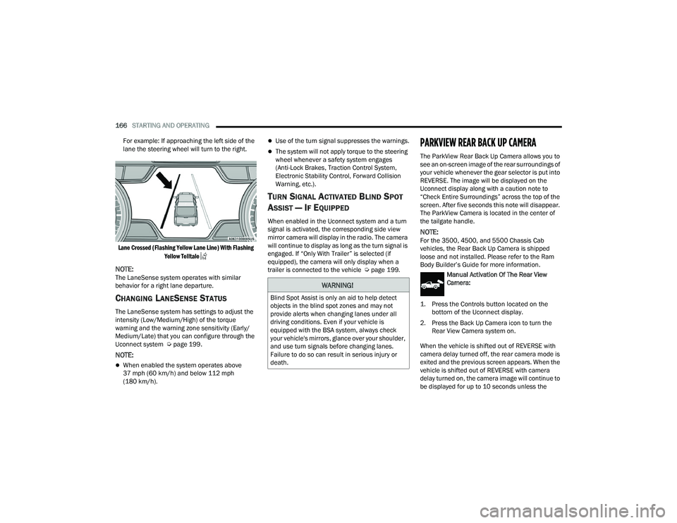
For example: If approaching the left side of the
lane the steering wheel will turn to the right.
Lane Approached (Solid Yellow Lane Line) With Solid
Yellow Telltale
When the LaneSense system senses the lane
has been approached and is in a lane departure
situation, the left lane line flashes yellow (on/
off). The LaneSense telltale changes from
solid yellow to flashing yellow. At this time
torque is applied to the steering wheel in the
opposite direction of the lane boundary.
4
23_DPF_OM_EN_USC_t.book Page 165
Page 168 of 444
166STARTING AND OPERATING
For example: If approaching the left side of the
lane the steering wheel will turn to the right.
Lane Crossed (Flashing Yellow Lane Line) With Flashing Yellow Telltale
NOTE:The LaneSense system operates with similar
behavior for a right lane departure.
CHANGING LANESENSE STATUS
The LaneSense system has settings to adjust the
intensity (Low/Medium/High) of the torque
warning and the warning zone sensitivity (Early/
Medium/Late) that you can configure through the
Uconnect system Ú page 199.
NOTE:
When enabled the system operates above
37 mph (60 km/h) and below 112 mph
(180 km/h).
Use of the turn signal suppresses the warnings.
The system will not apply torque to the steering
wheel whenever a safety system engages
(Anti-Lock Brakes, Traction Control System,
Electronic Stability Control, Forward Collision
Warning, etc.).
TURN SIGNAL ACTIVATED BLIND SPOT
A
SSIST — IF EQUIPPED
When enabled in the Uconnect system and a turn
signal is activated, the corresponding side view
mirror camera will display in the radio. The camera
will continue to display as long as the turn signal is
engaged. If “Only With Trailer” is selected (if
equipped), the camera will only display when a
trailer is connected to the vehicle Ú page 199.
PARKVIEW REAR BACK UP CAMERA
The ParkView Rear Back Up Camera allows you to
see an on-screen image of the rear surroundings of
your vehicle whenever the gear selector is put into
REVERSE. The image will be displayed on the
Uconnect display along with a caution note to
“Check Entire Surroundings” across the top of the
screen. After five seconds this note will disappear.
The ParkView Camera is located in the center of
the tailgate handle.
NOTE:For the 3500, 4500, and 5500 Chassis Cab
vehicles, the Rear Back Up Camera is shipped
loose and not installed. Please refer to the Ram
Body Builder’s Guide for more information.
Manual Activation Of The Rear View
Camera:
1. Press the Controls button located on the bottom of the Uconnect display.
2. Press the Back Up Camera icon to turn the Rear View Camera system on.
When the vehicle is shifted out of REVERSE with
camera delay turned off, the rear camera mode is
exited and the previous screen appears. When the
vehicle is shifted out of REVERSE with camera
delay turned on, the camera image will continue to
be displayed for up to 10 seconds unless the
WARNING!
Blind Spot Assist is only an aid to help detect
objects in the blind spot zones and may not
provide alerts when changing lanes under all
driving conditions. Even if your vehicle is
equipped with the BSA system, always check
your vehicle's mirrors, glance over your shoulder,
and use turn signals before changing lanes.
Failure to do so can result in serious injury or
death.
23_DPF_OM_EN_USC_t.book Page 166
Page 203 of 444
MULTIMEDIA201
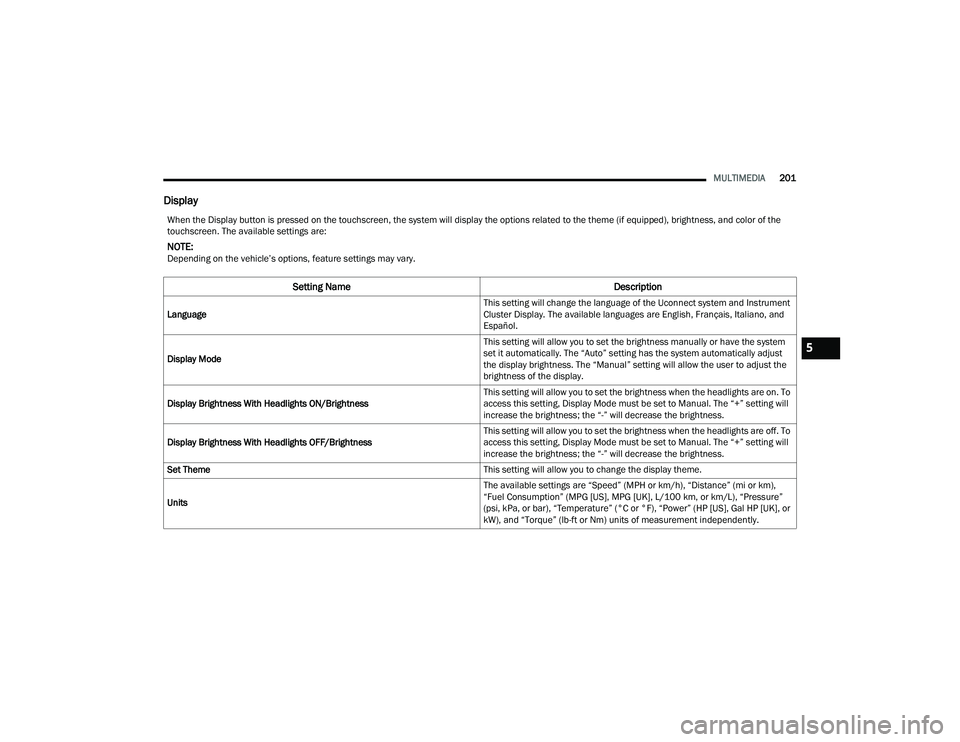
Display
When the Display button is pressed on the touchscreen, the system will display the options related to the theme (if equipped), brightness, and color of the
touchscreen. The available settings are:
NOTE:Depending on the vehicle’s options, feature settings may vary.
Setting Name Description
Language This setting will change the language of the Uconnect system and Instrument
Cluster Display. The available languages are English, Français, Italiano, and
Español.
Display Mode This setting will allow you to set the brightness manually or have the system
set it automatically. The “Auto” setting has the system automatically adjust
the display brightness. The “Manual” setting will allow the user to adjust the
brightness of the display.
Display Brightness With Headlights ON/Brightness This setting will allow you to set the brightness when the headlights are on. To
access this setting, Display Mode must be set to Manual. The “+” setting will
increase the brightness; the “-” will decrease the brightness.
Display Brightness With Headlights OFF/Brightness This setting will allow you to set the brightness when the headlights are off. To
access this setting, Display Mode must be set to Manual. The “+” setting will
increase the brightness; the “-” will decrease the brightness.
Set Theme This setting will allow you to change the display theme.
Units The available settings are “Speed” (MPH or km/h), “Distance” (mi or km),
“Fuel Consumption” (MPG [US], MPG [UK], L/100 km, or km/L), “Pressure”
(psi, kPa, or bar), “Temperature” (°C or °F), “Power” (HP [US], Gal HP [UK], or
kW), and “Torque” (lb-ft or Nm) units of measurement independently.
5
23_DPF_OM_EN_USC_t.book Page 201
Page 205 of 444
MULTIMEDIA203
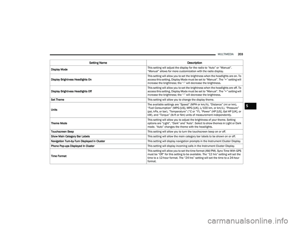
Display Mode This setting will adjust the display for the radio to “Auto” or “Manual”.
“Manual” allows for more customization with the radio display.
Display Brightness Headlights On This setting will allow you to set the brightness when the headlights are on. To
access this setting, Display Mode must be set to “Manual”. The “+” setting will
increase the brightness; the “-” will decrease the brightness.
Display Brightness Headlights Off This setting will allow you to set the brightness when the headlights are off. To
access this setting, Display Mode must be set to “Manual”. The “+” setting will
increase the brightness; the “-” will decrease the brightness.
Set Theme This setting will allow you to change the display theme.
Units The available settings are “Speed” (MPH or km/h), “Distance” (mi or km),
“Fuel Consumption” (MPG [US], MPG [UK], L/100 km, or km/L), “Pressure”
(psi, kPa, or bar), “Temperature” (°C or °F), “Power” (HP [US], Gal HP [UK], or
kW), and “Torque” (lb-ft or Nm) units of measurement independently.
Theme Mode This setting will allow you to adjust the brightness of your theme. Setting
options are “Light”, “Dark” and “Auto”. Select to show themes in Light or Dark
mode. “Auto” changes the theme with the headlights.
Touchscreen Beep This setting will allow you to turn the touchscreen beep on or off.
Show Main Category Bar Labels This setting will allow the main category bar labels to be shown on or off.
Navigation Turn-by-Turn Displayed in Cluster This setting will display navigation prompts in the Instrument Cluster Display.
Phone Pop-ups Displayed In Cluster This setting will display incoming calls in the Instrument Cluster Display.
Time Format This setting will allow you to set the time format (AM/PM). Sync Time With GPS
must be “Off” for this setting to be available. The “12 hrs” setting will set the
time to a 12-hour format. The “24 hrs” setting will set the time to a 24-hour
format.
Setting Name
Description
5
23_DPF_OM_EN_USC_t.book Page 203
Page 274 of 444
272SAFETY
Brake System Warning Light
The red Brake System Warning Light will turn on
when the ignition is placed in the ON/RUN mode
and may stay on for as long as four seconds.
If the Brake System Warning Light remains on or
comes on while driving, it indicates that the brake
system is not functioning properly and that
immediate service is required. If the Brake System
Warning Light does not come on when the ignition
is placed in the ON/RUN mode, have the light
repaired as soon as possible.
Electronic Brake Force Distribution (EBD)
EBD manages the distribution of the braking
torque between the front and rear axles by limiting
braking pressure to the rear axle. This is done to
prevent overslip of the rear wheels to avoid vehicle
instability, and to prevent the rear axle from
entering ABS before the front axle.
Electronic Roll Mitigation (ERM)
ERM anticipates the potential for wheel lift by
monitoring the driver’s steering wheel input and
the speed of the vehicle. When ERM determines
that the rate of change of the steering wheel angle
and vehicle’s speed are sufficient to potentially
cause wheel lift, it then applies the appropriate
brake and may also reduce engine power to lessen
the chance that wheel lift will occur. ERM can only
reduce the chance of wheel lift occurring during
severe or evasive driving maneuvers; it cannot prevent wheel lift due to other factors, such as
road conditions, leaving the roadway, or striking
objects or other vehicles.
NOTE:ERM is disabled any time the ESC is in “Full Off”
mode (if equipped). For a complete explanation of
the available ESC modes, see Ú
page 272.
Electronic Stability Control (ESC)
ESC enhances directional control and stability of
the vehicle under various driving conditions. ESC
corrects for oversteering or understeering of the
vehicle by applying the brake of the appropriate
wheel(s) to counteract the above conditions.
Engine power may also be reduced to help the
vehicle maintain the desired path.
Oversteer — when the vehicle is turning more
than appropriate for the steering wheel position.
Understeer — when the vehicle is turning less
than appropriate for the steering wheel position.
ESC uses sensors in the vehicle to determine the
vehicle path intended by the driver and compares
it to the actual path of the vehicle. When the actual
path does not match the intended path, ESC
applies the brake of the appropriate wheel to
assist in counteracting the oversteer or understeer
condition.
The ESC Activation/Malfunction Indicator Light
located in the instrument cluster will start to flash
as soon as the ESC system becomes active. The
ESC Activation/Malfunction Indicator Light also
flashes when the TCS is active. If the ESC
Activation/Malfunction Indicator Light begins to
flash during acceleration, ease up on the
accelerator and apply as little throttle as possible.
Be sure to adapt your speed and driving to the
prevailing road conditions.
WARNING!
Many factors, such as vehicle loading, road
conditions and driving conditions, influence the
chance that wheel lift or rollover may occur. ERM
cannot prevent all wheel lift or rollovers,
especially those that involve leaving the roadway
or striking objects or other vehicles. The
capabilities of an ERM-equipped vehicle must
never be exploited in a reckless or dangerous
manner which could jeopardize the user's safety
or the safety of others.
23_DPF_OM_EN_USC_t.book Page 272
Page 276 of 444
274SAFETY
(Continued)
Full Off — If Equipped
This mode is intended for off-highway or off-road use
only and should not be used on any public roadways.
In this mode, TCS and ESC features are turned off.
To enter the “Full Off” mode, push and hold the ESC
OFF button for five seconds while the vehicle is
stopped with the engine running. After five seconds,
a chime will sound, the ESC OFF Indicator Light will
illuminate, and the “ESC OFF” message will display
in the instrument cluster. To turn ESC on again,
momentarily push the ESC OFF button.
NOTE:The system may switch from ESC “Full Off” to
“Partial Off” mode when the vehicle exceeds a
predetermined speed. When the vehicle speed
slows below the predetermined speed the system
will return to ESC “Full Off”.
ESC modes may also be affected by drive modes (if
equipped).ESC Activation/Malfunction Indicator Light
And ESC OFF Indicator Light
The ESC Activation/Malfunction Indicator
Light in the instrument cluster will come
on when the ignition is placed in the ON
mode. It should go out with the engine
running. If the ESC Activation/Malfunction
Indicator Light comes on continuously with the
engine running, a malfunction has been detected
in the ESC system. If this light remains on after
several ignition cycles, and the vehicle has been
driven several miles (kilometers) at speeds greater
than 30 mph (48 km/h), see an authorized dealer
as soon as possible to have the problem
diagnosed and corrected.
The ESC Activation/Malfunction Indicator Light
starts to flash as soon as the tires lose traction and
the ESC system becomes active. The ESC Activation/Malfunction Indicator Light also flashes
when TCS is active. If the ESC Activation/
Malfunction Indicator Light begins to flash during
acceleration, ease up on the accelerator and apply
as little throttle as possible. Be sure to adapt your
speed and driving to the prevailing road conditions.
The ESC OFF Indicator Light indicates
that the Electronic Stability Control (ESC)
is in a reduced mode.
NOTE:
The ESC Activation/Malfunction Indicator Light
and the ESC OFF Indicator Light come on
momentarily each time the ignition is placed in
the ON position.
Each time the ignition is placed in the ON posi -
tion, the ESC system will be on even if it was
turned off previously.
The ESC system will make buzzing or clicking
sounds when it is active. This is normal; the
sounds will stop when ESC becomes inactive
following the maneuver that caused the ESC
activation.
Hill Descent Control (HDC) — If Equipped
HDC is intended for low speed off-road driving
while in 4WD Low. HDC maintains vehicle speed
while descending hills during various driving
situations. HDC controls vehicle speed by actively
controlling the brakes.
WARNING!
In the ESC “Full Off” mode, the engine torque
reduction and stability features are disabled.
Therefore, enhanced vehicle stability offered
by the ESC system is unavailable. In an emer -
gency evasive maneuver, the ESC system will
not engage to assist in maintaining stability.
ESC “Full Off” mode is intended for
off-highway or off-road use only.
The Electronic Stability Control (ESC) cannot
prevent the natural laws of physics from
acting on the vehicle, nor can it increase the
traction afforded by prevailing road condi -
tions. ESC cannot prevent all accidents,
including those resulting from excessive
speed in turns, driving on very slippery
surfaces, or hydroplaning. ESC also cannot
prevent collisions.
WARNING!
23_DPF_OM_EN_USC_t.book Page 274
Page 325 of 444

SAFETY323
(Continued)
(Continued)
PERIODIC SAFETY CHECKS YOU SHOULD
M
AKE OUTSIDE THE VEHICLE
Tires
Examine tires for excessive tread wear and uneven
wear patterns. Check for stones, nails, glass, or
other objects lodged in the tread or sidewall.
Inspect the tread for cuts and cracks. Inspect
sidewalls for cuts, cracks, and bulges. Check the
lug nuts/bolt torque for tightness. Check the tires
(including spare) for proper cold inflation pressure.
WARNING!
An improperly attached, damaged, folded, or
stacked floor mat, or damaged floor mat
fasteners may cause your floor mat to interfere
with the accelerator, brake, or clutch pedals and
cause a loss of vehicle control. To prevent
SERIOUS INJURY or DEATH:
ALWAYS securely attach your floor
mat using the floor mat fasteners. DO
NOT install your floor mat upside down
or turn your floor mat over. Lightly pull
to confirm mat is secured using the floor mat
fasteners on a regular basis.
ALWAYS REMOVE THE EXISTING
FLOOR MAT FROM THE VEHICLE
before installing any other floor mat.
NEVER install or stack an additional
floor mat on top of an existing floor mat.
ONLY install floor mats designed to fit your
vehicle. NEVER install a floor mat that cannot
be properly attached and secured to your
vehicle. If a floor mat needs to be replaced,
only use a FCA approved floor mat for the
specific make, model, and year of your
vehicle.
ONLY use the driver’s side floor mat on the
driver’s side floor area. To check for interfer -
ence, with the vehicle properly parked with the
engine off, fully depress the accelerator, the
brake, and the clutch pedal (if present) to
check for interference. If your floor mat inter -
feres with the operation of any pedal, or is not
secure to the floor, remove the floor mat from
the vehicle and place the floor mat in your
trunk.
ONLY use the passenger’s side floor mat on
the passenger’s side floor area.
ALWAYS make sure objects cannot fall or slide
into the driver’s side floor area when the
vehicle is moving. Objects can become
trapped under accelerator, brake, or clutch
pedals and could cause a loss of vehicle
control.
NEVER place any objects under the floor mat
(e.g., towels, keys, etc.). These objects could
change the position of the floor mat and may
cause interference with the accelerator,
brake, or clutch pedals.
WARNING!
If the vehicle carpet has been removed and
re-installed, always properly attach carpet to
the floor and check the floor mat fasteners are
secure to the vehicle carpet. Fully depress
each pedal to check for interference with the
accelerator, brake, or clutch pedals then
re-install the floor mats.
It is recommended to only use mild soap and
water to clean your floor mats. After cleaning,
always check your floor mat has been properly
installed and is secured to your vehicle using
the floor mat fasteners by lightly pulling mat.
WARNING!
6
23_DPF_OM_EN_USC_t.book Page 323
Page 333 of 444

IN CASE OF EMERGENCY331
1. If equipped, remove the spare wheel and tools from storage.
2. Using the lug wrench, loosen, but do not remove, the lug nuts by turning them counter -
clockwise one turn while the wheel is still on
the ground.
3. When changing the front wheel, place the jack under the axle as close to the tire as possible.
Front Jacking Locations
When changing a rear wheel, securely place
the jack under the sway bar bracket (unless
both tires are flat on one side, then place jack
under shock bracket) facing forward in vehicle.
Rear Jacking Location
Before raising the wheel off the ground, make
sure that the jack will not damage surrounding
truck parts and adjust the jack position as re -
quired.
4. Raise the vehicle until the wheel just clears the surface.
5. Remove the lug nuts and pull the wheel off. For Single Rear-Wheel (SRW) models, Install the
spare wheel and lug nuts with the cone shaped
end of the nuts toward the wheel. For Dual
Rear-Wheel (DRW) models, the lug nuts are a two-piece assembly with a flat face. Lightly
tighten the nuts. To avoid risk of forcing the
vehicle off the jack, do not fully tighten the
nuts until the vehicle has been lowered.
6. Using the lug wrench, finish tightening the nuts using a crisscross pattern Ú page 411. If in
doubt about the correct tightness, have them
checked with a torque wrench by an
authorized dealer or at a service station.
7. Install wheel center cap (if equipped) and remove wheel blocks. Do not install chrome or
aluminum wheel center caps on the spare
wheel. This may result in cap damage.
8. Lower the jack to its fully closed position. Stow the replaced tire and tools as previously
described.
9. Adjust the tire pressure when possible.
10. After 25 miles (40 km), check the lug nut torque Ú page 411 with a torque wrench to
ensure that all lug nuts are properly seated
against the wheel.
WARNING!
Raising the vehicle higher than necessary can
make the vehicle less stable. It could slip off the
jack and hurt someone near it. Raise the vehicle
only enough to remove the tire.
WARNING!
A loose tire or jack thrown forward in a collision
or hard stop, could endanger the occupants of
the vehicle. Always stow the jack parts and the
spare tire in the places provided.
7
23_DPF_OM_EN_USC_t.book Page 331
Page 334 of 444

332IN CASE OF EMERGENCY
Dual Rear Wheels
Slots in the wheels will assist in properly orienting
the inner and outer wheels. Align these slots when
assembling the wheels for best access to the tire
valve on the inner wheel. The tires of both dual
wheels must be completely off the ground when
tightening to ensure wheel centering and
maximum wheel clamping.
Dual wheel models require a special heavy-duty lug
nut tightening adapter (included with the vehicle)
to correctly tighten the lug nuts. Also, when it is
necessary to remove and install dual rear wheels,
use a proper vehicle lifting device.
NOTE:When installing a spare tire (if equipped) as part of
a dual rear wheel end combination, the tire
diameter of the two individual tires must be
compared. If there is a significant difference, the
larger tire should be installed in a front location.
The correct direction of rotation for dual tire instal -
lations must also be observed.
It is recommended that wheel stud nuts be kept
torqued to specifications at all times. Torque wheel
stud nuts to specifications at each lubrication
interval Ú page 411.
Wheel Nuts
All wheel nuts should be tightened occasionally to
eliminate the possibility of wheel studs being
sheared or the bolt holes in the wheels becoming elongated. This is especially important during the
first few hundred miles/kilometers of operation to
allow the wheel nuts to become properly set. All
wheel nuts should first be firmly seated against the
wheel. The wheel nuts should then be tightened to
recommended torque. Tighten the wheel nuts to
final torque in increments. Progress around the
bolt circle, tightening the wheel nut opposite to the
wheel nut just previously tightened until final
torque is achieved Ú
page 411.
TO STOW THE FLAT OR SPARE —
I
F EQUIPPED
Refer to Upfitters Body Builder’s Guide for
information on stowing your spare tire (if
equipped).
HUB CAPS/WHEEL COVERS —
I
F EQUIPPED
The hub caps must be removed before raising the
vehicle off the ground. For 3500 Single Rear-Wheel (SRW) models, use
the flat end of the lug wrench to hook and pull off
the hub cap. Find the opening in the hub cap,
insert the lug wrench, and pull off the cap. If you
need to pry against the wheel, protect the wheel
surface.
Lug Wrench Insertion Location — Hub Cap
On 3500 models with Dual Rear-Wheels (DRW),
you must first remove the hub caps—use the
procedure noted for the single rear wheel. For the
wheel covers (wheel skins), insert the flat end of
the lug wrench between the outer edge of the
wheel cover and the wheel. Pry against the wheel
to remove the wheel cover. Repeat this procedure
around the wheel until the cover pops off.
CAUTION!
Use extreme caution when removing the front
and rear wheel covers. Damage can occur to the
center cap and/or the wheel if screwdriver type
tools are used. A pulling motion, not a pry off
motion, is recommended to remove the caps.
23_DPF_OM_EN_USC_t.book Page 332