lock RAM CHASSIS CAB 2023 Owner's Manual
[x] Cancel search | Manufacturer: RAM, Model Year: 2023, Model line: CHASSIS CAB, Model: RAM CHASSIS CAB 2023Pages: 444, PDF Size: 20.51 MB
Page 33 of 444
GETTING TO KNOW YOUR VEHICLE31
LINKING AND UNLINKING THE REMOTE
K
EYLESS ENTRY KEY FOB TO MEMORY
Your key fob can be programmed to recall one of
two saved memory profiles.
NOTE:Before programming your key fob you must select
the “Personal Settings Linked to Key Fob” feature
through the Uconnect Settings Ú page 199.
To program your key fob, perform the following:
1. Place the vehicle’s ignition in the OFF position.
2. Select a desired memory profile 1 or 2.
3. Once the profile has been recalled, push and release the set (S) button on the memory
switch.
4. Push and release button (1) or (2) accordingly. “Memory Profile Set” (1 or 2) will display in the
instrument cluster.
5. Push and release the lock button on the key fob within 10 seconds.
NOTE:Your key fob can be unlinked from your memory
settings by pushing the set (S) button, and within
10 seconds, pushing the unlock button on the key
fob.
MEMORY POSITION RECALL
NOTE:The vehicle speed must be lower than 5 mph
(8 km/h) to recall memory positions. If a recall is
attempted when the vehicle speed is greater than
5 mph (8 km/h), a message will be displayed in the
instrument cluster display.
To recall the memory settings for driver one or two,
push the desired memory button number (1 or 2)
or the unlock button on the key fob linked to the
desired memory position.
A recall can be canceled by pushing any of the
memory buttons during a recall (S, 1, or 2). When
a recall is canceled, the driver's seat and the
adjustable pedals (if equipped) stop moving. A
delay of one second will occur before another
recall can be selected.
SEATS
Seats are a part of the Occupant Restraint system
of the vehicle.
WARNING!
It is dangerous to ride in a cargo area, inside
or outside of a vehicle. In a collision, people
riding in these areas are more likely to be seri -
ously injured or killed.
Do not allow people to ride in any area of your
vehicle that is not equipped with seats and
seat belts. In a collision, people riding in these
areas are more likely to be seriously injured or
killed.
Be sure everyone in your vehicle is in a seat
and using a seat belt properly.
2
23_DPF_OM_EN_USC_t.book Page 31
Page 38 of 444

36GETTING TO KNOW YOUR VEHICLE
NOTE:The engine must be running for the ventilated
seats to operate.
For information on use with the Remote Start
system, see Úpage 21.
HEAD RESTRAINTS
Head restraints are designed to reduce the risk of
injury by restricting head movement in the event of
a rear impact. Head restraints should be adjusted
so that the top of the head restraint is located
above the top of your ear.
NOTE:Do not reverse the head restraints (making the
rear of the head restraint face forward) in an
attempt to gain additional clearance to the back of
your head.
Front Head Restraints
Four-Way Head Restraints — If Equipped
Your vehicle may be equipped with front four-way
driver and passenger head restraints.
To raise the head restraint, pull upward on the
head restraint. To lower the head restraint, push
the adjustment button, located at the base of the
head restraint, and push downward on the head
restraint.
To adjust the head restraint forward, pull the top of
the head restraint toward the front of the vehicle
as desired and release. To adjust the head
restraint rearward, pull the top of the head
restraint to the forward most position and release.
The head restraint will return to the rear most
position.
Forward Adjustment
NOTE:Four-way head restraints have seven tilt/locking
positions. When pulling fully forward, the head
restraint will spring back to the untilted, rearward
most position when released.
Two-Way Head Restraints — If Equipped
Your vehicle may be equipped with front two-way
driver and passenger head restraints.
To raise the head restraint, pull upward on the
head restraint. To lower the head restraint, push
the adjustment button, located at the base of head
restraint, and push downward on the head
restraint.
Head Restraint Adjustment Button Location
NOTE:If your vehicle is equipped with a front bench seat,
the center head restraint is not adjustable or
removable.
WARNING!
All occupants, including the driver, should not
operate a vehicle or sit in a vehicle’s seat until
the head restraints are placed in their proper
positions in order to minimize the risk of neck
injury in the event of a crash.
Head restraints should never be adjusted
while the vehicle is in motion. Driving a vehicle
with the head restraints improperly adjusted
or removed could cause serious injury or
death in the event of a collision.
23_DPF_OM_EN_USC_t.book Page 36
Page 40 of 444

38GETTING TO KNOW YOUR VEHICLE
Rear Head Restraint Removal
To remove the head restraint, push the adjustment
button and the release button while pulling upward
on the whole assembly. To reinstall the head
restraint, put the head restraint posts into the
holes and adjust it to the appropriate height.
NOTE:To remove outboard restraints, the rear seat
bottom must be folded up.
DRIVER ADJUSTABLE PEDALS —
IF EQUIPPED
The adjustable pedals system is designed to allow
a greater range of driver comfort for steering wheel
tilt and seat position. This feature allows the brake
and accelerator pedals to move toward or away
from the driver to provide improved position with
the steering wheel.
The adjustable pedal switch is located to the left
side of the steering column.
Adjustable Pedals Switch
The pedals can be adjusted with the ignition in the
OFF position.
The pedals
cannot be adjusted when the vehicle is
in REVERSE or when the Cruise Control system is
on. If there is an attempt to adjust the pedals when
the system is locked out, the following messages
will appear (on vehicles equipped with an
instrument cluster display):
Adjustable Pedal Disabled — Cruise Control
Engaged
Adjustable Pedal Disabled — Vehicle In Reverse
NOTE:
Always adjust the pedals to a position that
allows full movement of the pedal.
Further small adjustments may be necessary to
find the best possible seat/pedal position.
For vehicles equipped with Driver Memory
Settings, you can use your remote keyless entry
key fob or the memory switch on the driver’s
door trim panel to return the adjustable pedals
to saved positions Ú page 30.
WARNING!
A loose head restraint thrown forward in a
collision or hard stop could cause serious
injury or death to occupants of the vehicle.
Always securely stow removed head restraints
in a location outside the occupant compart -
ment.
ALL the head restraints MUST be reinstalled in
the vehicle to properly protect the occupants.
Follow the reinstallation instructions prior to
operating the vehicle or occupying a seat.
WARNING!
Do not adjust the pedals while the vehicle is
moving. You could lose control and have an
accident. Always adjust the pedals while the
vehicle is parked.
23_DPF_OM_EN_USC_t.book Page 38
Page 42 of 444
40GETTING TO KNOW YOUR VEHICLE
When Digital Rearview Mode is not in use, push the
on/off control lever forward toward the windshield
to return the mirror to the regular Automatic
Dimming Mirror.
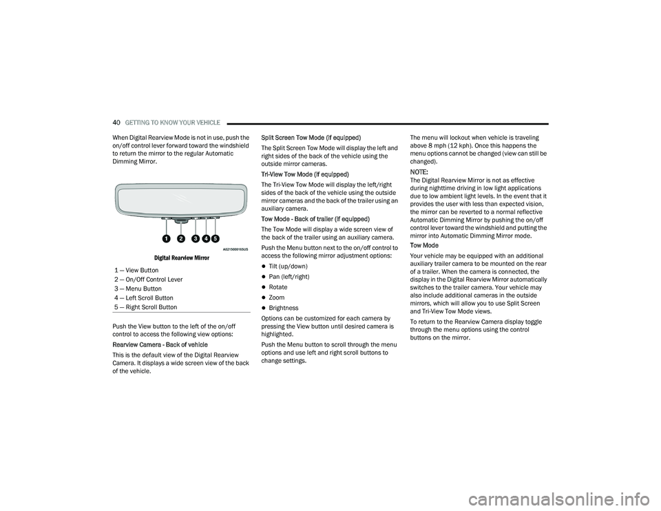
Digital Rearview Mirror
Push the View button to the left of the on/off
control to access the following view options:
Rearview Camera - Back of vehicle
This is the default view of the Digital Rearview
Camera. It displays a wide screen view of the back
of the vehicle. Split Screen Tow Mode (if equipped)
The Split Screen Tow Mode will display the left and
right sides of the back of the vehicle using the
outside mirror cameras.
Tri-View Tow Mode (if equipped)
The Tri-View Tow Mode will display the left/right
sides of the back of the vehicle using the outside
mirror cameras and the back of the trailer using an
auxiliary camera.
Tow Mode - Back of trailer (if equipped)
The Tow Mode will display a wide screen view of
the back of the trailer using an auxiliary camera.
Push the Menu button next to the on/off control to
access the following mirror adjustment options:
Tilt (up/down)
Pan (left/right)
Rotate
Zoom
Brightness
Options can be customized for each camera by
pressing the View button until desired camera is
highlighted.
Push the Menu button to scroll through the menu
options and use left and right scroll buttons to
change settings. The menu will lockout when vehicle is traveling
above 8 mph (12 kph). Once this happens the
menu options cannot be changed (view can still be
changed).
NOTE:The Digital Rearview Mirror is not as effective
during nighttime driving in low light applications
due to low ambient light levels. In the event that it
provides the user with less than expected vision,
the mirror can be reverted to a normal reflective
Automatic Dimming Mirror by pushing the on/off
control lever toward the windshield and putting the
mirror into Automatic Dimming Mirror mode.
Tow Mode
Your vehicle may be equipped with an additional
auxiliary trailer camera to be mounted on the rear
of a trailer. When the camera is connected, the
display in the Digital Rearview Mirror automatically
switches to the trailer camera. Your vehicle may
also include additional cameras in the outside
mirrors, which will allow you to use Split Screen
and Tri-View Tow Mode views.
To return to the Rearview Camera display toggle
through the menu options using the control
buttons on the mirror.
1 — View Button
2 — On/Off Control Lever
3 — Menu Button
4 — Left Scroll Button
5 — Right Scroll Button
23_DPF_OM_EN_USC_t.book Page 40
Page 43 of 444
GETTING TO KNOW YOUR VEHICLE41
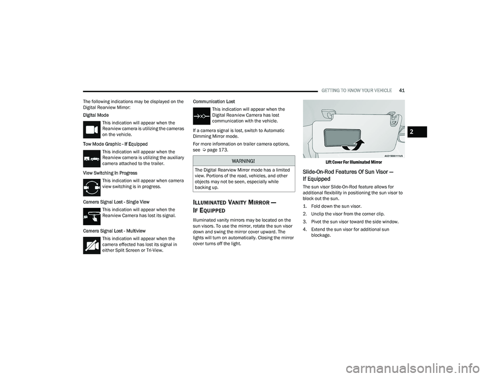
The following indications may be displayed on the
Digital Rearview Mirror:
Digital Mode This indication will appear when the
Rearview camera is utilizing the cameras
on the vehicle.
Tow Mode Graphic - If Equipped This indication will appear when the
Rearview camera is utilizing the auxiliary
camera attached to the trailer.
View Switching In Progress This indication will appear when camera
view switching is in progress.
Camera Signal Lost - Single View This indication will appear when the
Rearview Camera has lost its signal.
Camera Signal Lost - Multiview This indication will appear when the
camera effected has lost its signal in
either Split Screen or Tri-View. Communication Lost
This indication will appear when the
Digital Rearview Camera has lost
communication with the vehicle.
If a camera signal is lost, switch to Automatic
Dimming Mirror mode.
For more information on trailer camera options,
see Ú page 173.
ILLUMINATED VANITY MIRROR —
I
F EQUIPPED
Illuminated vanity mirrors may be located on the
sun visors. To use the mirror, rotate the sun visor
down and swing the mirror cover upward. The
lights will turn on automatically. Closing the mirror
cover turns off the light.
Lift Cover For Illuminated Mirror
Slide-On-Rod Features Of Sun Visor —
If Equipped
The sun visor Slide-On-Rod feature allows for
additional flexibility in positioning the sun visor to
block out the sun.
1. Fold down the sun visor.
2. Unclip the visor from the corner clip.
3. Pivot the sun visor toward the side window.
4. Extend the sun visor for additional sun
blockage.
WARNING!
The Digital Rearview Mirror mode has a limited
view. Portions of the road, vehicles, and other
objects may not be seen, especially while
backing up.
2
23_DPF_OM_EN_USC_t.book Page 41
Page 44 of 444
42GETTING TO KNOW YOUR VEHICLE
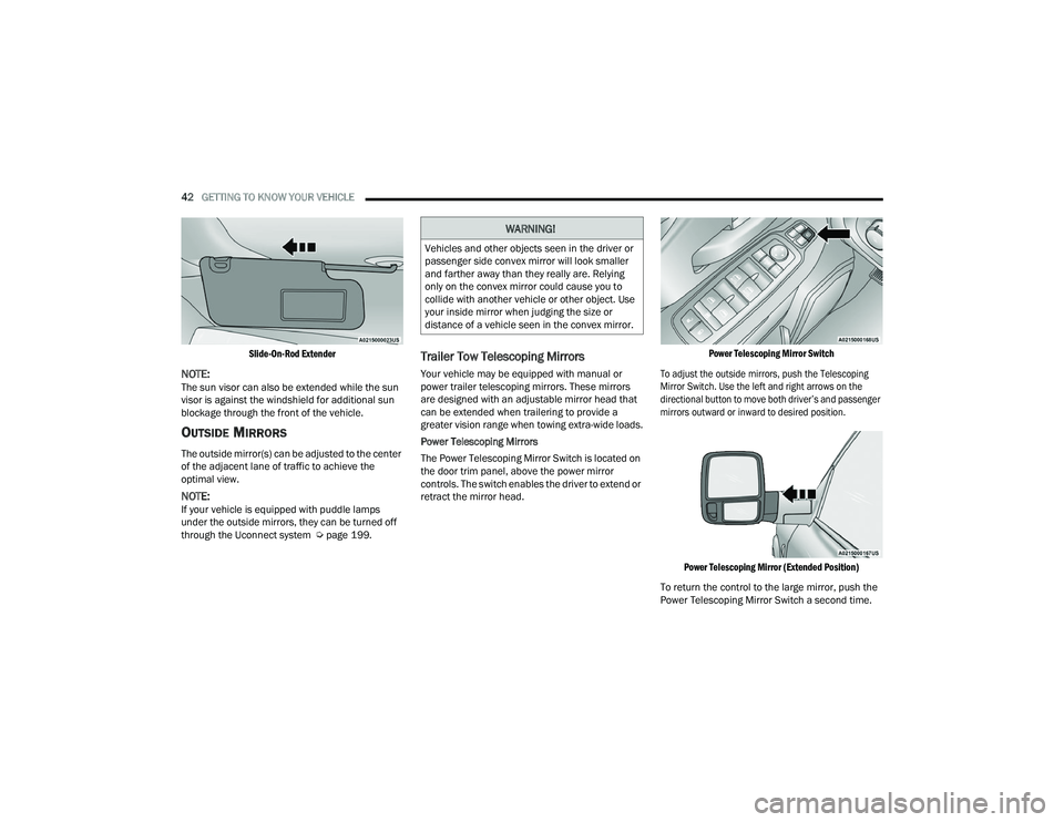
Slide-On-Rod Extender
NOTE:The sun visor can also be extended while the sun
visor is against the windshield for additional sun
blockage through the front of the vehicle.
OUTSIDE MIRRORS
The outside mirror(s) can be adjusted to the center
of the adjacent lane of traffic to achieve the
optimal view.
NOTE:If your vehicle is equipped with puddle lamps
under the outside mirrors, they can be turned off
through the Uconnect system Ú page 199.
Trailer Tow Telescoping Mirrors
Your vehicle may be equipped with manual or
power trailer telescoping mirrors. These mirrors
are designed with an adjustable mirror head that
can be extended when trailering to provide a
greater vision range when towing extra-wide loads.
Power Telescoping Mirrors
The Power Telescoping Mirror Switch is located on
the door trim panel, above the power mirror
controls. The switch enables the driver to extend or
retract the mirror head.
Power Telescoping Mirror Switch
To adjust the outside mirrors, push the Telescoping
Mirror Switch. Use the left and right arrows on the
directional button to move both driver’s and passenger
mirrors outward or inward to desired position.
Power Telescoping Mirror (Extended Position)
To return the control to the large mirror, push the
Power Telescoping Mirror Switch a second time.
WARNING!
Vehicles and other objects seen in the driver or
passenger side convex mirror will look smaller
and farther away than they really are. Relying
only on the convex mirror could cause you to
collide with another vehicle or other object. Use
your inside mirror when judging the size or
distance of a vehicle seen in the convex mirror.
23_DPF_OM_EN_USC_t.book Page 42
Page 46 of 444
44GETTING TO KNOW YOUR VEHICLE
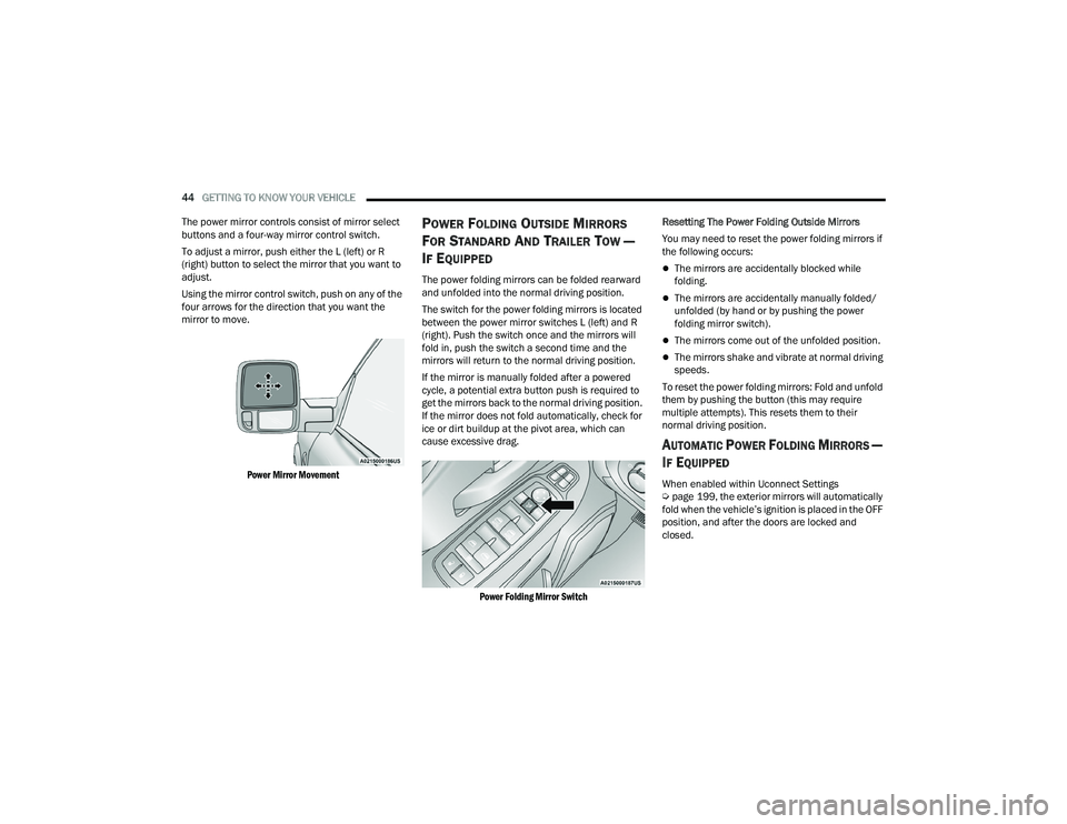
The power mirror controls consist of mirror select
buttons and a four-way mirror control switch.
To adjust a mirror, push either the L (left) or R
(right) button to select the mirror that you want to
adjust.
Using the mirror control switch, push on any of the
four arrows for the direction that you want the
mirror to move.
Power Mirror Movement
POWER FOLDING OUTSIDE MIRRORS
F
OR STANDARD AND TRAILER TOW —
I
F EQUIPPED
The power folding mirrors can be folded rearward
and unfolded into the normal driving position.
The switch for the power folding mirrors is located
between the power mirror switches L (left) and R
(right). Push the switch once and the mirrors will
fold in, push the switch a second time and the
mirrors will return to the normal driving position.
If the mirror is manually folded after a powered
cycle, a potential extra button push is required to
get the mirrors back to the normal driving position.
If the mirror does not fold automatically, check for
ice or dirt buildup at the pivot area, which can
cause excessive drag.
Power Folding Mirror Switch
Resetting The Power Folding Outside Mirrors
You may need to reset the power folding mirrors if
the following occurs:The mirrors are accidentally blocked while
folding.
The mirrors are accidentally manually folded/
unfolded (by hand or by pushing the power
folding mirror switch).
The mirrors come out of the unfolded position.
The mirrors shake and vibrate at normal driving
speeds.
To reset the power folding mirrors: Fold and unfold
them by pushing the button (this may require
multiple attempts). This resets them to their
normal driving position.
AUTOMATIC POWER FOLDING MIRRORS —
I
F EQUIPPED
When enabled within Uconnect Settings
Ú page 199, the exterior mirrors will automatically
fold when the vehicle’s ignition is placed in the OFF
position, and after the doors are locked and
closed.
23_DPF_OM_EN_USC_t.book Page 44
Page 47 of 444
GETTING TO KNOW YOUR VEHICLE45
The exterior mirrors will auto-fold in the following
situations after the ignition is placed in the OFF
position:
Pushing the lock button on the door panel
before the door is opened.
NOTE:If the doors are already locked, push the lock
button again.
Opening the door, then pushing the lock button
on the door panel, followed by closing the door.
After exiting the vehicle, close the doors then
push the lock button on the key fob.
After exiting the vehicle, close the doors then
touch the lock icon on the Passive Entry door
handle.
If the exterior mirrors were folded automatically,
they will unfold when the ignition is placed in the
ON/RUN position.
NOTE:If the mirrors were folded manually, by using the
power folding mirror switch on the driver’s door
panel, they will not automatically unfold.
POWER CONVEX MIRROR SWITCH —
I
F EQUIPPED
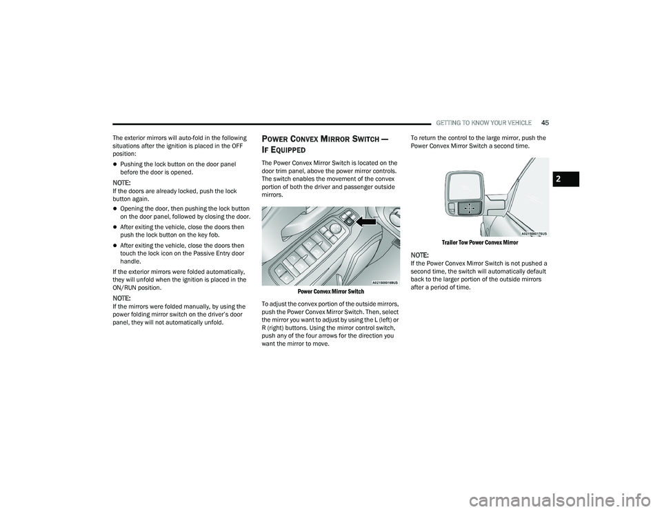
The Power Convex Mirror Switch is located on the
door trim panel, above the power mirror controls.
The switch enables the movement of the convex
portion of both the driver and passenger outside
mirrors.
Power Convex Mirror Switch
To adjust the convex portion of the outside mirrors,
push the Power Convex Mirror Switch. Then, select
the mirror you want to adjust by using the L (left) or
R (right) buttons. Using the mirror control switch,
push any of the four arrows for the direction you
want the mirror to move. To return the control to the large mirror, push the
Power Convex Mirror Switch a second time.
Trailer Tow Power Convex Mirror
NOTE:If the Power Convex Mirror Switch is not pushed a
second time, the switch will automatically default
back to the larger portion of the outside mirrors
after a period of time.
2
23_DPF_OM_EN_USC_t.book Page 45
Page 53 of 444

GETTING TO KNOW YOUR VEHICLE51
EXTERIOR LIGHTS
HEADLIGHT SWITCH
The headlight switch is located on the left side of
the instrument panel. This switch controls the
operation of the headlights, parking lights,
automatic headlights (if equipped), instrument
panel light dimming, cargo light/rear guidance
lights (if equipped), and fog lights (if equipped).
Headlight Switch Headlight Switch (Vehicles Sold In Canada)
NOTE:Vehicles sold in Canada are equipped with a head
-
light switch with an AUTO and ON detent but
without an OFF detent. Headlights will be deacti -
vated when the headlight switch is placed in the
parking lights position. However, the Daytime
Running Lights (DRLs) will be activated along with
the front and rear marker lights. The DRLs may be
deactivated when the parking brake is engaged. To turn on the headlights, rotate the headlight
switch clockwise. When the headlight switch is on,
the parking lights, taillights, license plate light and
instrument panel lights are also turned on. To turn
off the headlights, rotate the headlight switch back
to the O (off) position.
NOTE:For vehicles sold in Canada, rotate the headlight
switch clockwise from the parking lights and
instrument panel lights position to the first detent
to turn on headlights, parking lights, and
instrument panel lights. Rotate the headlight
switch to the second detent for the AUTO position.
MULTIFUNCTION LEVER
The multifunction lever is located on the left side of
the steering column.
Multifunction Lever
1 — Rotate Headlight Control
2 — Push Fog Light Switch
3 — Ambient Light Dimmer Control
4 — Instrument Panel Dimmer Control
5 — Push Cargo Light Switch
1 — Rotate Headlight Control
2 — Push Fog Light Switch
3 — Ambient Light Dimmer Control
4 — Instrument Panel Dimmer Control
5 — Push Cargo Light Switch
2
23_DPF_OM_EN_USC_t.book Page 51
Page 55 of 444
GETTING TO KNOW YOUR VEHICLE53
DIRECTIONAL LED HEADLAMP SYSTEM —
I
F EQUIPPED
This is a system consisting of LED (low/high beam)
headlights that incorporate dynamic cornering with
5-degree inboard/15-degree outboard swivel. The
headlights continuously and automatically adapt
to the driving conditions around bends or when
cornering based on steering wheel angle.
The system directs the headlights to light up the
road in the best way, taking into account the speed
of the vehicle and the bend or corner angle, as well
as the speed of the vehicle while the steering
wheel is being turned.
The adaptive lights are automatically activated
when the vehicle is traveling above approximately
5 mph (8 km/h).
This system can be turned on/off through the
Uconnect Settings under “Steering Directed
Lights” Ú page 199.
PARKING LIGHTS
To turn on the parking lights and instrument panel
lights, rotate the headlight switch clockwise. To
turn off the parking lights, rotate the headlight
switch back to the O (off) position.
NOTE:Vehicles sold in Canada are equipped with a head -
light switch with an AUTO and ON detent but without an OFF detent. Headlights will be deacti-
vated when the headlight switch is placed in the
parking lights position. However, the Daytime
Running Lights (DRLs) will be activated along with
the front and rear marker lights. The DRLs may be
deactivated when the parking brake is engaged.
HEADLIGHTS ON WITH WIPERS
If your vehicle is equipped with Automatic
Headlights, it also has this
customer-programmable feature. When your
headlights are in the automatic mode and the
engine is running, they will automatically turn on
when the wiper system is on. This feature is
programmable through the Uconnect system
Ú
page 199.
If your vehicle is equipped with the Rain Sensing
Wiper system Ú page 58, and it is activated, the
headlights will automatically turn on after the
wipers complete five wipe cycles within
approximately one minute. They will turn off
approximately four minutes after the wipers
completely stop.
NOTE:When your headlights come on during the daytime,
the instrument panel lights will automatically dim
to the lower nighttime intensity.
HEADLIGHT ILLUMINATION ON
A
PPROACH
When enabled, the headlights, exterior door
handle pocket lights (if equipped), and interior
lights will illuminate when the unlock button on the
key fob is pushed as the operator is approaching
the vehicle. This feature can be turned on/off, and
the length of time the headlights stay on can be
programmed for up to 90 seconds within Uconnect
Settings Ú page 199.
HEADLIGHT DELAY
To assist when exiting the vehicle, the headlight
delay feature will leave the headlights on for up to
90 seconds. This delay is initiated when the
ignition is placed in the OFF position while the
headlight switch is on, and then the headlight
switch is cycled off. Headlight delay can be
canceled by either turning the headlight switch on
then off, or by placing the ignition in the ON
position.
NOTE:
This feature can be programmed through the
Uconnect system Ú page 199.
The headlight delay feature is automatically
activated if the headlight switch is left in the
AUTO position when the ignition is placed in the
OFF position.
2
23_DPF_OM_EN_USC_t.book Page 53