tow RAM CHASSIS CAB 2023 Owner's Manual
[x] Cancel search | Manufacturer: RAM, Model Year: 2023, Model line: CHASSIS CAB, Model: RAM CHASSIS CAB 2023Pages: 444, PDF Size: 20.51 MB
Page 71 of 444

GETTING TO KNOW YOUR VEHICLE69
Unfolding The Load Floor/Crew Cab
1. Lift the 60/40 seat cushion(s) to the upward position.
Load Floor Legs In Stowed Position
2. Unfold both the legs using the straps.
Load Floor Legs In Opened Position
3. Lift the front panel until the load floor unfolds
into position.
Load Floor In Open Position
4. Reverse the procedure to store the load floor.
Positioning The Load Floor For Storage Access
Under The Seat
1. Lift the 60/40 seat cushion(s) to the upward position.
2. Unsnap the securing snap located at either side of the load floor.
3. Lift the load floor up to access storage under the load floor.
Load Floor Securing Straps/Crew Cab
4. Reverse the procedure to put the load floor back in the secured down position before you
operate the vehicle.
WARNING!
Do not drive with the load floor in the up
position. When stopping fast or in an accident,
the load floor could move to the down position
causing serious injury.
2
23_DPF_OM_EN_USC_t.book Page 69
Page 74 of 444
72GETTING TO KNOW YOUR VEHICLE
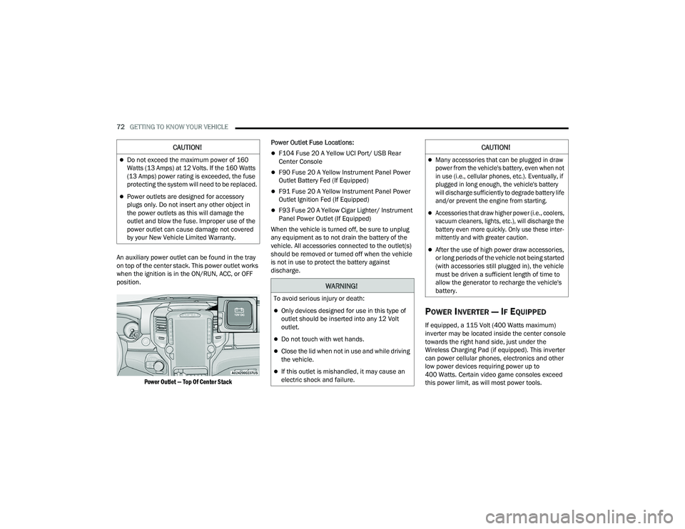
An auxiliary power outlet can be found in the tray
on top of the center stack. This power outlet works
when the ignition is in the ON/RUN, ACC, or OFF
position.
Power Outlet — Top Of Center Stack
Power Outlet Fuse Locations:
F104 Fuse 20 A Yellow UCI Port/ USB Rear
Center Console
F90 Fuse 20 A Yellow Instrument Panel Power
Outlet Battery Fed (If Equipped)
F91 Fuse 20 A Yellow Instrument Panel Power
Outlet Ignition Fed (If Equipped)
F93 Fuse 20 A Yellow Cigar Lighter/ Instrument
Panel Power Outlet (If Equipped)
When the vehicle is turned off, be sure to unplug
any equipment as to not drain the battery of the
vehicle. All accessories connected to the outlet(s)
should be removed or turned off when the vehicle
is not in use to protect the battery against
discharge.
POWER INVERTER — IF EQUIPPED
If equipped, a 115 Volt (400 Watts maximum)
inverter may be located inside the center console
towards the right hand side, just under the
Wireless Charging Pad (if equipped). This inverter
can power cellular phones, electronics and other
low power devices requiring power up to
400 Watts. Certain video game consoles exceed
this power limit, as will most power tools.
CAUTION!
Do not exceed the maximum power of 160
Watts (13 Amps) at 12 Volts. If the 160 Watts
(13 Amps) power rating is exceeded, the fuse
protecting the system will need to be replaced.
Power outlets are designed for accessory
plugs only. Do not insert any other object in
the power outlets as this will damage the
outlet and blow the fuse. Improper use of the
power outlet can cause damage not covered
by your New Vehicle Limited Warranty.
WARNING!
To avoid serious injury or death:
Only devices designed for use in this type of
outlet should be inserted into any 12 Volt
outlet.
Do not touch with wet hands.
Close the lid when not in use and while driving
the vehicle.
If this outlet is mishandled, it may cause an
electric shock and failure.
CAUTION!
Many accessories that can be plugged in draw
power from the vehicle's battery, even when not
in use (i.e., cellular phones, etc.). Eventually, if
plugged in long enough, the vehicle's battery
will discharge sufficiently to degrade battery life
and/or prevent the engine from starting.
Accessories that draw higher power (i.e., coolers,
vacuum cleaners, lights, etc.), will discharge the
battery even more quickly. Only use these inter -
mittently and with greater caution.
After the use of high power draw accessories,
or long periods of the vehicle not being started
(with accessories still plugged in), the vehicle
must be driven a sufficient length of time to
allow the generator to recharge the vehicle's
battery.
23_DPF_OM_EN_USC_t.book Page 72
Page 81 of 444
GETTING TO KNOW YOUR INSTRUMENT PANEL79
Use this QR code to access your
digital experience.
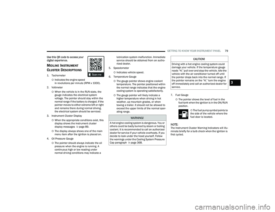
MIDLINE INSTRUMENT
C
LUSTER DESCRIPTIONS
1. Tachometer
Indicates the engine speed
in revolutions per minute (RPM x 1000).
2. Voltmeter
When the vehicle is in the RUN state, the
gauge indicates the electrical system
voltage. The pointer should stay within the
normal range if the battery is charged. If the
pointer moves to either extreme left or right
and remains there during normal driving,
the electrical system should be serviced.
3. Instrument Cluster Display
When the appropriate conditions exist, this
display shows the instrument cluster
display messages Ú page 89.
The display always shows one of the main
menu item after the ignition is placed on.
4. Oil Pressure Gauge
The pointer should always indicate the oil
pressure when the engine is running. A
continuous high or low reading under
normal driving conditions may indicate a lubrication system malfunction. Immediate
service should be obtained from an autho
-
rized dealer.
5. Speedometer
Indicates vehicle speed.
6. Temperature Gauge
The gauge pointer shows engine coolant
temperature. The pointer positioned within
the normal range indicates that the engine
cooling system is operating satisfactorily.
The gauge pointer will likely indicate a
higher temperature when driving in hot
weather, up mountain grades, or when
towing a trailer. It should not be allowed to
exceed the upper limits of the normal oper -
ating range. 7. Fuel Gauge
The pointer shows the level of fuel in the
fuel tank when the ignition is in the ON/RUN
position.
The fuel pump symbol points to
the side of the vehicle where the
fuel door is located.
NOTE:The Instrument Cluster Warning Indicators will illu -
minate briefly for a bulb check when the ignition is
first cycled.
WARNING!
A hot engine cooling system is dangerous. You or
others could be badly burned by steam or boiling
coolant. It is recommended to call an authorized
dealer for service if your vehicle overheats. If you
decide to look under the hood yourself, Follow
the warnings under the Cooling System Pressure
Cap paragraph Ú page 368.
CAUTION!
Driving with a hot engine cooling system could
damage your vehicle. If the temperature gauge
reads “H,” pull over and stop the vehicle. Idle the
vehicle with the air conditioner turned off until
the pointer drops back into the normal range. If
the pointer remains on the “H,” turn the engine
off immediately and call an authorized dealer for
service.
3
23_DPF_OM_EN_USC_t.book Page 79
Page 83 of 444
GETTING TO KNOW YOUR INSTRUMENT PANEL81
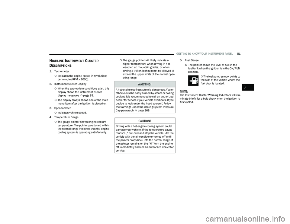
HIGHLINE INSTRUMENT CLUSTER
D
ESCRIPTIONS
1. Tachometer
Indicates the engine speed in revolutions
per minute (RPM x 1000).
2. Instrument Cluster Display
When the appropriate conditions exist, this
display shows the instrument cluster
display messages Ú page 89.
The display always shows one of the main
menu item after the ignition is placed on.
3. Speedometer
Indicates vehicle speed.
4. Temperature Gauge
The gauge pointer shows engine coolant
temperature. The pointer positioned within
the normal range indicates that the engine
cooling system is operating satisfactorily.
The gauge pointer will likely indicate a
higher temperature when driving in hot
weather, up mountain grades, or when
towing a trailer. It should not be allowed to
exceed the upper limits of the normal oper -
ating range. 5. Fuel Gauge
The pointer shows the level of fuel in the
fuel tank when the ignition is in the ON/RUN
position.
The fuel pump symbol points to
the side of the vehicle where the
fuel door is located.
NOTE:The Instrument Cluster Warning Indicators will illu -
minate briefly for a bulb check when the ignition is
first cycled.
WARNING!
A hot engine cooling system is dangerous. You or
others could be badly burned by steam or boiling
coolant. It is recommended to call an authorized
dealer for service if your vehicle overheats. If you
decide to look under the hood yourself, Follow
the warnings under the Cooling System Pressure
Cap paragraph Ú page 368.
CAUTION!
Driving with a hot engine cooling system could
damage your vehicle. If the temperature gauge
reads “H,” pull over and stop the vehicle. Idle the
vehicle with the air conditioner turned off until
the pointer drops back into the normal range. If
the pointer remains on the “H,” turn the engine
off immediately and call an authorized dealer for
service.
3
23_DPF_OM_EN_USC_t.book Page 81
Page 85 of 444
GETTING TO KNOW YOUR INSTRUMENT PANEL83
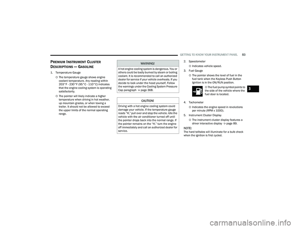
PREMIUM INSTRUMENT CLUSTER
D
ESCRIPTIONS — GASOLINE
1. Temperature Gauge
The temperature gauge shows engine
coolant temperature. Any reading within
203°F - 230°F (95°C - 110°C) indicates
that the engine cooling system is operating
satisfactorily.
The pointer will likely indicate a higher
temperature when driving in hot weather,
up mountain grades, or when towing a
trailer. It should not be allowed to exceed
the upper limits of the normal operating
range. 2. Speedometer
Indicates vehicle speed.
3. Fuel Gauge
The pointer shows the level of fuel in the
fuel tank when the Keyless Push Button
Ignition is in the ON/RUN position.
The fuel pump symbol points to
the side of the vehicle where the
fuel door is located.
4. Tachometer
Indicates the engine speed in revolutions
per minute (RPM x 1000).
5. Instrument Cluster Display
The instrument cluster display features a
driver interactive display Ú page 89.
NOTE:The hard telltales will illuminate for a bulb check
when the ignition is first cycled.
WARNING!
A hot engine cooling system is dangerous. You or
others could be badly burned by steam or boiling
coolant. It is recommended to call an authorized
dealer for service if your vehicle overheats. If you
decide to look under the hood yourself, Follow
the warnings under the Cooling System Pressure
Cap paragraph Úpage 368.
CAUTION!
Driving with a hot engine cooling system could
damage your vehicle. If the temperature gauge
reads “H,” pull over and stop the vehicle. Idle the
vehicle with the air conditioner turned off until
the pointer drops back into the normal range. If
the pointer remains on the “H,” turn the engine
off immediately and call an authorized dealer for
service.
3
23_DPF_OM_EN_USC_t.book Page 83
Page 91 of 444
GETTING TO KNOW YOUR INSTRUMENT PANEL89
PREMIUM INSTRUMENT CLUSTER
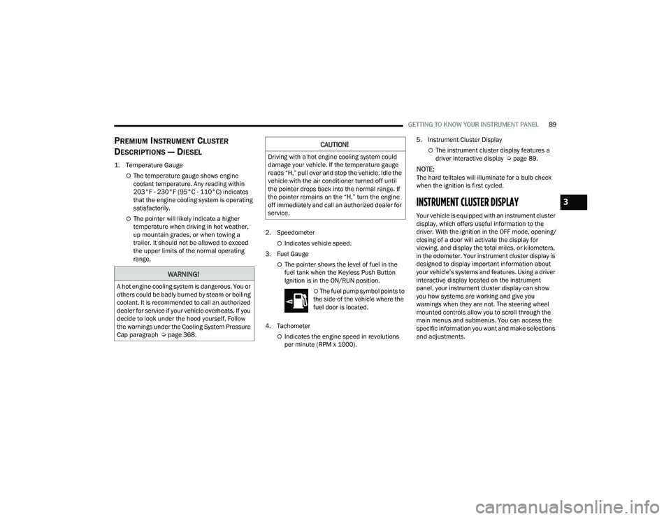
D
ESCRIPTIONS — DIESEL
1. Temperature Gauge
The temperature gauge shows engine
coolant temperature. Any reading within
203°F - 230°F (95°C - 110°C) indicates
that the engine cooling system is operating
satisfactorily.
The pointer will likely indicate a higher
temperature when driving in hot weather,
up mountain grades, or when towing a
trailer. It should not be allowed to exceed
the upper limits of the normal operating
range. 2. Speedometer
Indicates vehicle speed.
3. Fuel Gauge
The pointer shows the level of fuel in the
fuel tank when the Keyless Push Button
Ignition is in the ON/RUN position.
The fuel pump symbol points to
the side of the vehicle where the
fuel door is located.
4. Tachometer
Indicates the engine speed in revolutions
per minute (RPM x 1000). 5. Instrument Cluster Display
The instrument cluster display features a
driver interactive display Ú
page 89.
NOTE:The hard telltales will illuminate for a bulb check
when the ignition is first cycled.
INSTRUMENT CLUSTER DISPLAY
Your vehicle is equipped with an instrument cluster
display, which offers useful information to the
driver. With the ignition in the OFF mode, opening/
closing of a door will activate the display for
viewing, and display the total miles, or kilometers,
in the odometer. Your instrument cluster display is
designed to display important information about
your vehicle’s systems and features. Using a driver
interactive display located on the instrument
panel, your instrument cluster display can show
you how systems are working and give you
warnings when they are not. The steering wheel
mounted controls allow you to scroll through the
main menus and submenus. You can access the
specific information you want and make selections
and adjustments.
WARNING!
A hot engine cooling system is dangerous. You or
others could be badly burned by steam or boiling
coolant. It is recommended to call an authorized
dealer for service if your vehicle overheats. If you
decide to look under the hood yourself, Follow
the warnings under the Cooling System Pressure
Cap paragraph Úpage 368.
CAUTION!
Driving with a hot engine cooling system could
damage your vehicle. If the temperature gauge
reads “H,” pull over and stop the vehicle. Idle the
vehicle with the air conditioner turned off until
the pointer drops back into the normal range. If
the pointer remains on the “H,” turn the engine
off immediately and call an authorized dealer for
service.
3
23_DPF_OM_EN_USC_t.book Page 89
Page 94 of 444
92GETTING TO KNOW YOUR INSTRUMENT PANEL
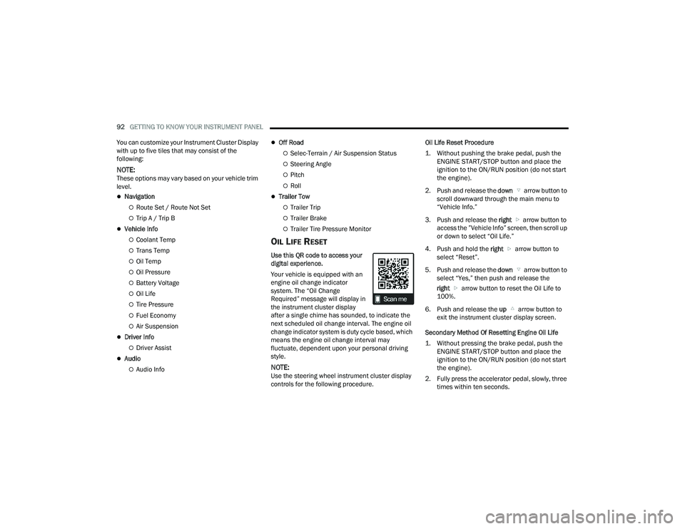
You can customize your Instrument Cluster Display
with up to five tiles that may consist of the
following:
NOTE:These options may vary based on your vehicle trim
level.
Navigation
Route Set / Route Not Set
Trip A / Trip B
Vehicle Info
Coolant Temp
Trans Temp
Oil Temp
Oil Pressure
Battery Voltage
Oil Life
Tire Pressure
Fuel Economy
Air Suspension
Driver Info
Driver Assist
Audio
Audio Info
Off Road
Selec-Terrain / Air Suspension Status
Steering Angle
Pitch
Roll
Trailer Tow
Trailer Trip
Trailer Brake
Trailer Tire Pressure Monitor
OIL LIFE RESET
Use this QR code to access your
digital experience.
Your vehicle is equipped with an
engine oil change indicator
system. The “Oil Change
Required” message will display in
the instrument cluster display
after a single chime has sounded, to indicate the
next scheduled oil change interval. The engine oil
change indicator system is duty cycle based, which
means the engine oil change interval may
fluctuate, dependent upon your personal driving
style.
NOTE:Use the steering wheel instrument cluster display
controls for the following procedure. Oil Life Reset Procedure
1. Without pushing the brake pedal, push the
ENGINE START/STOP button and place the
ignition to the ON/RUN position (do not start
the engine).
2. Push and release the down arrow button to
scroll downward through the main menu to
“Vehicle Info.”
3. Push and release the right arrow button to
access the ”Vehicle Info” screen, then scroll up
or down to select “Oil Life.”
4. Push and hold the right arrow button to
select “Reset”.
5. Push and release the down arrow button to
select “Yes,” then push and release the
right arrow button to reset the Oil Life to
100%.
6. Push and release the up arrow button to
exit the instrument cluster display screen.
Secondary Method Of Resetting Engine Oil Life
1. Without pressing the brake pedal, push the ENGINE START/STOP button and place the
ignition to the ON/RUN position (do not start
the engine).
2. Fully press the accelerator pedal, slowly, three times within ten seconds.
23_DPF_OM_EN_USC_t.book Page 92
Page 95 of 444
GETTING TO KNOW YOUR INSTRUMENT PANEL93
3. Without pushing the brake pedal, push the ENGINE START/STOP button once to return the
ignition to the OFF position.
NOTE:If the indicator message illuminates when you start
the vehicle, the oil change indicator system did not
reset. If necessary, repeat this procedure.
DISPLAY MENU ITEMS
Push and release the up or down arrow
button until the desired selectable menu icon is
highlighted in the instrument cluster display.
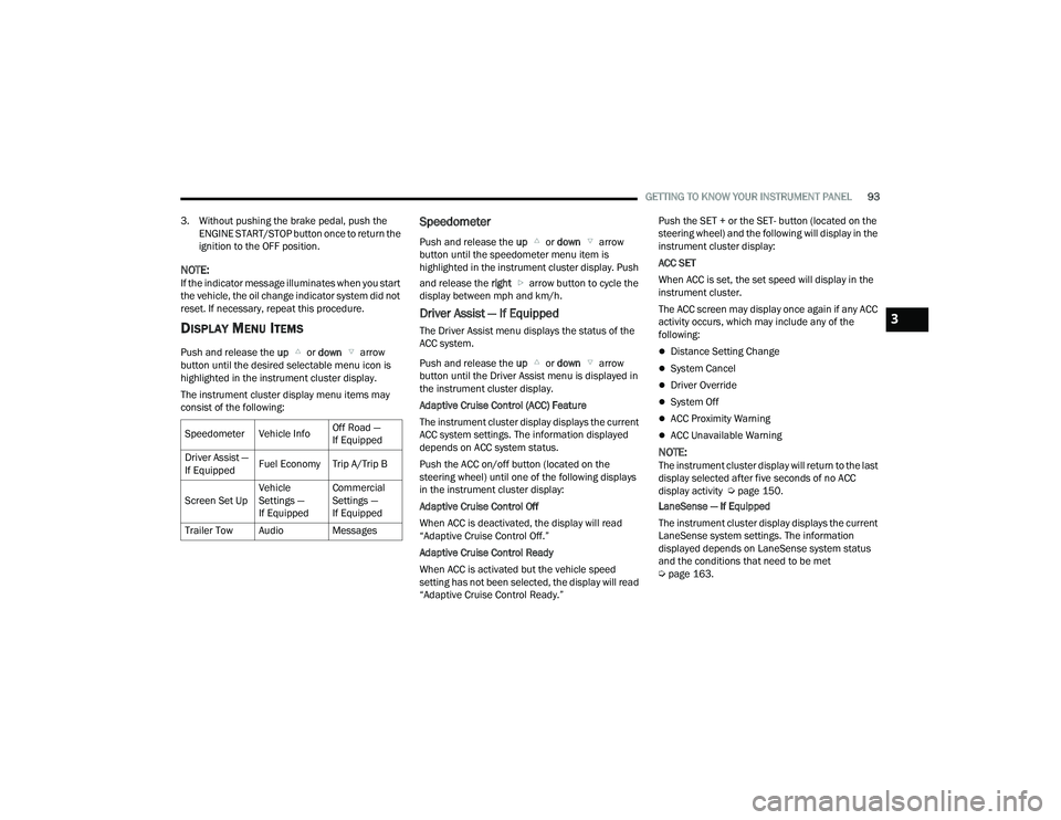
The instrument cluster display menu items may
consist of the following:
Speedometer
Push and release the up or down arrow
button until the speedometer menu item is
highlighted in the instrument cluster display. Push
and release the right arrow button to cycle the
display between mph and km/h.
Driver Assist — If Equipped
The Driver Assist menu displays the status of the
ACC system.
Push and release the up or down arrow
button until the Driver Assist menu is displayed in
the instrument cluster display.
Adaptive Cruise Control (ACC) Feature
The instrument cluster display displays the current
ACC system settings. The information displayed
depends on ACC system status.
Push the ACC on/off button (located on the
steering wheel) until one of the following displays
in the instrument cluster display:
Adaptive Cruise Control Off
When ACC is deactivated, the display will read
“Adaptive Cruise Control Off.”
Adaptive Cruise Control Ready
When ACC is activated but the vehicle speed
setting has not been selected, the display will read
“Adaptive Cruise Control Ready.” Push the SET + or the SET- button (located on the
steering wheel) and the following will display in the
instrument cluster display:
ACC SET
When ACC is set, the set speed will display in the
instrument cluster.
The ACC screen may display once again if any ACC
activity occurs, which may include any of the
following:
Distance Setting Change
System Cancel
Driver Override
System Off
ACC Proximity Warning
ACC Unavailable Warning
NOTE:The instrument cluster display will return to the last
display selected after five seconds of no ACC
display activity Ú
page 150.
LaneSense — If Equipped
The instrument cluster display displays the current
LaneSense system settings. The information
displayed depends on LaneSense system status
and the conditions that need to be met
Ú page 163.
Speedometer Vehicle Info
Off Road —
If Equipped
Driver Assist —
If Equipped Fuel Economy Trip A/Trip B
Screen Set Up Vehicle
Settings —
If EquippedCommercial
Settings —
If Equipped
Trailer Tow Audio Messages
3
23_DPF_OM_EN_USC_t.book Page 93
Page 97 of 444
GETTING TO KNOW YOUR INSTRUMENT PANEL95
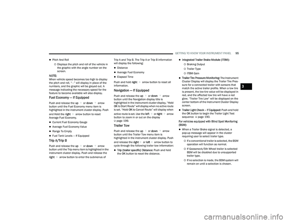
Pitch And Roll
Displays the pitch and roll of the vehicle in
the graphic with the angle number on the
screen.
NOTE:When vehicle speed becomes too high to display
the pitch and roll, “- -” will display in place of the
numbers, and the graphic will be greyed out. A
message indicating the necessary speed for the
feature to become available will also display.
Fuel Economy — If Equipped
Push and release the up or down arrow
button until the Fuel Economy menu item is
highlighted in the instrument cluster display. Push
and Hold the right arrow button to reset
Average Fuel Economy.
Current Fuel Economy Gauge
Average Fuel Economy Value
Range To Empty
Fuel Tank Levels — If Equipped
Trip A/Trip B
Push and release the up or down arrow
button until the Trip menu item is highlighted in the
instrument cluster display. Push and release the
right arrow button to enter the submenus of Trip A and Trip B. The Trip A or Trip B information
will display the following:
Distance
Average Fuel Economy
Elapsed Time
Push and hold right arrow button to reset all
information.
Navigation — If Equipped
Push and release the up or down arrow
button until the Navigation display title is
highlighted in the instrument cluster display, “Hold
OK to Start Route” will display when no active route
is set. “Hold OK to Cancel Route” will display when
active route is set. Use the left or right arrow
button to zoom in or out on the display
Ú page 199.
Trailer Tow
Push and release the up or down arrow
button until the Trailer Tow menu item is
highlighted in the instrument cluster display. Push
and release the right or left arrow button to
cycle through the following trailer tow information:
Trip (trailer specific) Distance: Push and hold
the OK button to reset the distance.
Integrated Trailer Brake Module (ITBM):
Braking Output
Trailer Type
ITBM Gain
Trailer Tire Pressure Monitoring: The Instrument
Cluster Display will display the Trailer Tire Pres -
sure for a connected trailer with sensors that
match the active trailer profile. When a low tire
is present, the low tire value will be displayed in
red, and the affected low tire will have a red
glow. “Trailer Tire Low“ will be displayed on the
center bottom of the Instrument Cluster Display
screen.
Trailer Light Check – If Equipped: Push and hold
the OK button to begin the Trailer Light Test
sequence Ú page 190.
For vehicles equipped with Blind Spot Monitoring
(BSM):
When a Trailer Brake signal is detected, a
pop-up message will appear in the cluster
requiring user to select trailer type.
If a conventional trailer is selected, the BSM
operation will function as normal.
If Gooseneck/5th Wheel trailer is selected
BSM will be disabled due to unsupported
trailer type.
If no selection is made, the BSM system will
remain on until a selection is chosen.
3
23_DPF_OM_EN_USC_t.book Page 95
Page 99 of 444
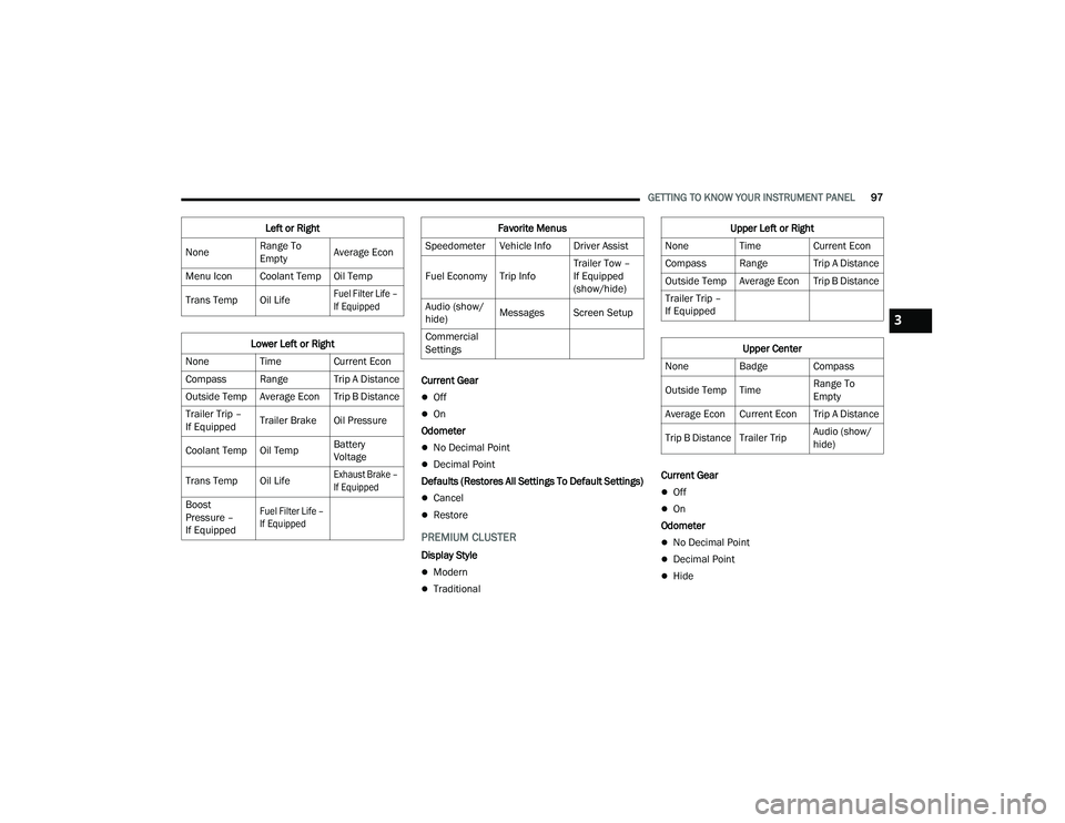
GETTING TO KNOW YOUR INSTRUMENT PANEL97
Current Gear
Off
On
Odometer
No Decimal Point
Decimal Point
Defaults (Restores All Settings To Default Settings)
Cancel
Restore
PREMIUM CLUSTER
Display Style
Modern
Traditional Current Gear
Off
On
Odometer
No Decimal Point
Decimal Point
Hide
Left or Right
None Range To
EmptyAverage Econ
Menu Icon Coolant Temp Oil Temp
Trans Temp Oil Life
Fuel Filter Life –
If Equipped
Lower Left or Right
None Time Current Econ
Compass Range Trip A Distance
Outside Temp Average Econ Trip B Distance
Trailer Trip –
If Equipped Trailer Brake Oil Pressure
Coolant Temp Oil Temp Battery
Voltage
Trans Temp Oil Life
Exhaust Brake –
If Equipped
Boost
Pressure –
If Equipped
Fuel Filter Life –
If Equipped
Favorite Menus
Speedometer Vehicle Info Driver Assist
Fuel Economy Trip Info Trailer Tow –
If Equipped
(show/hide)
Audio (show/
hide) Messages Screen Setup
Commercial
SettingsUpper Left or Right
None Time Current Econ
Compass Range Trip A Distance
Outside Temp Average Econ Trip B Distance
Trailer Trip –
If Equipped
Upper Center
None Badge Compass
Outside Temp Time Range To
Empty
Average Econ Current Econ Trip A Distance
Trip B Distance Trailer Trip Audio (show/
hide)
3
23_DPF_OM_EN_USC_t.book Page 97