heater RAM CHASSIS CAB 2023 Owners Manual
[x] Cancel search | Manufacturer: RAM, Model Year: 2023, Model line: CHASSIS CAB, Model: RAM CHASSIS CAB 2023Pages: 444, PDF Size: 20.51 MB
Page 6 of 444
4
GETTING TO KNOW YOUR
INSTRUMENT PANEL
MIDLINE INSTRUMENT CLUSTER — GASOLINE.....78
Midline Instrument Cluster Descriptions ........79
HIGHLINE INSTRUMENT CLUSTER — GASOLINE...80
Highline Instrument Cluster Descriptions.......81
PREMIUM INSTRUMENT CLUSTER — GASOLINE ..82
Premium Instrument Cluster Descriptions —
Gasoline ............................................................83
BASE INSTRUMENT CLUSTER — DIESEL ........... 84
Diesel Instrument Cluster ...............................85
MIDLINE INSTRUMENT CLUSTER — DIESEL ...... 86
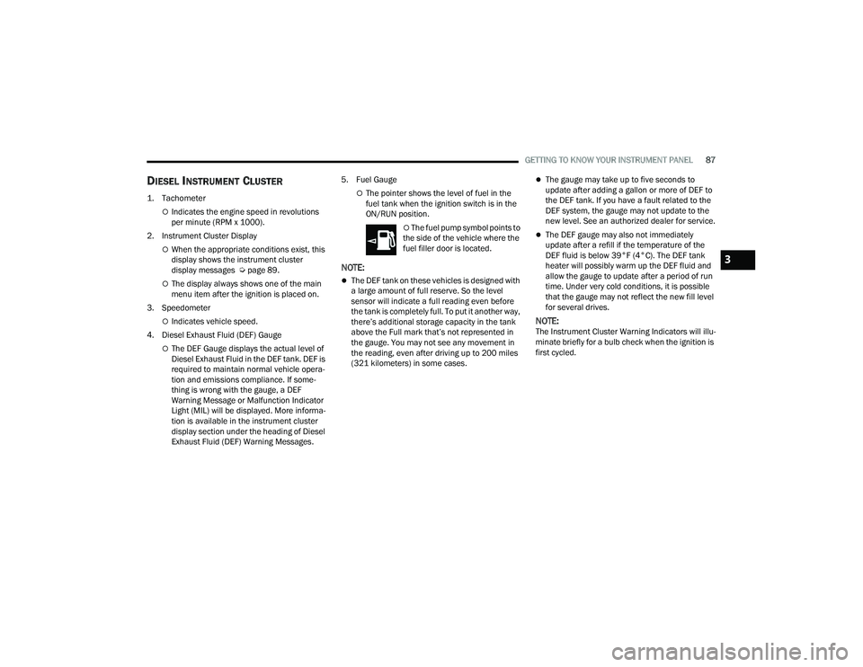
Diesel Instrument Cluster ...............................87
PREMIUM INSTRUMENT CLUSTER — DIESEL .... 88
Premium Instrument Cluster Descriptions —
Diesel ................................................................89
INSTRUMENT CLUSTER DISPLAY ........................ 89
Instrument Cluster Display Location and
Controls .............................................................90
Oil Life Reset ....................................................92
Display Menu Items .........................................93
Diesel Messages And Warnings ......................98
Battery Saver On/Battery Saver Mode
Message — Electrical Load Reduction
Actions — If Equipped ................................... 101 WARNING LIGHTS AND MESSAGES ................. 102
Red Warning Lights ....................................... 103
Yellow Warning Lights ................................... 105Yellow Indicator Lights .................................. 108
Green Indicator Lights .................................. 109
White Indicator Lights ................................... 110Blue Indicator Lights ..................................... 111
ONBOARD DIAGNOSTIC SYSTEM — OBD II ..... 111
Onboard Diagnostic System
(OBD II) Cybersecurity ................................... 111
EMISSIONS INSPECTION AND MAINTENANCE
PROGRAMS.......................................................... 112
STARTING AND OPERATING
STARTING THE ENGINE— GASOLINE ENGINE.. 113
Automatic Transmission ............................... 113
AutoPark — Rotary Shifter and 8-Speed
Transmission Only ......................................... 113
Tip Start Feature .......................................... 115
Keyless Enter ‘n Go™ — Ignition................... 115Normal Starting Using ENGINE START/STOP
Button ........................................................... 115
Cold Weather Operation
(Below –22°F Or −30°C) ............................ 117
After Starting ................................................. 117 STARTING THE ENGINE — DIESEL ENGINE....... 117
Automatic Transmission ............................... 117
Keyless Enter ‘n Go™ — Ignition .................. 117
Extreme Cold Weather .................................. 119Normal Starting Procedure — Engine Manifold
Air Temperature Above 66°F (19°C) .......... 119
Starting Procedure — Engine Manifold
Air Temperature 0°F To 66°F
(–18°C to 19°C) ........................................... 120
Starting Procedure — Engine Manifold Air
Temperature Below 0°F (-18°C) ................. 121
Starting Fluids ............................................... 121
NORMAL OPERATION — DIESEL ENGINE ......... 122
Cold Weather Precautions ............................ 122
Engine Idling ................................................. 124
Noise .............................................................. 124
Stopping The Engine ..................................... 125Idle Shutdown ............................................... 125Programmable Maximum Vehicle Speed .... 126
Operating Precautions .................................. 126Cooling System Tips ...................................... 126
Diesel Particulate Filter (DPF) Manual
Regeneration — If Equipped ......................... 127
ENGINE BLOCK HEATER — IF EQUIPPED .......... 127
ENGINE BREAK-IN RECOMMENDATIONS—
GASOLINE ENGINE .............................................. 127
23_DPF_OM_EN_USC_t.book Page 4
Page 12 of 444

10
SYMBOLS KEY
If you do not read the entire Owner’s Manual, you may miss important
information. Observe all Cautions and Warnings.
VAN CONVERSIONS/CAMPERS
The New Vehicle Limited Warranty does not apply to body modifications or
special equipment installed by van conversion/camper manufacturers/body
builders. US residents refer to the Warranty Information, Section 2.1.C.
Canadian residents refer to the “What Is Not Covered” section of the Warranty
Information. Such equipment includes video monitors, DVD/Blu-Ray™,
heaters, stoves, refrigerators, etc. For warranty coverage and service on these
items, contact the applicable manufacturer.
Operating instructions for the special equipment installed by the conversion/
camper manufacturer should also be supplied with your vehicle. For any
additional instructions, please contact your conversion/camper manufacturer.
To obtain dimensional and technical specifications for your vehicle, refer to the
Body Builder’s Guide at
https://www.ramtrucks.com/ram-commercial/
body-builders-guide.html.
VEHICLE MODIFICATIONS/ALTERATIONS
SYMBOL GLOSSARY
Some car components have colored labels with symbols indicating
precautions to be observed when using this component. It is important to
follow all warnings when operating your vehicle. See below for the definition of
each symbol Ú page 102.
WARNING!
These statements apply to operating procedures
that could result in a collision, bodily injury and/or
death.
CAUTION! These statements apply to procedures that could
result in damage to your vehicle.
NOTE: A suggestion which will improve installation,
operation, and reliability. If not followed, may result
in damage.
TIP: General ideas/solutions/suggestions on easier
use of the product or functionality.
PAGE REFERENCE
ARROW
Follow this reference for additional information on
a particular feature.
FOOTNOTE Supplementary and relevant information
pertaining to the topic.
WARNING!
Any modifications or alterations to this vehicle could seriously affect its
roadworthiness and safety and may lead to a collision resulting in serious
injury or death.
23_DPF_OM_EN_USC_t.book Page 10
Page 24 of 444

22GETTING TO KNOW YOUR VEHICLE
(Continued)
REMOTE START WINDSHIELD WIPER
D
E-ICER ACTIVATION — IF EQUIPPED
When Remote Start is active and the outside
ambient temperature is less than 33°F (0.6°C),
the Windshield Wiper De-Icer will activate. Exiting
Remote Start will resume its previous operation. If
the Windshield Wiper De-Icer was active, the timer
and operation will continue.
REMOTE START ABORT MESSAGE
One of the following messages will display in the
instrument cluster display if the vehicle fails to
remote start or exits Remote Start prematurely:
Remote Start Canceled — Door Open
Remote Start Canceled — Hood Open
Remote Start Canceled — Fuel Low
Remote Start Canceled — System Fault
Remote Start Disabled — Start Vehicle to Reset
The instrument cluster display message stays
active until the ignition is placed in the ON/RUN
position.
REMOTE START — IF EQUIPPED (DIESEL)
This system uses the key fob to start the
engine conveniently from outside the
vehicle while still maintaining security. The system has a range of approximately 300 ft
(91 m).
Remote Start is used to defrost windows in cold
weather, and to reach a comfortable climate in all
ambient conditions before the driver enters the
vehicle.
NOTE:
Obstructions between the vehicle and the key
fob may reduce this range.
The Remote Start system will wait for the Wait
To Start Light
Úpage 109 to extinguish before
cranking the engine. This allows time for the
intake heater to preheat the incoming air, and is
normal operation in cold weather Ú page 427.
HOW TO USE REMOTE START
Push and release the Remote Start button on the
key fob twice within five seconds. The vehicle
doors will lock, the parking lights will flash, and the
horn will chirp twice (if programmed). Then, the
engine will start, and the vehicle will remain in the
Remote Start mode for a 15 minute cycle.
Pushing the Remote Start button a third time shuts
the engine off.
To drive the vehicle, push the unlock button, and
place the ignition in the ON/RUN position. All of the following conditions must be met before
the engine will remote start:
Gear selector in PARK
Doors closed
Hood closed
Hazard switch off
Brake switch inactive (brake pedal not pressed)
Battery at an acceptable charge level
Panic button not pushed
Fuel meets minimum requirement
Water In Fuel Indicator Light is not illuminated
Wait To Start Light is not illuminated
Malfunction Indicator Light (MIL) is not illumi
-
nated
For additional functions of the Remote Start
system, see Ú page 21.
WARNING!
Do not start or run an engine in a closed
garage or confined area. Exhaust gas contains
carbon monoxide (CO) which is odorless and
colorless. Carbon monoxide is poisonous and
can cause serious injury or death when
inhaled.
23_DPF_OM_EN_USC_t.book Page 22
Page 30 of 444
28GETTING TO KNOW YOUR VEHICLE
HEATED STEERING WHEEL —
I
F EQUIPPED
The steering wheel contains a heating
element that helps warm your hands in
cold weather. The heated steering wheel
has only one temperature setting. Once
the heated steering wheel has been turned on, it
will stay on until the operator turns it off. The
heated steering wheel may not turn on when it is
already warm.
The heated steering wheel button is located on the
center of the instrument panel below the radio
screen, or within the climate or comfort screen of
the touchscreen.
NOTE:If the vehicle is equipped with a 12-inch radio,
there will only be control buttons through the
touchscreen.
Press the heated steering wheel button once to
turn the heating element on.
Press the heated steering wheel button a
second time to turn the heating element off.
NOTE:The engine must be running for the heated
steering wheel to operate.
For information on use with the Remote Start
system, see Ú page 21.
UCONNECT VOICE RECOGNITION —
IF EQUIPPED
INTRODUCING VOICE RECOGNITION
Start using Uconnect Voice Recognition with these
helpful quick tips. It provides the key Voice
Commands and tips you need to know to control
your vehicle’s Voice Recognition (VR) system.
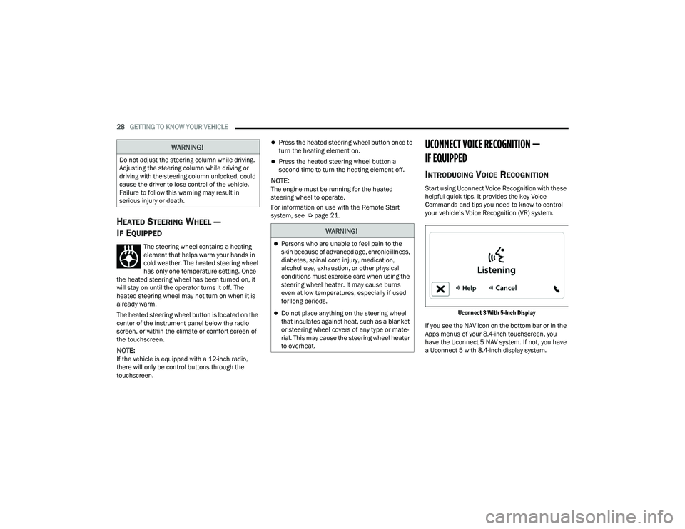
Uconnect 3 With 5-inch Display
If you see the NAV icon on the bottom bar or in the
Apps menus of your 8.4-inch touchscreen, you
have the Uconnect 5 NAV system. If not, you have
a Uconnect 5 with 8.4-inch display system.
WARNING!
Do not adjust the steering column while driving.
Adjusting the steering column while driving or
driving with the steering column unlocked, could
cause the driver to lose control of the vehicle.
Failure to follow this warning may result in
serious injury or death.
WARNING!
Persons who are unable to feel pain to the
skin because of advanced age, chronic illness,
diabetes, spinal cord injury, medication,
alcohol use, exhaustion, or other physical
conditions must exercise care when using the
steering wheel heater. It may cause burns
even at low temperatures, especially if used
for long periods.
Do not place anything on the steering wheel
that insulates against heat, such as a blanket
or steering wheel covers of any type or mate -
rial. This may cause the steering wheel heater
to overheat.
23_DPF_OM_EN_USC_t.book Page 28
Page 36 of 444

34GETTING TO KNOW YOUR VEHICLE
Power Lumbar — If Equipped
Vehicles equipped with power driver or passenger
seats may also be equipped with power lumbar.
The power lumbar switch is located on the
outboard side of the power seat. Push the switch
forward to increase the lumbar support. Push the
switch rearward to decrease the lumbar support.
Lumbar Control Switch
Easy Entry/Exit Seat — If Equipped
This feature provides automatic driver’s seat
positioning to enhance driver mobility when
entering and exiting the vehicle.
The distance the driver’s seat moves depends on
where you have the driver’s seat positioned when
you place the vehicle’s ignition in the OFF position.
When you place the vehicle’s ignition in the OFF
position, the driver’s seat will move about
2.4 inches (6 cm) rearward if the driver’s seat position is greater than or equal to 2.7 inches
(6.77 cm) forward of the rear stop. The seat will
return to its previously set position when you
place the ignition into the ACC or ON/RUN posi
-
tion.
When you remove the key fob from the ignition,
the driver’s seat will move to a position
0.3 inches (0.77 cm) forward of the rear stop if
the driver’s seat position is between 0.9 inches
and 2.7 inches (2.27 cm and 6.77 cm) forward
of the rear stop. The seat will return to its previ -
ously set position when you place the ignition to
the ACC or ON/RUN position.
The Easy Entry/Easy Exit feature is disabled
when the driver’s seat position is less than
0.9 inches (2.27 cm) forward of the rear stop. At
this position, there is no benefit to the driver by
moving the seat for Easy Exit or Easy Entry.
When enabled in Uconnect Settings, Easy Entry
and Easy Exit positions are stored in each memory
setting profile Ú page 30.
NOTE:The Easy Entry/Exit feature is enabled or disabled
through the programmable features in the
Uconnect system Ú page 199.
HEATED SEATS — IF EQUIPPED
On some models, the front and rear seats may be
equipped with heaters located in the seat cushions
and seatbacks.
WARNING!
Persons who are unable to feel pain to the
skin because of advanced age, chronic illness,
diabetes, spinal cord injury, medication,
alcohol use, exhaustion or other physical
condition must exercise care when using the
seat heater. It may cause burns even at low
temperatures, especially if used for long
periods of time.
Do not place anything on the seat or seatback
that insulates against heat, such as a blanket
or cushion. This may cause the seat heater to
overheat. Sitting in a seat that has been over -
heated could cause serious burns due to the
increased surface temperature of the seat.
23_DPF_OM_EN_USC_t.book Page 34
Page 66 of 444
64GETTING TO KNOW YOUR VEHICLE
Mix Mode
Air is directed through the floor, defrost,
and side window demister outlets. This
setting works best in cold or snowy
conditions that require extra heat to the
windshield. This setting is good for maintaining
comfort while reducing moisture on the
windshield.
AUTOMATIC TEMPERATURE CONTROL
(ATC)
Automatic Operation
1. Push the AUTO button on the faceplate, or the
AUTO button on the touchscreen on the
Automatic Temperature Control (ATC) Panel.
2. Next, adjust the temperature you would like the system to maintain by adjusting the driver
and passenger temperature control buttons.
Once the desired temperature is displayed, the
system will achieve and automatically
maintain that comfort level.
3. When the system is set up for your comfort level, it is not necessary to change the
settings. You will experience the greatest
efficiency by simply allowing the system to
function automatically.
NOTE:
It is not necessary to move the temperature
settings for cold or hot vehicles. The system
automatically adjusts the temperature, mode,
and blower speed to provide comfort as quickly
as possible.
The temperature can be displayed in U.S. or
Metric units by selecting the U.S./Metric within
Uconnect Settings Ú page 199.
To provide you with maximum comfort in the
Automatic mode during cold start-ups, the blower
fan will remain on low until the engine warms up.
The blower will increase in speed and transition
into Auto mode.
Manual Operation Override
This system offers a full complement of manual
override features. The AUTO symbol in the front
ATC display will be turned off when the system is
being used in the manual mode.
CLIMATE VOICE RECOGNITION —
I
F EQUIPPED
Adjust vehicle temperatures hands-free and keep
everyone comfortable while you keep moving
ahead. Push the VR button on the steering wheel. After the
beep, say one of the following commands:
“
Set driver temperature to 70 degrees ”
“Set passenger temperature to 70 degrees ”
Did you know: Voice Command for Climate may
only be used to adjust the interior temperature of
your vehicle. Voice Command will not work to
adjust the heated seats or steering wheel if
equipped.
OPERATING TIPS
Refer to the chart at the end of this section for
suggested control settings for various weather
conditions.
Summer Operation
The engine cooling system must be protected with
a high-quality antifreeze coolant to provide proper
corrosion protection and to protect against engine
overheating. OAT coolant (conforming to
MS.90032) is recommended.
Winter Operation
To ensure the best possible heater and defroster
performance, make sure the engine cooling
system is functioning properly and the proper
amount, type, and concentration of coolant is
used. Use of the Air Recirculation mode during
Winter months is not recommended, because it
may cause window fogging.
23_DPF_OM_EN_USC_t.book Page 64
Page 87 of 444
GETTING TO KNOW YOUR INSTRUMENT PANEL85
DIESEL INSTRUMENT CLUSTER
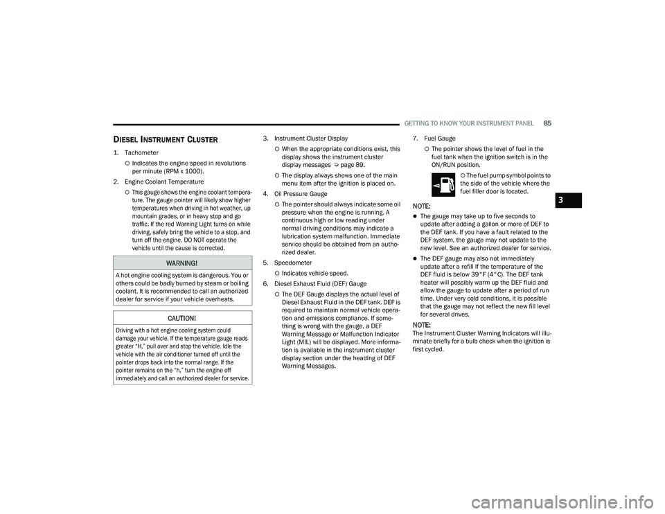
1. Tachometer
Indicates the engine speed in revolutions
per minute (RPM x 1000).
2. Engine Coolant Temperature
This gauge shows the engine coolant tempera -
ture. The gauge pointer will likely show higher
temperatures when driving in hot weather, up
mountain grades, or in heavy stop and go
traffic. If the red Warning Light turns on while
driving, safely bring the vehicle to a stop, and
turn off the engine. DO NOT operate the
vehicle until the cause is corrected.
3. Instrument Cluster Display
When the appropriate conditions exist, this
display shows the instrument cluster
display messages Ú
page 89.
The display always shows one of the main
menu item after the ignition is placed on.
4. Oil Pressure Gauge
The pointer should always indicate some oil
pressure when the engine is running. A
continuous high or low reading under
normal driving conditions may indicate a
lubrication system malfunction. Immediate
service should be obtained from an autho -
rized dealer.
5. Speedometer
Indicates vehicle speed.
6. Diesel Exhaust Fluid (DEF) Gauge
The DEF Gauge displays the actual level of
Diesel Exhaust Fluid in the DEF tank. DEF is
required to maintain normal vehicle opera -
tion and emissions compliance. If some -
thing is wrong with the gauge, a DEF
Warning Message or Malfunction Indicator
Light (MIL) will be displayed. More informa -
tion is available in the instrument cluster
display section under the heading of DEF
Warning Messages. 7. Fuel Gauge
The pointer shows the level of fuel in the
fuel tank when the ignition switch is in the
ON/RUN position.
The fuel pump symbol points to
the side of the vehicle where the
fuel filler door is located.
NOTE:
The gauge may take up to five seconds to
update after adding a gallon or more of DEF to
the DEF tank. If you have a fault related to the
DEF system, the gauge may not update to the
new level. See an authorized dealer for service.
The DEF gauge may also not immediately
update after a refill if the temperature of the
DEF fluid is below 39°F (4°C). The DEF tank
heater will possibly warm up the DEF fluid and
allow the gauge to update after a period of run
time. Under very cold conditions, it is possible
that the gauge may not reflect the new fill level
for several drives.
NOTE:The Instrument Cluster Warning Indicators will illu -
minate briefly for a bulb check when the ignition is
first cycled.
WARNING!
A hot engine cooling system is dangerous. You or
others could be badly burned by steam or boiling
coolant. It is recommended to call an authorized
dealer for service if your vehicle overheats.
CAUTION!
Driving with a hot engine cooling system could
damage your vehicle. If the temperature gauge reads
greater “H,” pull over and stop the vehicle. Idle the
vehicle with the air conditioner turned off until the
pointer drops back into the normal range. If the
pointer remains on the “h,” turn the engine off
immediately and call an authorized dealer for service.
3
23_DPF_OM_EN_USC_t.book Page 85
Page 89 of 444
GETTING TO KNOW YOUR INSTRUMENT PANEL87
DIESEL INSTRUMENT CLUSTER
1. Tachometer
Indicates the engine speed in revolutions
per minute (RPM x 1000).
2. Instrument Cluster Display
When the appropriate conditions exist, this
display shows the instrument cluster
display messages Ú page 89.
The display always shows one of the main
menu item after the ignition is placed on.
3. Speedometer
Indicates vehicle speed.
4. Diesel Exhaust Fluid (DEF) Gauge
The DEF Gauge displays the actual level of
Diesel Exhaust Fluid in the DEF tank. DEF is
required to maintain normal vehicle opera -
tion and emissions compliance. If some -
thing is wrong with the gauge, a DEF
Warning Message or Malfunction Indicator
Light (MIL) will be displayed. More informa -
tion is available in the instrument cluster
display section under the heading of Diesel
Exhaust Fluid (DEF) Warning Messages. 5. Fuel Gauge
The pointer shows the level of fuel in the
fuel tank when the ignition switch is in the
ON/RUN position.
The fuel pump symbol points to
the side of the vehicle where the
fuel filler door is located.
NOTE:
The DEF tank on these vehicles is designed with
a large amount of full reserve. So the level
sensor will indicate a full reading even before
the tank is completely full. To put it another way,
there’s additional storage capacity in the tank
above the Full mark that’s not represented in
the gauge. You may not see any movement in
the reading, even after driving up to 200 miles
(321 kilometers) in some cases.
The gauge may take up to five seconds to
update after adding a gallon or more of DEF to
the DEF tank. If you have a fault related to the
DEF system, the gauge may not update to the
new level. See an authorized dealer for service.
The DEF gauge may also not immediately
update after a refill if the temperature of the
DEF fluid is below 39°F (4°C). The DEF tank
heater will possibly warm up the DEF fluid and
allow the gauge to update after a period of run
time. Under very cold conditions, it is possible
that the gauge may not reflect the new fill level
for several drives.
NOTE:The Instrument Cluster Warning Indicators will illu -
minate briefly for a bulb check when the ignition is
first cycled.
3
23_DPF_OM_EN_USC_t.book Page 87
Page 119 of 444

STARTING AND OPERATING117
(Continued)
COLD WEATHER OPERATION
(B
ELOW –22°F OR −30°C)
To ensure reliable starting at these temperatures,
use of an externally powered electric engine block
heater (available from an authorized dealer) is
recommended.
AFTER STARTING
The idle speed is controlled automatically, and it
will decrease as the engine warms up.
STARTING THE ENGINE — DIESEL ENGINE
Before starting your vehicle, adjust your seat,
adjust both inside and outside mirrors, and fasten
your seat belts.
The starter should not be operated for more than
25-second intervals. Waiting two minutes between
such intervals will protect the starter from
overheating.
AUTOMATIC TRANSMISSION
Start the engine with the transmission in the
NEUTRAL or PARK position. Apply the brake before
shifting to any driving range.
Tip Start Feature
Do not press the accelerator. Place the ignition
switch briefly to the START position and release it.
The starter motor will continue to run and will
automatically disengage when the engine is
running.
KEYLESS ENTER ‘N GO™ — IGNITION
This feature allows the driver to operate the
ignition switch with the push of a button, as long as
the Remote Start/Keyless Enter ‘n Go™ key fob is
in the passenger compartment.
Normal Starting
USING THE ENGINE START/STOP BUTTON
1. The transmission must be in PARK or NEUTRAL.
2. Press and hold the brake pedal while pushing the ENGINE START/STOP button once.
3. The system takes over and attempts to start the vehicle. If the vehicle fails to start, the
starter will disengage automatically after 25
seconds.
4. If you wish to stop the cranking of the engine prior to the engine starting, remove your foot
from the brake pedal and push the ENGINE
START/STOP button again.
WARNING!
Do not leave children or animals inside parked
vehicles in hot weather. Interior heat build-up
may cause serious injury or death.
When leaving the vehicle, always remove the
key fob and lock your vehicle.
Never leave children alone in a vehicle, or with
access to an unlocked vehicle. Allowing chil -
dren to be in a vehicle unattended is
dangerous for a number of reasons. A child or
others could be seriously or fatally injured.
Children should be warned not to touch the
parking brake, brake pedal or the gear
selector. Do not leave the key fob in or near
the vehicle (or in a location accessible to chil -
dren), and do not leave the ignition of a
vehicle equipped with Keyless Enter ‘n Go™ in
the ACC or ON/RUN position. A child could
operate power windows, other controls, or
move the vehicle.
WARNING!
4
23_DPF_OM_EN_USC_t.book Page 117
Page 120 of 444

118STARTING AND OPERATING
NOTE:
Normal starting of either a cold or a warm
engine is obtained without pumping or pressing
the accelerator pedal.
Under cold weather conditions, the engine may
not immediately crank if the Wait to Start Indi -
cator Light is illuminated. This is normal opera -
tion. For vehicles equipped with Keyless
Enter ‘n Go™, the vehicle will automatically
crank when the “Wait to Start” time has elapsed
Ú page 120.
TO TURN OFF THE ENGINE USING ENGINE
START/STOP BUTTON
1. Place the gear selector in PARK, then push
and release the ENGINE START/STOP button.
2. The ignition will return to the OFF position.
3. If the gear selector is not in PARK and the ENGINE START/STOP button is pushed once,
the instrument cluster will display a “Vehicle
Not In Park” message and the engine will
remain running. Never leave a vehicle out of
the PARK position, or it could roll.
4. If the gear selector is in NEUTRAL, and the vehicle speed below 5 mph (8 km/h), pushing
the ENGINE START/STOP button once will turn
the engine off. The ignition will remain in the
ACC position. 5. If the vehicle speed is above 5 mph (8 km/h),
the ENGINE START/STOP button must be held
for two seconds (or three short pushes in a
row) to turn the engine off. The ignition will
remain in the ACC position (NOT the OFF
position) if the engine is turned off when the
transmission is not in PARK.
NOTE:If the ignition is left in the ACC or ON/RUN (engine
not running) position and the transmission is in
PARK, the system will automatically time out after
30 minutes of inactivity and the ignition return to
the OFF position.
ENGINE START/STOP BUTTON FUNCTIONS —
WITH DRIVER’S FOOT OFF THE BRAKE PEDAL
(IN PARK OR NEUTRAL POSITION)
The ENGINE START/STOP button operates similar
to an ignition switch. It has three positions: OFF,
ACC, and RUN. To change the ignition switch
positions without starting the vehicle and use the
accessories follow these steps:
1. Start with the ignition in the OFF position.
2. Push the ENGINE START/STOP button once to change the ignition to the ACC position. 3. Push the ENGINE START/STOP button a
second time to change the ignition to the RUN
position.
4. Push the ENGINE START/STOP button a third time to return the ignition to the OFF position.
Keyless Enter ‘n Go™ Starting Procedure —
Engine Manifold Air Temperature 0°F To
66°F (–18°C to 19°C)
NOTE:The temperature displayed in the instrument
cluster does not necessarily reflect the engine
manifold air temperature Ú page 89. When
engine temperatures fall below 66°F (19°C) the
Wait To Start Indicator Light will remain on indi -
cating the intake air heater system is active.
Follow the steps in the “Normal Starting”
procedure except:
1. Pushing the engine start button with the driver’s foot on the brake will move the
ignition from OFF or ACC to RUN, and will
illuminate the Wait To Start Indicator Light.
The engine will not immediately crank, this is
normal operation.
2. The Wait To Start Indicator Light will remain on for a period of time that varies depending on
the engine temperature.
23_DPF_OM_EN_USC_t.book Page 118