rear view mirror RAM CHASSIS CAB 2023 Owners Manual
[x] Cancel search | Manufacturer: RAM, Model Year: 2023, Model line: CHASSIS CAB, Model: RAM CHASSIS CAB 2023Pages: 444, PDF Size: 20.51 MB
Page 4 of 444
2
INTRODUCTION
SYMBOLS KEY ........................................................ 10
VAN CONVERSIONS/CAMPERS ........................... 10
VEHICLE MODIFICATIONS/ALTERATIONS .......... 10
SYMBOL GLOSSARY.............................................. 10
GETTING TO KNOW YOUR VEHICLE
KEYS ....................................................................... 15
Key Fob .............................................................15
SENTRY KEY ........................................................... 18
IGNITION SWITCH .................................................. 18
Keyless Enter ‘n Go™ Ignition .........................18
REMOTE START — IF EQUIPPED (GASOLINE) ... 20
How To Use Remote Start ................................20
To Exit Remote Start Mode ..............................21
Remote Start Front Defrost Activation —
If Equipped........................................................21
Remote Start Comfort Systems —
If Equipped........................................................21
Remote Start Windshield Wiper De-Icer
Activation — If Equipped ..................................22
Remote Start Abort Message ..........................22
REMOTE START — IF EQUIPPED (DIESEL) .......... 22
How To Use Remote Start ................................22
VEHICLE SECURITY SYSTEM — IF EQUIPPED ..... 23
To Arm The System ..........................................23
To Disarm The System .....................................23
Rearming Of The System .................................23
Security System Manual Override ...................23 DOORS ....................................................................24
Manual Door Locks ..........................................24
Power Door Locks — If Equipped ....................24
Keyless Enter ‘n Go™ — Passive Entry
(If Equipped) .....................................................25
Automatic Unlock Doors On Exit —
If Equipped........................................................26
Automatic Door Locks —If Equipped ...............27
Child-Protection Door Lock —If Equipped .......27
STEERING WHEEL .................................................27
Tilt Steering Column .........................................27
Heated Steering Wheel — If Equipped ............28
UCONNECT VOICE RECOGNITION —
IF EQUIPPED .......................................................... 28
Introducing Voice Recognition.........................28
Basic Voice Commands ...................................29
Get Started .......................................................29
Additional Information .....................................30
DRIVER MEMORY SETTINGS — IF EQUIPPED .....30
Programming The Memory Feature ................30
Linking And Unlinking The Remote Keyless
Entry Key Fob To Memory ................................31
Memory Position Recall ...................................31 SEATS ...................................................................... 31
Manual Front Seat Adjustment —
If Equipped .......................................................32
Power Adjustment (Front Seats) —
If Equipped .......................................................33
Heated Seats — If Equipped ............................ 34
Ventilated Seats — If Equipped .......................35
Head Restraints ............................................... 36
DRIVER ADJUSTABLE PEDALS —
IF EQUIPPED .......................................................... 38
MIRRORS ............................................................... 39
Inside Rearview Mirror..................................... 39
Illuminated Vanity Mirror — If Equipped ......... 41
Outside Mirrors ................................................ 42
Outside Automatic Dimming Mirror —
If Equipped .......................................................43
Power Mirrors — If Equipped .......................... 43
Power Folding Outside Mirrors For Standard
And Trailer Tow — If Equipped ......................... 44
Automatic Power Folding Mirrors —
If Equipped .......................................................44
Power Convex Mirror Switch —
If Equipped .......................................................45
23_DPF_OM_EN_USC_t.book Page 2
Page 41 of 444
GETTING TO KNOW YOUR VEHICLE39
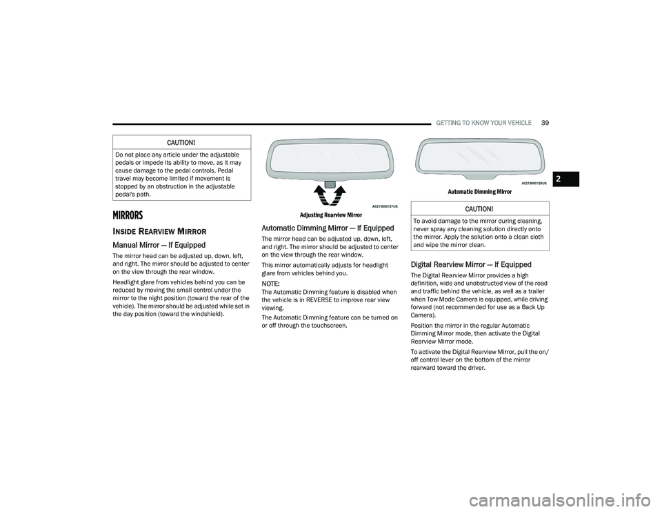
MIRRORS
INSIDE REARVIEW MIRROR
Manual Mirror — If Equipped
The mirror head can be adjusted up, down, left,
and right. The mirror should be adjusted to center
on the view through the rear window.
Headlight glare from vehicles behind you can be
reduced by moving the small control under the
mirror to the night position (toward the rear of the
vehicle). The mirror should be adjusted while set in
the day position (toward the windshield).
Adjusting Rearview Mirror
Automatic Dimming Mirror — If Equipped
The mirror head can be adjusted up, down, left,
and right. The mirror should be adjusted to center
on the view through the rear window.
This mirror automatically adjusts for headlight
glare from vehicles behind you.
NOTE:The Automatic Dimming feature is disabled when
the vehicle is in REVERSE to improve rear view
viewing.
The Automatic Dimming feature can be turned on
or off through the touchscreen.
Automatic Dimming Mirror
Digital Rearview Mirror — If Equipped
The Digital Rearview Mirror provides a high
definition, wide and unobstructed view of the road
and traffic behind the vehicle, as well as a trailer
when Tow Mode Camera is equipped, while driving
forward (not recommended for use as a Back Up
Camera).
Position the mirror in the regular Automatic
Dimming Mirror mode, then activate the Digital
Rearview Mirror mode.
To activate the Digital Rearview Mirror, pull the on/
off control lever on the bottom of the mirror
rearward toward the driver.
CAUTION!
Do not place any article under the adjustable
pedals or impede its ability to move, as it may
cause damage to the pedal controls. Pedal
travel may become limited if movement is
stopped by an obstruction in the adjustable
pedal's path.
CAUTION!
To avoid damage to the mirror during cleaning,
never spray any cleaning solution directly onto
the mirror. Apply the solution onto a clean cloth
and wipe the mirror clean.
2
23_DPF_OM_EN_USC_t.book Page 39
Page 42 of 444
40GETTING TO KNOW YOUR VEHICLE
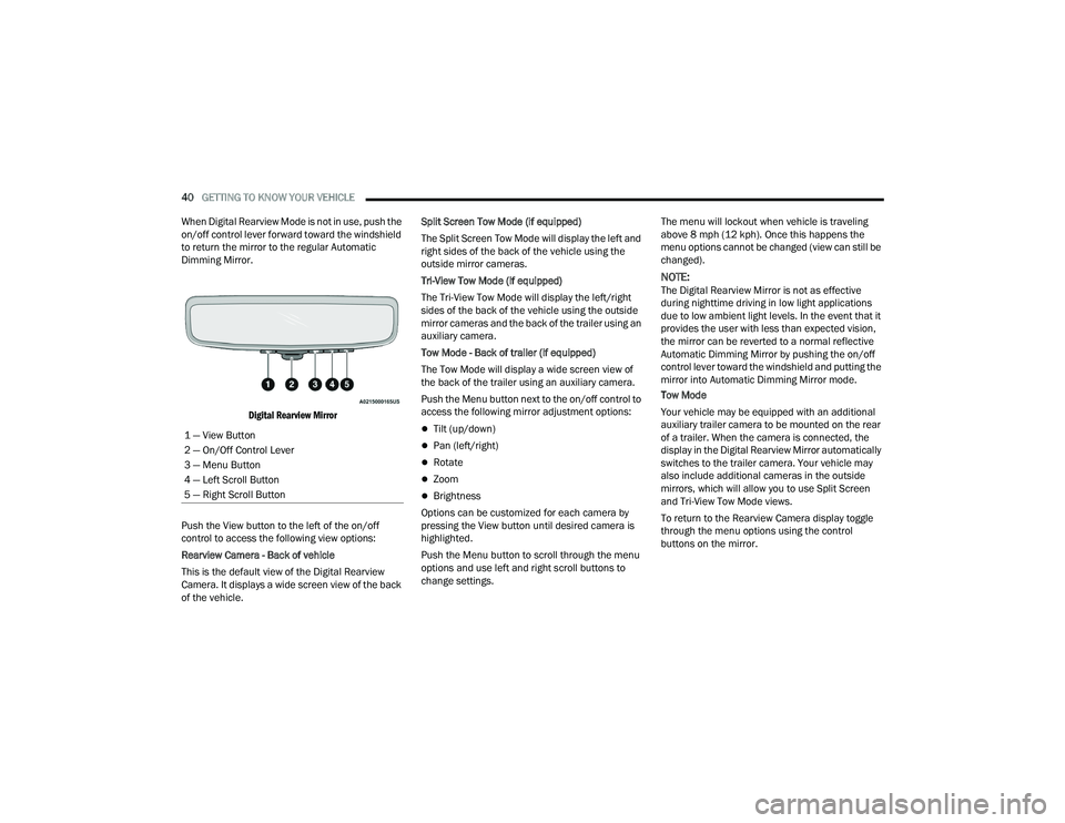
When Digital Rearview Mode is not in use, push the
on/off control lever forward toward the windshield
to return the mirror to the regular Automatic
Dimming Mirror.
Digital Rearview Mirror
Push the View button to the left of the on/off
control to access the following view options:
Rearview Camera - Back of vehicle
This is the default view of the Digital Rearview
Camera. It displays a wide screen view of the back
of the vehicle. Split Screen Tow Mode (if equipped)
The Split Screen Tow Mode will display the left and
right sides of the back of the vehicle using the
outside mirror cameras.
Tri-View Tow Mode (if equipped)
The Tri-View Tow Mode will display the left/right
sides of the back of the vehicle using the outside
mirror cameras and the back of the trailer using an
auxiliary camera.
Tow Mode - Back of trailer (if equipped)
The Tow Mode will display a wide screen view of
the back of the trailer using an auxiliary camera.
Push the Menu button next to the on/off control to
access the following mirror adjustment options:
Tilt (up/down)
Pan (left/right)
Rotate
Zoom
Brightness
Options can be customized for each camera by
pressing the View button until desired camera is
highlighted.
Push the Menu button to scroll through the menu
options and use left and right scroll buttons to
change settings. The menu will lockout when vehicle is traveling
above 8 mph (12 kph). Once this happens the
menu options cannot be changed (view can still be
changed).
NOTE:The Digital Rearview Mirror is not as effective
during nighttime driving in low light applications
due to low ambient light levels. In the event that it
provides the user with less than expected vision,
the mirror can be reverted to a normal reflective
Automatic Dimming Mirror by pushing the on/off
control lever toward the windshield and putting the
mirror into Automatic Dimming Mirror mode.
Tow Mode
Your vehicle may be equipped with an additional
auxiliary trailer camera to be mounted on the rear
of a trailer. When the camera is connected, the
display in the Digital Rearview Mirror automatically
switches to the trailer camera. Your vehicle may
also include additional cameras in the outside
mirrors, which will allow you to use Split Screen
and Tri-View Tow Mode views.
To return to the Rearview Camera display toggle
through the menu options using the control
buttons on the mirror.
1 — View Button
2 — On/Off Control Lever
3 — Menu Button
4 — Left Scroll Button
5 — Right Scroll Button
23_DPF_OM_EN_USC_t.book Page 40
Page 43 of 444
GETTING TO KNOW YOUR VEHICLE41
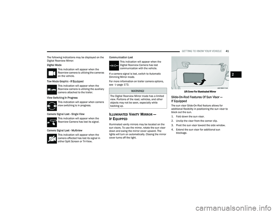
The following indications may be displayed on the
Digital Rearview Mirror:
Digital Mode This indication will appear when the
Rearview camera is utilizing the cameras
on the vehicle.
Tow Mode Graphic - If Equipped This indication will appear when the
Rearview camera is utilizing the auxiliary
camera attached to the trailer.
View Switching In Progress This indication will appear when camera
view switching is in progress.
Camera Signal Lost - Single View This indication will appear when the
Rearview Camera has lost its signal.
Camera Signal Lost - Multiview This indication will appear when the
camera effected has lost its signal in
either Split Screen or Tri-View. Communication Lost
This indication will appear when the
Digital Rearview Camera has lost
communication with the vehicle.
If a camera signal is lost, switch to Automatic
Dimming Mirror mode.
For more information on trailer camera options,
see Ú page 173.
ILLUMINATED VANITY MIRROR —
I
F EQUIPPED
Illuminated vanity mirrors may be located on the
sun visors. To use the mirror, rotate the sun visor
down and swing the mirror cover upward. The
lights will turn on automatically. Closing the mirror
cover turns off the light.
Lift Cover For Illuminated Mirror
Slide-On-Rod Features Of Sun Visor —
If Equipped
The sun visor Slide-On-Rod feature allows for
additional flexibility in positioning the sun visor to
block out the sun.
1. Fold down the sun visor.
2. Unclip the visor from the corner clip.
3. Pivot the sun visor toward the side window.
4. Extend the sun visor for additional sun
blockage.
WARNING!
The Digital Rearview Mirror mode has a limited
view. Portions of the road, vehicles, and other
objects may not be seen, especially while
backing up.
2
23_DPF_OM_EN_USC_t.book Page 41
Page 54 of 444
52GETTING TO KNOW YOUR VEHICLE
DAYTIME RUNNING LIGHTS (DRLS)
The Daytime Running Lights (DRLs) come on
whenever the engine is running, and the low
beams are not on. The lights will remain on until
the ignition is placed in the OFF or ACC position, or
the parking brake is engaged.
NOTE:
For vehicles sold in Canada, the Daytime
Running Lights will automatically deactivate
when the front fog lights are turned on.
If allowed by law in the country in which the
vehicle was purchased, the Daytime Running
Lights can be turned on and off using the
Uconnect system Úpage 199.
On some vehicles, the Daytime Running Lights
may deactivate, or reduce intensity, on one side
of the vehicle (when a turn signal is activated on
that side), or on both sides of the vehicle (when
the hazard warning lights are activated).
HIGH/LOW BEAM SWITCH
Push the multifunction lever toward the instrument
panel to switch the headlights to high beam.
Pulling the multifunction lever back toward the
steering wheel will turn the low beams back on.
AUTOMATIC HIGH BEAM HEADLAMP
C
ONTROL — IF EQUIPPED
The Automatic High Beam Headlamp Control
system provides increased forward lighting at night
by automating high beam control through the use
of a camera mounted on the inside rearview mirror
or a windshield mounted camera. These cameras
detect vehicle specific light and automatically
switch from high beams to low beams until the
approaching vehicle is out of view.
NOTE:
The Automatic High Beam Headlamp Control
can be turned on or off by selecting “ON” under
“Auto Dim High Beams” within your Uconnect
Settings Ú page 199, as well as turning the
headlight switch to the AUTO position.
Broken, muddy, or obstructed headlights and
taillights of vehicles in the field of view will
cause headlights to remain on longer (closer to
the vehicle). Also, dirt, film, and other obstruc -
tions on the windshield or camera lens will
cause the system to function improperly.
If the windshield or Automatic High Beam Head -
lamp Control mirror is replaced, the mirror must
be re-aimed to ensure proper performance. See
a local authorized dealer.
To opt out of the Automatic High-Beam Sensi -
tivity Control (default) and enter Reduced
High-Beam Sensitivity Control (not recom -
mended), toggle the multifunction lever six full
on/off cycles within 10 seconds of ignition ON.
The system will return to the default setting
when the ignition is placed in the OFF position.
FLASH-TO-PASS
You can signal another vehicle with your headlights
by lightly pulling the multifunction lever toward you.
This will cause the high beam headlights to turn on,
and remain on, until the lever is released.
AUTOMATIC HEADLIGHTS — IF EQUIPPED
This system automatically turns your headlights on
or off based on ambient light levels. To turn the
system on, rotate the headlight switch to the AUTO
position.
When the system is on, the Headlight Delay feature
is also on. This means the headlights will stay on
for up to 90 seconds after you place the ignition
into the OFF position. To turn the automatic
headlights off, turn the headlight switch out of the
AUTO position.
NOTE:The engine must be running before the headlights
will come on in the Automatic mode.
23_DPF_OM_EN_USC_t.book Page 52
Page 104 of 444
102GETTING TO KNOW YOUR INSTRUMENT PANEL
NOTE:
The charging system is independent from load
reduction. The charging system performs a diag-
nostic on the charging system continuously.
If the Battery Charge Warning Light is on it may
indicate a problem with the charging system
Ú page 104.
The electrical loads that may be switched off
(if equipped), and vehicle functions which can be
affected by load reduction:
Heated Seats/Vented Seats/Heated Wheel
Rear Defroster And Heated Mirrors
HVAC System
115 Volt AC Power Inverter System
Audio and Telematics System
Loss of the battery charge may indicate one or
more of the following conditions:
The charging system cannot deliver enough
electrical power to the vehicle system because
the electrical loads are larger than the capability
of charging system. The charging system is still
functioning properly.
Turning on all possible vehicle electrical loads
(e.g. HVAC to max settings, exterior and interior
lights, overloaded power outlets +12 Volts, 115
Volt AC, USB ports) during certain driving condi -
tions (city driving, towing, frequent stopping).
Installing options like additional lights, upfitter
electrical accessories, audio systems, alarms
and similar devices.
Unusual driving cycles (short trips separated by
long parking periods).
The vehicle was parked for an extended period
of time (weeks, months).
The battery was recently replaced and was not
charged completely.
The battery was discharged by an electrical load
left on when the vehicle was parked.
The battery was used for an extended period
with the engine not running to supply radio,
lights, chargers, +12 Volt portable appliances
like vacuum cleaners, game consoles and
similar devices.
What to do when an electrical load reduction
action message is present (“Battery Saver On” or
“Battery Saver Mode”)
During a trip:
Reduce power to unnecessary loads if possible:
Turn off redundant lights (interior or exte -
rior).
Check what may be plugged in to power
outlets +12 Volts, 115 Volt AC, USB ports.
Check HVAC settings (blower, temperature).
Check the audio settings (volume). After a trip:
Check if any aftermarket equipment was
installed (additional lights, upfitter electrical
accessories, audio systems, alarms) and review
specifications if any (load and Ignition Off Draw
currents).
Evaluate the latest driving cycles (distance,
driving time and parking time).
The vehicle should have service performed if
the message is still present during consecutive
trips and the evaluation of the vehicle and
driving pattern did not help to identify the cause.
WARNING LIGHTS AND MESSAGES
The warning/indicator lights will illuminate in the
instrument panel together with a dedicated
message and/or acoustic signal when applicable.
These indications are indicative and precautionary
and as such must not be considered as exhaustive.
Always refer to the information in this chapter in
the event of a failure indication. All active telltales
will display first if applicable. The system check
menu may appear different based upon
equipment options and current vehicle status.
Some telltales are optional and may not appear.
23_DPF_OM_EN_USC_t.book Page 102
Page 158 of 444
156STARTING AND OPERATING
While ACC with Stop is holding your vehicle at a
standstill, if the driver seat belt is unbuckled or the
driver door is opened, the ACC with Stop system
will cancel and the brakes will release. A cancel
message will display on the instrument cluster
display and produce a warning chime. The driver
must now manually operate the vehicle’s
accelerator and brakes.
Display Warnings And Maintenance
“WIPE FRONT RADAR SENSOR IN FRONT OF
VEHICLE” WARNING
The “ACC/FCW Unavailable Wipe Front Radar
Sensor” warning will display and a chime will
sound when conditions temporarily limit system
performance.
This most often occurs at times of poor visibility,
such as in snow or heavy rain. The ACC system may
also become temporarily blinded due to
obstructions, such as mud, dirt or ice. In these
cases, the instrument cluster display will display “ACC/FCW Unavailable Wipe Front Radar Sensor”
and the system will deactivate.
This message can sometimes be displayed while
driving in highly reflective areas (i.e. ice and snow,
or tunnels with reflective tiles). The ACC system will
recover after the vehicle has left these areas.
Under rare conditions, when the radar is not
tracking any vehicles or objects in its path this
warning may temporarily occur.
NOTE:If the “ACC/FCW Unavailable Wipe Front Radar
Sensor” warning is active, Fixed Speed Cruise
Control is still available.
If weather conditions are not a factor, the driver
should examine the sensor. It may require cleaning
or removal of an obstruction. The sensor is located
in the camera in the center of the windshield, on
the forward side of the rearview mirror.
To keep the ACC system operating properly, it is
important to note the following maintenance
items:
Always keep the sensor clean. Carefully clear
the windshield.
Do not remove any screws from the sensor.
Doing so could cause an ACC system malfunc
-
tion or failure and require a sensor realignment.
Do not attach or install any accessories near the
sensor, including transparent material or after -market grilles. Doing so could cause an ACC
system failure or malfunction.
When the condition that deactivated the system is
no longer present, the system will return to the
“Adaptive Cruise Control Off” state and will resume
function by simply reactivating it.
NOTE:
If the “ACC/FCW Unavailable Wipe Front Radar
Sensor” message occurs frequently (e.g. more
than once on every trip) without any snow, rain,
mud, or other obstruction, have the radar
sensor realigned at an authorized dealer.
Installing a snowplow, front-end protector, an
aftermarket grille or modifying the grille is not
recommended. Doing so may block the sensor
and inhibit ACC/FCW operation.
“CLEAN FRONT WINDSHIELD” WARNING
The “ACC/FCW Limited Functionality Clean Front
Windshield” warning will display and a chime will
sound when conditions temporarily limit system
performance. This most often occurs at times of
poor visibility, such as in snow or heavy rain and
fog. The ACC system may also become temporarily
blinded due to obstructions, such as mud, dirt, or
ice on windshield, driving directly into the sun and
fog on the inside of glass. In these cases, the
instrument cluster display will show “ACC/FCW
Limited Functionality Clean Front Windshield” and
the system will have degraded performance.
WARNING!
When the ACC system is resumed, the driver
must ensure that there are no pedestrians,
vehicles or objects in the path of the vehicle.
Failure to follow these warnings can result in a
collision and death or serious personal injury.
23_DPF_OM_EN_USC_t.book Page 156
Page 159 of 444
STARTING AND OPERATING157
This message can sometimes be displayed while
driving in adverse weather conditions. The ACC/
FCW system will recover after the vehicle has left
these areas. Under rare conditions, when the
camera is not tracking any vehicles or objects in its
path this warning may temporarily occur.
If weather conditions are not a factor, the driver
should examine the windshield and the camera
located on the back side of the inside rearview
mirror. They may require cleaning or removal of an
obstruction.
When the condition that created limited
functionality is no longer present, the system will
return to full functionality.
NOTE:If the “ACC/FCW Limited Functionality Clean Front
Windshield” message occurs frequently (e.g. more
than once on every trip) without any snow, rain,
mud, or other obstruction, have the windshield and
forward facing camera inspected at an authorized
dealer.
SERVICE ACC/FCW WARNING
If the system turns off, and the instrument cluster
displays “ACC/FCW Unavailable Service Required”
or “Cruise/FCW Unavailable Service Required”,
there may be an internal system fault or a
temporary malfunction that limits ACC
functionality. Although the vehicle is still drivable
under normal conditions, ACC will be temporarily unavailable. If this occurs, try activating ACC again
later, following an ignition cycle. If the problem
persists, see an authorized dealer.
Precautions While Driving With ACC
NOTE:
Aftermarket add-ons such as snowplows, lift
kits, and brush/grille bars can hinder module
performance. Ensure the radar/camera has no
obstructions in the field of view.
Height modifications can limit module perfor
-
mance and functionality.
Do not put stickers or easy passes over the
camera/radar field of view.
Any modifications to the vehicle that may
obstruct the field of view of the radar/camera
are not recommended.
In certain driving situations, ACC may have
detection issues. In these cases, ACC may brake
late or unexpectedly. The driver needs to stay alert
and may need to intervene. The following are
examples of these types of situations:
TOWING A TRAILER
ACC while towing a trailer is recommended only
with an Integrated Trailer Brake Controller.
Aftermarket trailer brake controllers will not
activate the trailer brakes when ACC is braking.
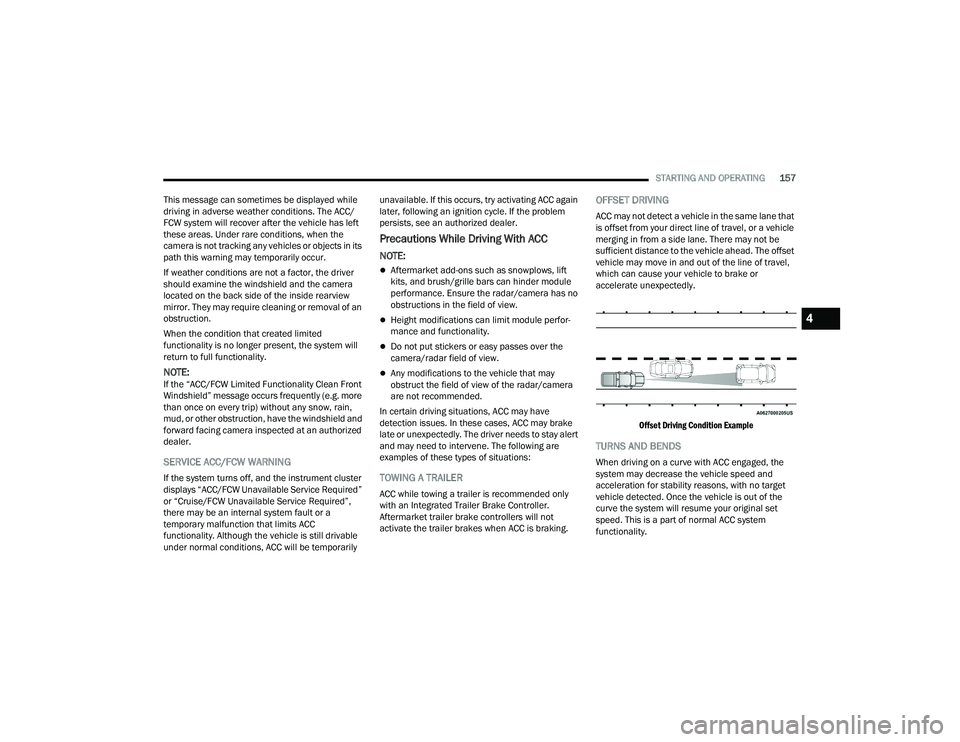
OFFSET DRIVING
ACC may not detect a vehicle in the same lane that
is offset from your direct line of travel, or a vehicle
merging in from a side lane. There may not be
sufficient distance to the vehicle ahead. The offset
vehicle may move in and out of the line of travel,
which can cause your vehicle to brake or
accelerate unexpectedly.
Offset Driving Condition Example
TURNS AND BENDS
When driving on a curve with ACC engaged, the
system may decrease the vehicle speed and
acceleration for stability reasons, with no target
vehicle detected. Once the vehicle is out of the
curve the system will resume your original set
speed. This is a part of normal ACC system
functionality.
4
23_DPF_OM_EN_USC_t.book Page 157
Page 168 of 444
166STARTING AND OPERATING
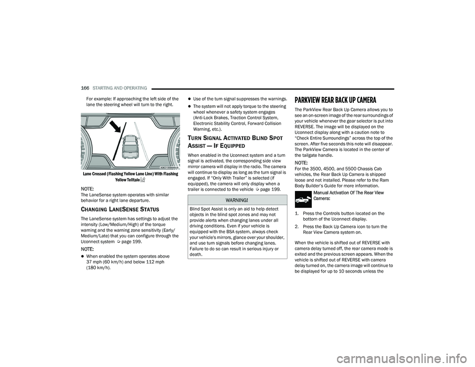
For example: If approaching the left side of the
lane the steering wheel will turn to the right.
Lane Crossed (Flashing Yellow Lane Line) With Flashing Yellow Telltale
NOTE:The LaneSense system operates with similar
behavior for a right lane departure.
CHANGING LANESENSE STATUS
The LaneSense system has settings to adjust the
intensity (Low/Medium/High) of the torque
warning and the warning zone sensitivity (Early/
Medium/Late) that you can configure through the
Uconnect system Ú page 199.
NOTE:
When enabled the system operates above
37 mph (60 km/h) and below 112 mph
(180 km/h).
Use of the turn signal suppresses the warnings.
The system will not apply torque to the steering
wheel whenever a safety system engages
(Anti-Lock Brakes, Traction Control System,
Electronic Stability Control, Forward Collision
Warning, etc.).
TURN SIGNAL ACTIVATED BLIND SPOT
A
SSIST — IF EQUIPPED
When enabled in the Uconnect system and a turn
signal is activated, the corresponding side view
mirror camera will display in the radio. The camera
will continue to display as long as the turn signal is
engaged. If “Only With Trailer” is selected (if
equipped), the camera will only display when a
trailer is connected to the vehicle Ú page 199.
PARKVIEW REAR BACK UP CAMERA
The ParkView Rear Back Up Camera allows you to
see an on-screen image of the rear surroundings of
your vehicle whenever the gear selector is put into
REVERSE. The image will be displayed on the
Uconnect display along with a caution note to
“Check Entire Surroundings” across the top of the
screen. After five seconds this note will disappear.
The ParkView Camera is located in the center of
the tailgate handle.
NOTE:For the 3500, 4500, and 5500 Chassis Cab
vehicles, the Rear Back Up Camera is shipped
loose and not installed. Please refer to the Ram
Body Builder’s Guide for more information.
Manual Activation Of The Rear View
Camera:
1. Press the Controls button located on the bottom of the Uconnect display.
2. Press the Back Up Camera icon to turn the Rear View Camera system on.
When the vehicle is shifted out of REVERSE with
camera delay turned off, the rear camera mode is
exited and the previous screen appears. When the
vehicle is shifted out of REVERSE with camera
delay turned on, the camera image will continue to
be displayed for up to 10 seconds unless the
WARNING!
Blind Spot Assist is only an aid to help detect
objects in the blind spot zones and may not
provide alerts when changing lanes under all
driving conditions. Even if your vehicle is
equipped with the BSA system, always check
your vehicle's mirrors, glance over your shoulder,
and use turn signals before changing lanes.
Failure to do so can result in serious injury or
death.
23_DPF_OM_EN_USC_t.book Page 166
Page 170 of 444
168STARTING AND OPERATING
NOTE:If snow, ice, mud, or any foreign substance builds
up on the camera lens, clean the lens, rinse with
water, and dry with a soft cloth. Do not cover the
lens.
Zoom View
When the Rear View Camera image is
being displayed, and the vehicle speed is
below 8 mph (13 km/h) while in any gear
selector position, Zoom View is available.
By pressing the “magnifying glass” icon in the
upper left of the display screen, the image will
zoom in to four times the standard view. Pressing
the icon a second time will return the view to the
standard Back Up Camera display.
When Zoom View is selected while the vehicle is in
REVERSE, then shifted to DRIVE, the camera delay
view will display the standard Back Up Camera view. If the vehicle is then returned to REVERSE
gear from DRIVE, the Zoom View selection will
automatically resume.
Shifting to NEUTRAL from any gear will maintain
the selected view (Zoom or Standard) as long as
the vehicle speed is below 8 mph (13 km/h).
If the vehicle is in PARK, Zoom View is available
until the gear selector is placed in DRIVE or
REVERSE.
NOTE:
If the vehicle is in DRIVE, NEUTRAL, or REVERSE,
and speed is greater than or equal to 8 mph
(13 km/h), Zoom View is unavailable and the
icon will appear gray.
While in Zoom View, the guidelines will not be
visible.
For information on Auxiliary Cameras (if equipped),
see Ú page 176.
SURROUND VIEW CAMERA SYSTEM —
IF EQUIPPED
Your vehicle may be equipped with the Surround
View Camera system that allows you to see an
on-screen image of the surroundings and Top View
of your vehicle whenever the gear selector is put
into REVERSE or manually activated via the
Uconnect system. The Top View of the vehicle will
show which doors are open. The image will be displayed on the touchscreen display along with a
caution note “Check Entire Surroundings” across
the top of the screen. After five seconds, this note
will disappear. The Surround View Camera system
is comprised of three sequential cameras located
in the front grille and side mirrors, in addition to a
fourth Rear Back Up Camera.
NOTE:
For the 3500, 4500, and 5500 Chassis Cab
vehicles, the Rear Back Up Camera is shipped
loose and not installed. Please refer to the Ram
Body Builder’s Guide for more information.
The Surround View Camera system has
programmable settings that may be selected
through the Uconnect system Ú
page 199.
Press this button on the touchscreen to
enter the Surround View Camera menu in
the Uconnect system.
When the vehicle is shifted into REVERSE, the Rear
View and Top View is the default view of the
system.
If the camera delay is turned on, the camera image
will display for up to 10 seconds after shifting out
of REVERSE. The camera image will not display for
10 seconds if the vehicle speed exceeds 8 mph
(13 km/h), the vehicle is shifted into PARK, or the
ignition is placed in the OFF position. The
touchscreen X button disables the display of the
camera image.
CAUTION!
To avoid vehicle damage, ParkView should
only be used as a parking aid. The ParkView
camera is unable to view every obstacle or
object in your drive path.
To avoid vehicle damage, the vehicle must be
driven slowly when using ParkView to be able
to stop in time when an obstacle is seen. It is
recommended that the driver look frequently
over his/her shoulder when using ParkView.
23_DPF_OM_EN_USC_t.book Page 168