Ram ProMaster 2018 Owner's Manual
Manufacturer: RAM, Model Year: 2018, Model line: ProMaster, Model: Ram ProMaster 2018Pages: 204, PDF Size: 4 MB
Page 11 of 204

INTERIOR
Interior
1 — Door Locks/Window Switches4 — Climate Controls
2 — Seats 5 — Switch Panel
3 — Gear Selector 6 — Glove Compartment
9
Page 12 of 204

10
Page 13 of 204

GETTING TO KNOW YOUR VEHICLE
KEYS......................12
KeyFob.....................12
SEATS .....................13
Heated Seats — If Equipped ........13
Adjustable Armrests — If Equipped ....14
HEAD RESTRAINTS..............14
Front Head Restraint Adjustment .....15
Front Head Restraint Removal .......15
STEERING WHEEL..............16
Telescoping Steering Column .......16
EXTERIOR LIGHTS..............16
Multifunction Lever ..............16
Headlights ...................17
High Beam/Low Beam Select Switch . . .17
Parking Lights .................17
Turn Signals ..................17
Lane Change Assist .............17
INTERIOR LIGHTS...............17
WIPERS AND WASHERS ..........17
Front Wiper Operation............17
CLIMATE CONTROLS.............19
Manual Climate Control Overview .....19
Climate Control Functions ..........22
Operating Tips .................23
HOOD......................24
Opening .....................24
Closing .....................24
INTERNAL EQUIPMENT ...........25
Power Outlets.................25
GETTING TO KNOW YOUR VEHICLE
11
Page 14 of 204
KEYS
Key Fob
Your vehicle uses a key start ignition system.
The ignition system consists of a key fob with
a Remote Keyless Entry (RKE) and an igni-
tion switch.
The key fob contains an integrated mechani-
cal key. To use the mechanical key, simply
push the mechanical key release button.
The vehicle is supplied with a code card
containing key code numbers to order dupli-
cate keys, and the authorized dealer that sold
you your new vehicle has the key code num-
bers for your vehicle locks. These numbers
can be used to order duplicate keys.Remote Keyless Entry (RKE)
This system allows you to lock or unlock the
doors from distances up to approximately
66 ft (20 m) using a hand-held key fob. The
key fob does not need to be pointed at the
vehicle to activate the system. NOTE:
The key fob may not be able to be detected by
the vehicle if it is located next to a mobile
phone, laptop or other electronic device;
these devices may block the key fob’s wire-
less signal.
To Unlock The Doors
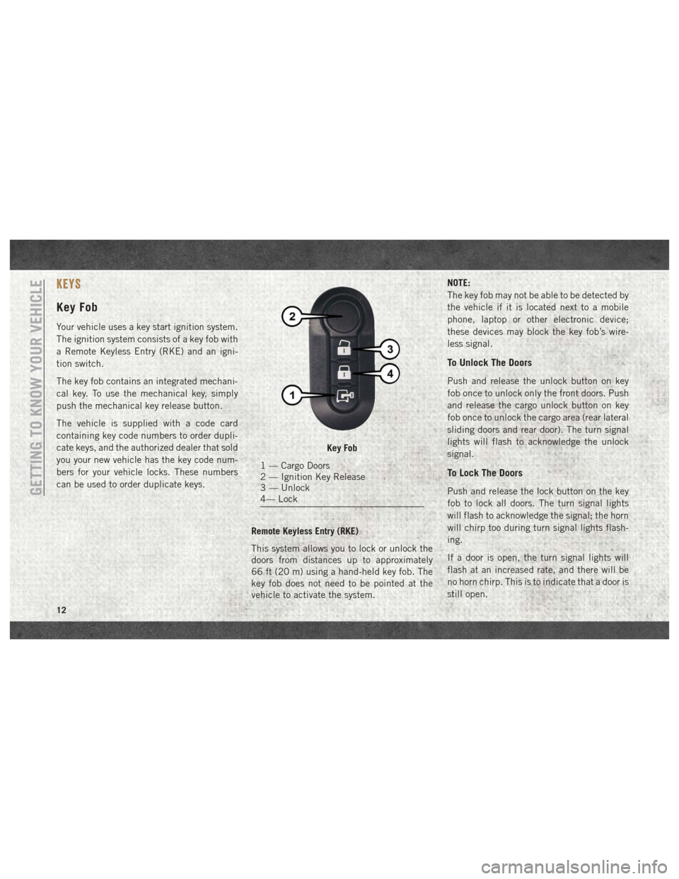
Push and release the unlock button on key
fob once to unlock only the front doors. Push
and release the cargo unlock button on key
fob once to unlock the cargo area (rear lateral
sliding doors and rear door). The turn signal
lights will flash to acknowledge the unlock
signal.
To Lock The Doors
Push and release the lock button on the key
fob to lock all doors. The turn signal lights
will flash to acknowledge the signal; the horn
will chirp too during turn signal lights flash-
ing.
If a door is open, the turn signal lights will
flash at an increased rate, and there will be
no horn chirp. This is to indicate that a door is
still open.
Key Fob
1 — Cargo Doors
2 — Ignition Key Release
3 — Unlock
4— Lock
GETTING TO KNOW YOUR VEHICLE
12
Page 15 of 204
Locking Doors With A Key
1. Insert the key with either side up.
2. Turn the key to the right to lock the door.
3. Turn the key to the left to unlock the door.
For maintenance procedures, refer to “Dealer
Service” in “Servicing And Maintenance” in
the Owner’s Manual at
www.mopar.com/en-us/
care/owners-manual.html (U.S. Residents) or
www.owners.mopar.ca (Canadian Residents).
General Information
The following regulatory statement applies to
all radio frequency (RF) devices equipped in
this vehicle:
This device complies with Part 15 of the FCC
Rules and with Industry Canada license-
exempt RSS standard(s). Operation is sub-
ject to the following two conditions:
1. This device may not cause harmful inter- ference, and
2. This device must accept any interference received, including interference that may
cause undesired operation. NOTE:
Changes or modifications not expressly ap-
proved by the party responsible for compli-
ance could void the user’s authority to oper-
ate the equipment.
SEATS
Seats are a part of the Occupant Restraint
System of the vehicle.
WARNING!
• It is dangerous to ride in a cargo area,
inside or outside of a vehicle. In a colli-
sion, people riding in these areas are
more likely to be seriously injured or
killed.
• Do not allow people to ride in any area of
your vehicle that is not equipped with
seats and seat belts. In a collision,
people riding in these areas are more
likely to be seriously injured or killed.
• Be sure everyone in your vehicle is in a
seat and using a seat belt properly.
Heated Seats — If Equipped
On some models, the front driver and passen-
ger seats may be equipped with heaters in
both the seat cushions and seatbacks. The
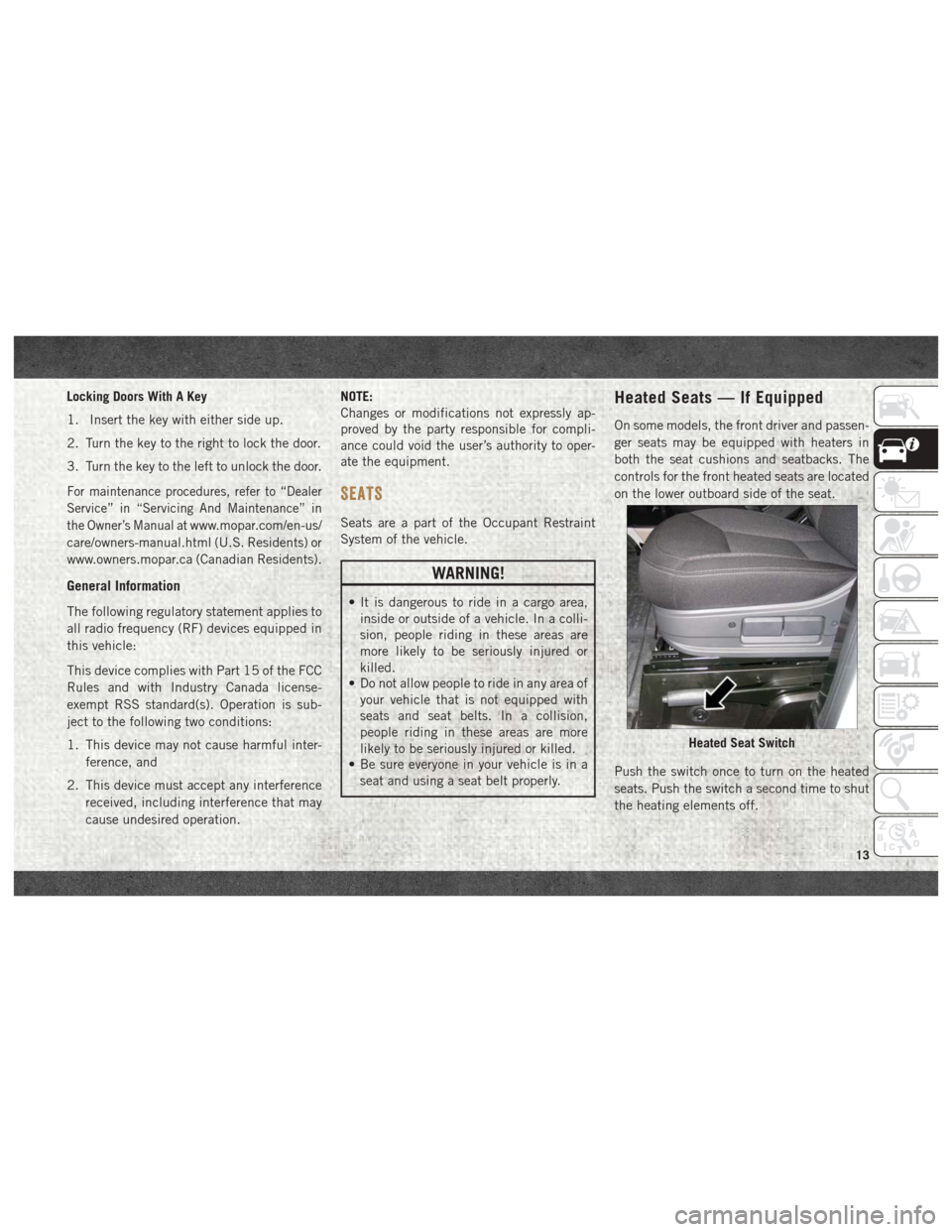
controls for the front heated seats are located
on the lower outboard side of the seat.
Push the switch once to turn on the heated
seats. Push the switch a second time to shut
the heating elements off.
Heated Seat Switch
13
Page 16 of 204
NOTE:
Once a heat setting is selected, heat will be
felt within two to five minutes.
WARNING!
• Persons who are unable to feel pain tothe skin because of advanced age,
chronic illness, diabetes, spinal cord in-
jury, medication, alcohol use, exhaus-
tion or other physical condition must
exercise care when using the seat
heater. It may cause burns even at low
temperatures, especially if used for long
periods of time
• Do not place anything on the seat or
seatback that insulates against heat,
such as a blanket or cushion. This may
cause the seat heater to overheat. Sit-
ting in a seat that has been overheated
could cause serious burns due to the
increased surface temperature of the
seat.
Adjustable Armrests —
If Equipped
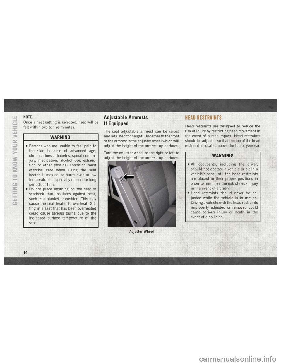
The seat adjustable armrest can be raised
and adjusted for height. Underneath the front
of the armrest is the adjuster wheel which will
adjust the height of the armrest up or down.
Turn the adjuster wheel to the right or left to
adjust the height of the armrest up or down.
HEAD RESTRAINTS
Head restraints are designed to reduce the
risk of injury by restricting head movement in
the event of a rear impact. Head restraints
should be adjusted so that the top of the head
restraint is located above the top of your ear.
WARNING!
• All occupants, including the driver,should not operate a vehicle or sit in a
vehicle’s seat until the head restraints
are placed in their proper positions in
order to minimize the risk of neck injury
in the event of a crash.
• Head restraints should never be ad-
justed while the vehicle is in motion.
Driving a vehicle with the head restraints
improperly adjusted or removed could
cause serious injury or death in the
event of a collision.
Adjuster Wheel
GETTING TO KNOW YOUR VEHICLE
14
Page 17 of 204
Front Head Restraint Adjustment
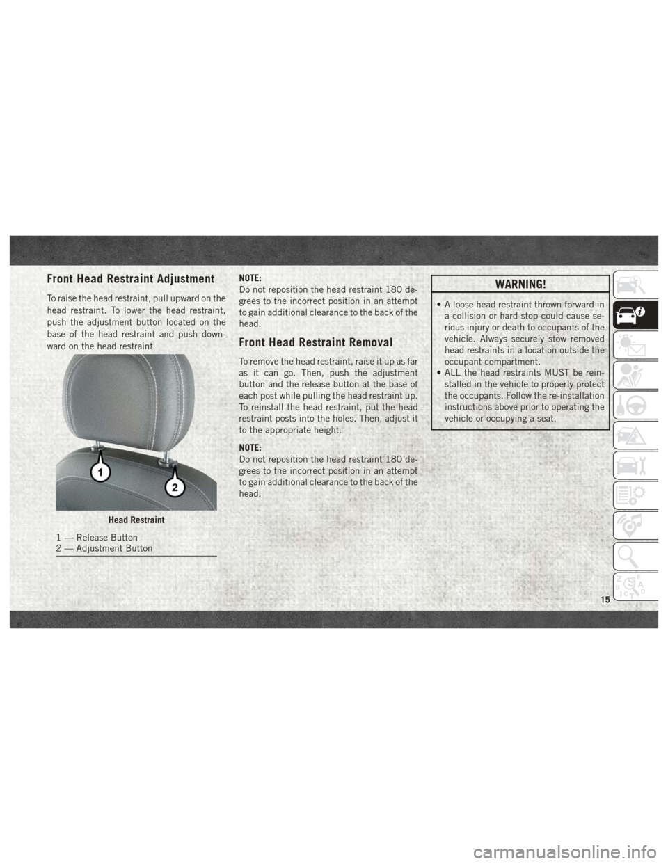
To raise the head restraint, pull upward on the
head restraint. To lower the head restraint,
push the adjustment button located on the
base of the head restraint and push down-
ward on the head restraint.NOTE:
Do not reposition the head restraint 180 de-
grees to the incorrect position in an attempt
to gain additional clearance to the back of the
head.
Front Head Restraint Removal
To remove the head restraint, raise it up as far
as it can go. Then, push the adjustment
button and the release button at the base of
each post while pulling the head restraint up.
To reinstall the head restraint, put the head
restraint posts into the holes. Then, adjust it
to the appropriate height.
NOTE:
Do not reposition the head restraint 180 de-
grees to the incorrect position in an attempt
to gain additional clearance to the back of the
head.
WARNING!
• A loose head restraint thrown forward in
a collision or hard stop could cause se-
rious injury or death to occupants of the
vehicle. Always securely stow removed
head restraints in a location outside the
occupant compartment.
• ALL the head restraints MUST be rein-
stalled in the vehicle to properly protect
the occupants. Follow the re-installation
instructions above prior to operating the
vehicle or occupying a seat.
Head Restraint
1 — Release Button
2 — Adjustment Button
15
Page 18 of 204
STEERING WHEEL
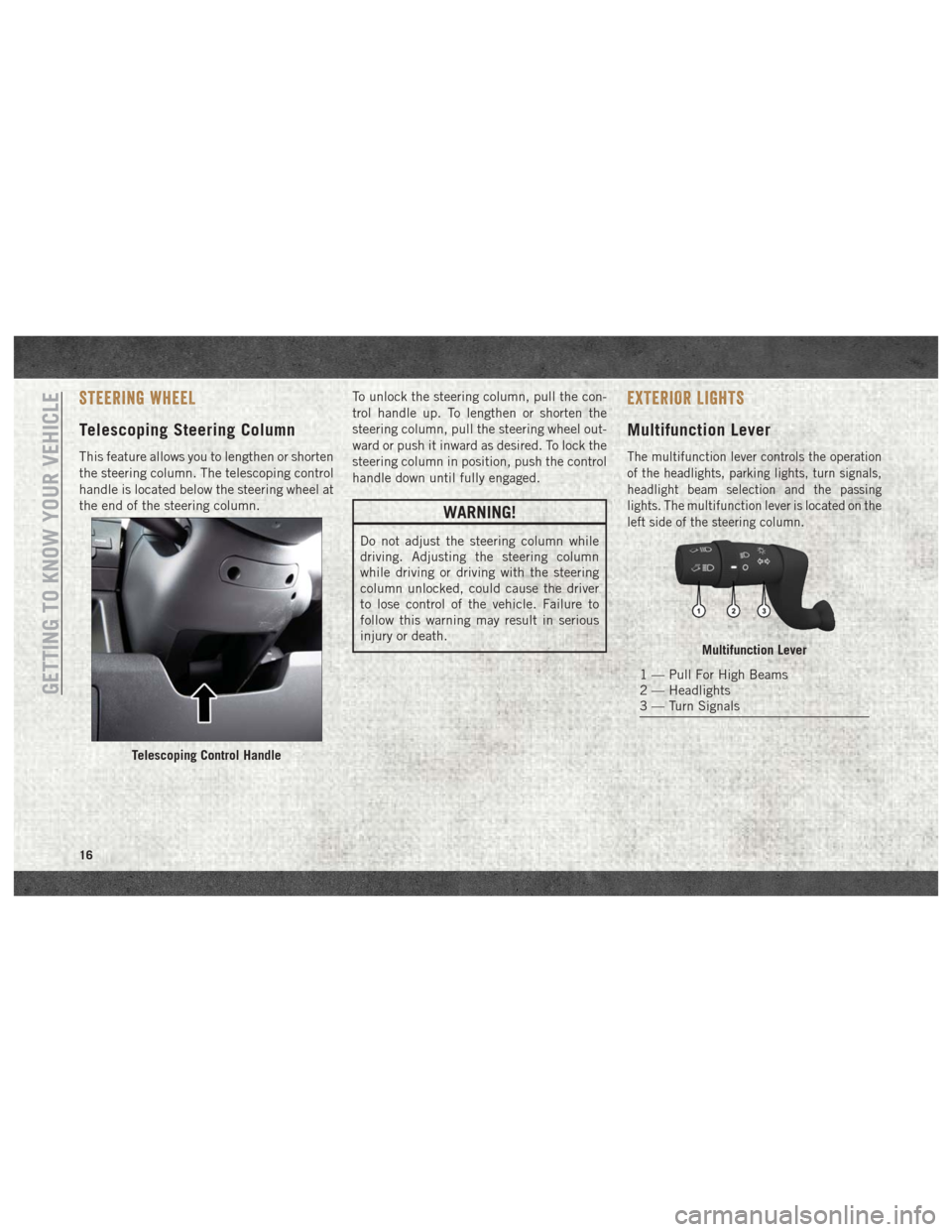
Telescoping Steering Column
This feature allows you to lengthen or shorten
the steering column. The telescoping control
handle is located below the steering wheel at
the end of the steering column.To unlock the steering column, pull the con-
trol handle up. To lengthen or shorten the
steering column, pull the steering wheel out-
ward or push it inward as desired. To lock the
steering column in position, push the control
handle down until fully engaged.
WARNING!
Do not adjust the steering column while
driving. Adjusting the steering column
while driving or driving with the steering
column unlocked, could cause the driver
to lose control of the vehicle. Failure to
follow this warning may result in serious
injury or death.
EXTERIOR LIGHTS
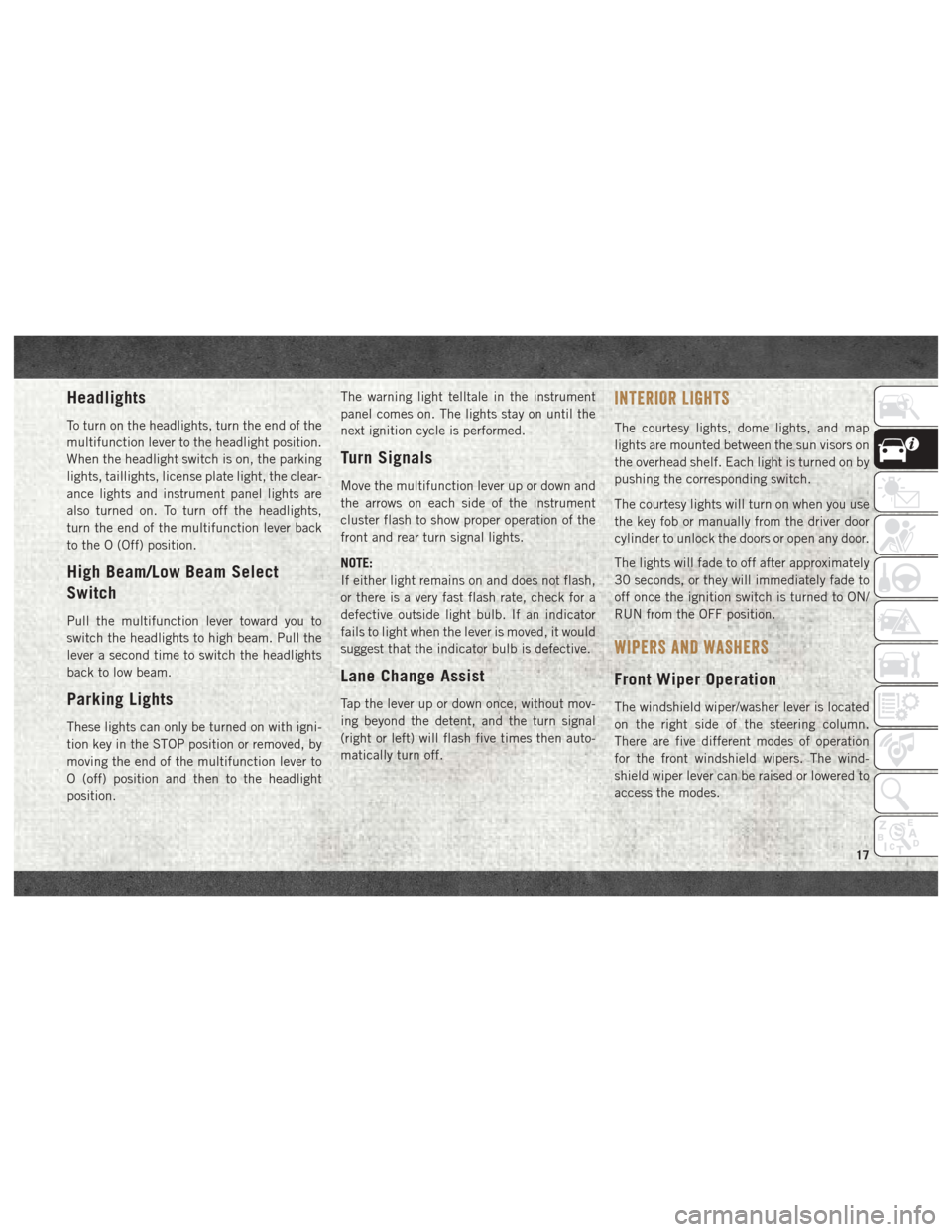
Multifunction Lever
The multifunction lever controls the operation
of the headlights, parking lights, turn signals,
headlight beam selection and the passing
lights. The multifunction lever is located on the
left side of the steering column.
Telescoping Control Handle
Multifunction Lever
1 — Pull For High Beams
2 — Headlights
3 — Turn Signals
GETTING TO KNOW YOUR VEHICLE
16
Page 19 of 204
Headlights
To turn on the headlights, turn the end of the
multifunction lever to the headlight position.
When the headlight switch is on, the parking
lights, taillights, license plate light, the clear-
ance lights and instrument panel lights are
also turned on. To turn off the headlights,
turn the end of the multifunction lever back
to the O (Off) position.
High Beam/Low Beam Select
Switch
Pull the multifunction lever toward you to
switch the headlights to high beam. Pull the
lever a second time to switch the headlights
back to low beam.
Parking Lights
These lights can only be turned on with igni-
tion key in the STOP position or removed, by
moving the end of the multifunction lever to
O (off) position and then to the headlight
position.The warning light telltale in the instrument
panel comes on. The lights stay on until the
next ignition cycle is performed.
Turn Signals
Move the multifunction lever up or down and
the arrows on each side of the instrument
cluster flash to show proper operation of the
front and rear turn signal lights.
NOTE:
If either light remains on and does not flash,
or there is a very fast flash rate, check for a
defective outside light bulb. If an indicator
fails to light when the lever is moved, it would
suggest that the indicator bulb is defective.
Lane Change Assist
Tap the lever up or down once, without mov-
ing beyond the detent, and the turn signal
(right or left) will flash five times then auto-
matically turn off.
INTERIOR LIGHTS
The courtesy lights, dome lights, and map
lights are mounted between the sun visors on
the overhead shelf. Each light is turned on by
pushing the corresponding switch.
The courtesy lights will turn on when you use
the key fob or manually from the driver door
cylinder to unlock the doors or open any door.
The lights will fade to off after approximately
30 seconds, or they will immediately fade to
off once the ignition switch is turned to ON/
RUN from the OFF position.
WIPERS AND WASHERS
Front Wiper Operation
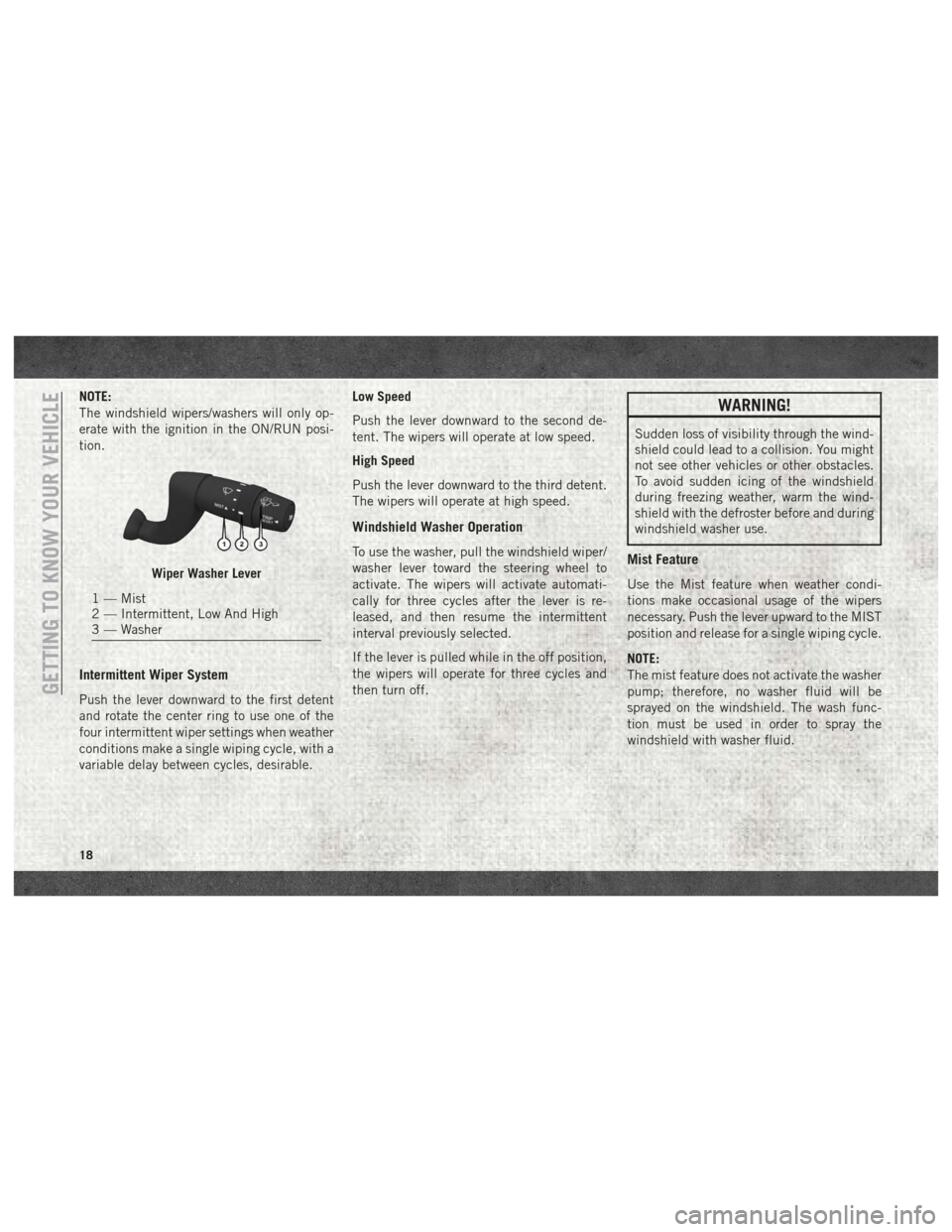
The windshield wiper/washer lever is located
on the right side of the steering column.
There are five different modes of operation
for the front windshield wipers. The wind-
shield wiper lever can be raised or lowered to
access the modes.
17
Page 20 of 204
NOTE:
The windshield wipers/washers will only op-
erate with the ignition in the ON/RUN posi-
tion.
Intermittent Wiper System
Push the lever downward to the first detent
and rotate the center ring to use one of the
four intermittent wiper settings when weather
conditions make a single wiping cycle, with a
variable delay between cycles, desirable.Low Speed
Push the lever downward to the second de-
tent. The wipers will operate at low speed.
High Speed
Push the lever downward to the third detent.
The wipers will operate at high speed.
Windshield Washer Operation
To use the washer, pull the windshield wiper/
washer lever toward the steering wheel to
activate. The wipers will activate automati-
cally for three cycles after the lever is re-
leased, and then resume the intermittent
interval previously selected.
If the lever is pulled while in the off position,
the wipers will operate for three cycles and
then turn off.
WARNING!
Sudden loss of visibility through the wind-
shield could lead to a collision. You might
not see other vehicles or other obstacles.
To avoid sudden icing of the windshield
during freezing weather, warm the wind-
shield with the defroster before and during
windshield washer use.
Mist Feature
Use the Mist feature when weather condi-
tions make occasional usage of the wipers
necessary. Push the lever upward to the MIST
position and release for a single wiping cycle.
NOTE:
The mist feature does not activate the washer
pump; therefore, no washer fluid will be
sprayed on the windshield. The wash func-
tion must be used in order to spray the
windshield with washer fluid.Wiper Washer Lever
1 — Mist
2 — Intermittent, Low And High
3 — Washer
GETTING TO KNOW YOUR VEHICLE
18