radio Ram ProMaster 2018 User Guide
[x] Cancel search | Manufacturer: RAM, Model Year: 2018, Model line: ProMaster, Model: Ram ProMaster 2018Pages: 204, PDF Size: 4 MB
Page 2 of 204

This guide has been prepared to help you get quickly acquainted with your new RAM brand vehicle
and to provide a convenient reference source for common questions. Howev\
er, it is not a substitute for your Owner’s Manual.
For complete operational instructions, maintenance procedures and import\
ant safety messages, please consult your Owner’s Manual, Navigation/Uconnect manuals found on the website on the back c\
over and
other Warning Labels in your vehicle.
Not all features shown in this guide may apply to your vehicle. For additional information on accessories
to help personalize your vehicle, visit www.mopar.com (U.S.), www.mopar.ca (Canada) or your local
RAM brand dealer.
DRIVING AND ALCOHOL
Drunken driving is one of the most frequent causes of collisions. Your driving ability can
be seriously impaired with blood alcohol levels far below the legal mini\
mum. If you are drinking, don’t
drive. Ride with a designated non-drinking driver, call a cab, a friend, or use public transportation.
WARNING
Driving after drinking can lead to a collision. Your perceptions are less sharp, your reflexes are slower,
and your judgment is impaired when you have been drinking. Never drink a\
nd then drive.
IMPORTANT
Get warranty and other information online – you can review and print \
or download a copy of the Owner’s Manual, Navigation/Uconnect manuals and the limited warranties provided by FCA US LLC for your
vehicle by visiting www.mopar.com (U.S.) or www.owners.mopar.ca (Canada). Click on the applicable
link in the “Popular Topics” area of the www.mopar.com (U.S.) or www.owners.mopar.ca (Canada)
homepage and follow the instructions to select the applicable year, make and model of your vehicle.
This User Guide is intended to familiarize you with the important featur\
es of your vehicle. Your Owner’s Manual, Navigation/Uconnect manuals and Warranty Booklet can be found by visiting the website on the
back cover of your User Guide. We hope you find these resources useful. U.S. residents can purchase
replacement kits by visiting www.techauthority.com and Canadian residents can purchase replacement
kits by calling 1 800 387-1143.
The driver’s primary responsibility is the safe operation of the vehicle. Driving while distracted can result in loss of vehicle control, resulting in a collision and personal injury. FCA US LLC strongly recommends that the
driver use extreme caution when using any device or feature that may tak\
e their attention off the road. Use of
any electrical devices, such as cellular telephones, computers, portable\
radios, vehicle navigation or other devices, by the driver while the vehicle is moving is dangerous and coul\
d lead to a serious collision. Texting while driving is also dangerous and should never be done while the vehic\
le is moving. If you find yourself
unable to devote your full attention to vehicle operation, pull off the \
road to a safe location and stop your
vehicle. Some states or provinces prohibit the use of cellular telephone\
s or texting while driving. It is always the driver’s responsibility to comply with all local laws.
3110991_18b_Ram_ProMaster_UG_070717.indd 27/7/17 10:05 AM
Page 10 of 204
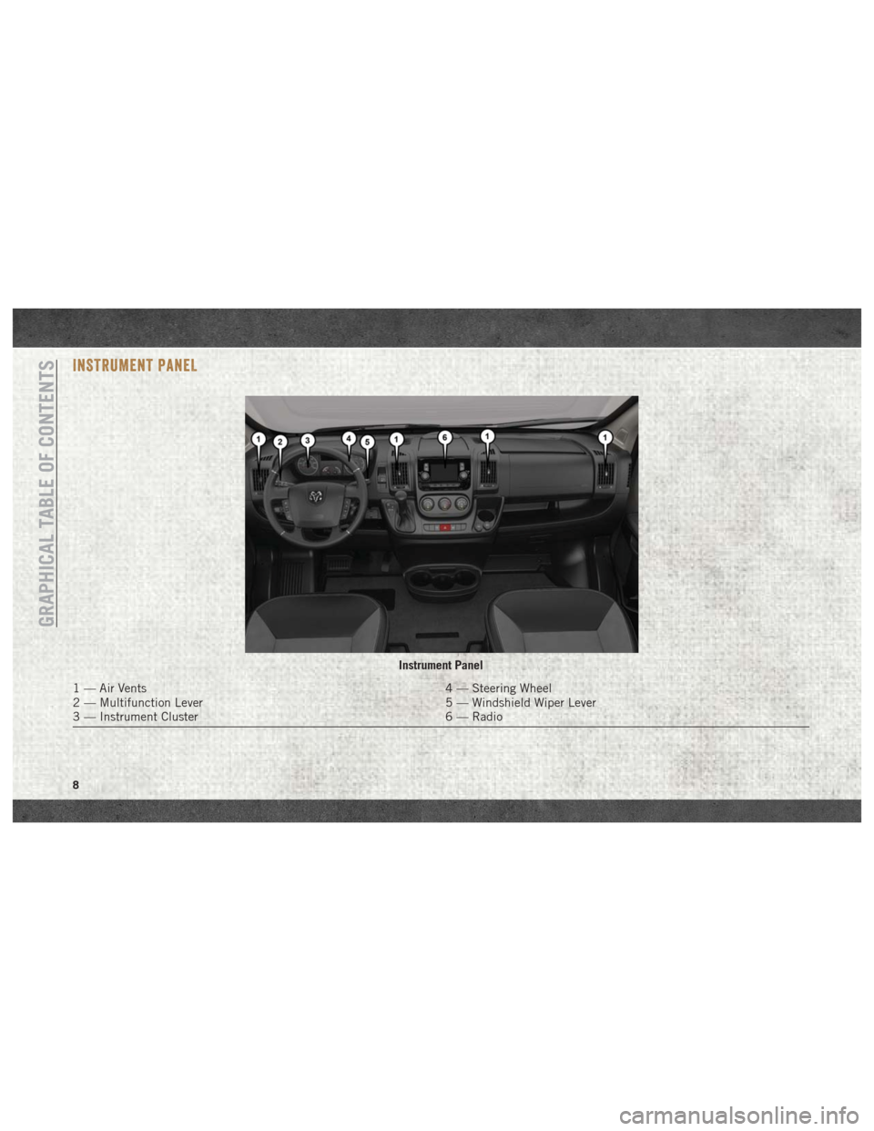
INSTRUMENT PANEL
Instrument Panel
1 — Air Vents4 — Steering Wheel
2 — Multifunction Lever 5 — Windshield Wiper Lever
3 — Instrument Cluster 6 — Radio
GRAPHICAL TABLE OF CONTENTS
8
Page 15 of 204
Locking Doors With A Key
1. Insert the key with either side up.
2. Turn the key to the right to lock the door.
3. Turn the key to the left to unlock the door.
For maintenance procedures, refer to “Dealer
Service” in “Servicing And Maintenance” in
the Owner’s Manual at
www.mopar.com/en-us/
care/owners-manual.html (U.S. Residents) or
www.owners.mopar.ca (Canadian Residents).
General Information
The following regulatory statement applies to
all radio frequency (RF) devices equipped in
this vehicle:
This device complies with Part 15 of the FCC
Rules and with Industry Canada license-
exempt RSS standard(s). Operation is sub-
ject to the following two conditions:
1. This device may not cause harmful inter- ference, and
2. This device must accept any interference received, including interference that may
cause undesired operation. NOTE:
Changes or modifications not expressly ap-
proved by the party responsible for compli-
ance could void the user’s authority to oper-
ate the equipment.
SEATS
Seats are a part of the Occupant Restraint
System of the vehicle.
WARNING!
• It is dangerous to ride in a cargo area,
inside or outside of a vehicle. In a colli-
sion, people riding in these areas are
more likely to be seriously injured or
killed.
• Do not allow people to ride in any area of
your vehicle that is not equipped with
seats and seat belts. In a collision,
people riding in these areas are more
likely to be seriously injured or killed.
• Be sure everyone in your vehicle is in a
seat and using a seat belt properly.
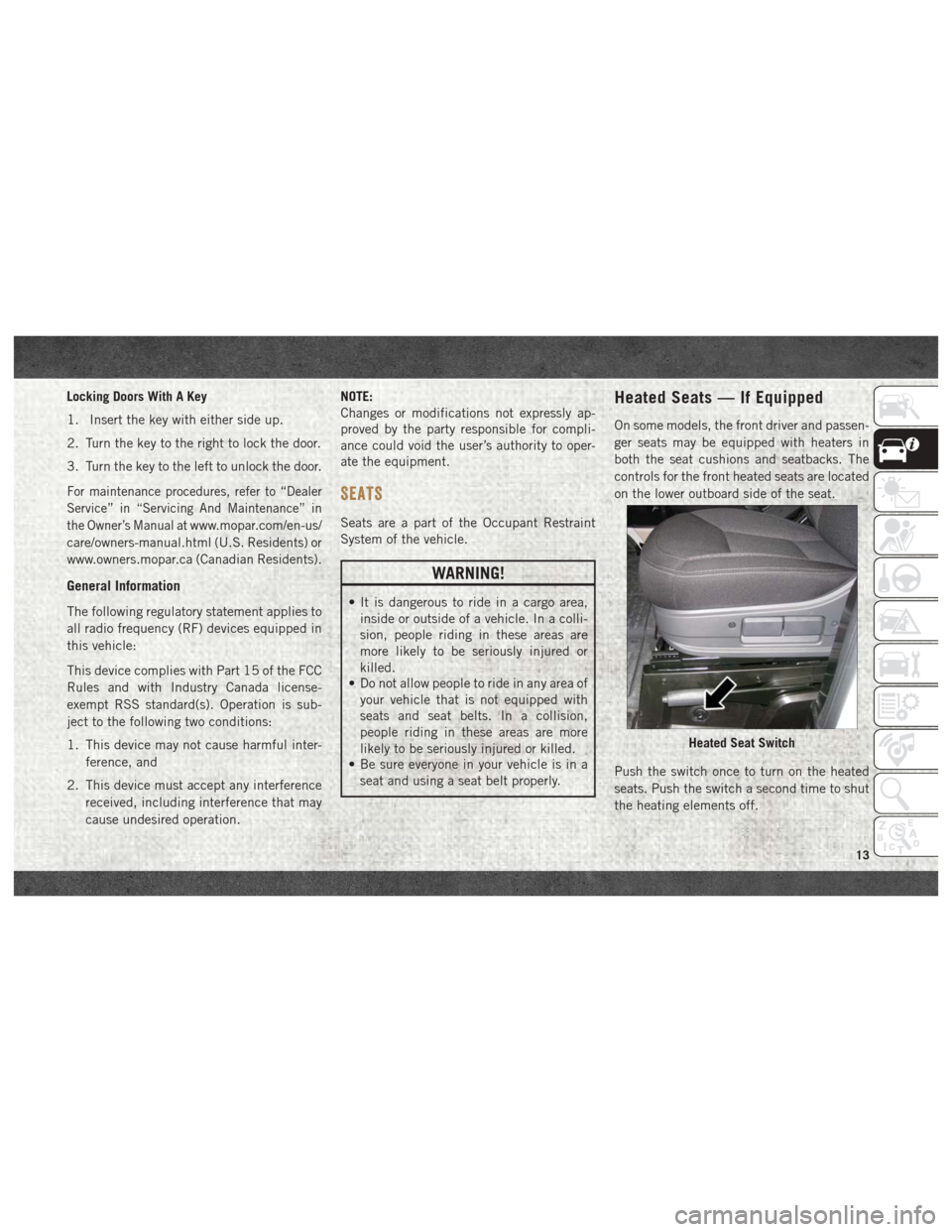
Heated Seats — If Equipped
On some models, the front driver and passen-
ger seats may be equipped with heaters in
both the seat cushions and seatbacks. The
controls for the front heated seats are located
on the lower outboard side of the seat.
Push the switch once to turn on the heated
seats. Push the switch a second time to shut
the heating elements off.
Heated Seat Switch
13
Page 21 of 204
CLIMATE CONTROLS
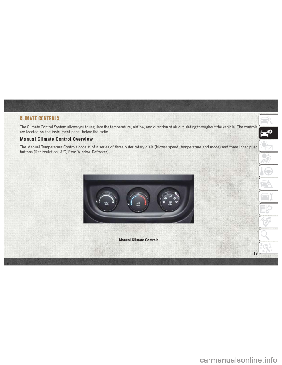
The Climate Control System allows you to regulate the temperature, airflow, and direction of air circulating throughout the vehicle. The controls
are located on the instrument panel below the radio.
Manual Climate Control Overview
The Manual Temperature Controls consist of a series of three outer rotary dials (blower speed, temperature and mode) and three inner push
buttons (Recirculation, A/C, Rear Window Defroster).
Manual Climate Controls
19
Page 32 of 204
INSTRUMENT CLUSTER DISPLAY
Your vehicle may be equipped with an instru-
ment cluster display, which offers useful in-
formation to the driver. With the ignition in
the STOP/OFF mode, opening/closing of a
door will activate the display for viewing, and
display the total miles, or kilometers, in the
odometer. Your instrument cluster display is
designed to display important information
about your vehicle’s systems and features.
Using a driver interactive display located on
the instrument panel, your instrument clus-
ter display can show you how systems are
working and give you warnings when they are
not. The steering wheel mounted controls
allow you to scroll through the main menus
and submenus. You can access the specific
information you want and make selections
and adjustments.
Location And Controls
The instrument cluster display features a
driver-interactive display that is located in
the instrument cluster.This system allows the driver to select a
variety of useful information by pushing the
switches mounted on the instrument panel.
Examples of menu items are:
• Speed Beep
• Buzzer Volume
• Seat Belt Buzzer (Just Available After SBR
Disable Made By CHR Service)
• Service (Diesel Only)
• Exit Menu
If equipped with a Uconnect system, some
customer programmable features will
display in the radio. Refer to the “Uconnect
Settings” in “Multimedia” in the Owner’s
Manual at
www.mopar.com/en-us/care/
owners-manual.html (U.S. Residents) or
www.owners.mopar.ca (Canadian Residents)
for further information.
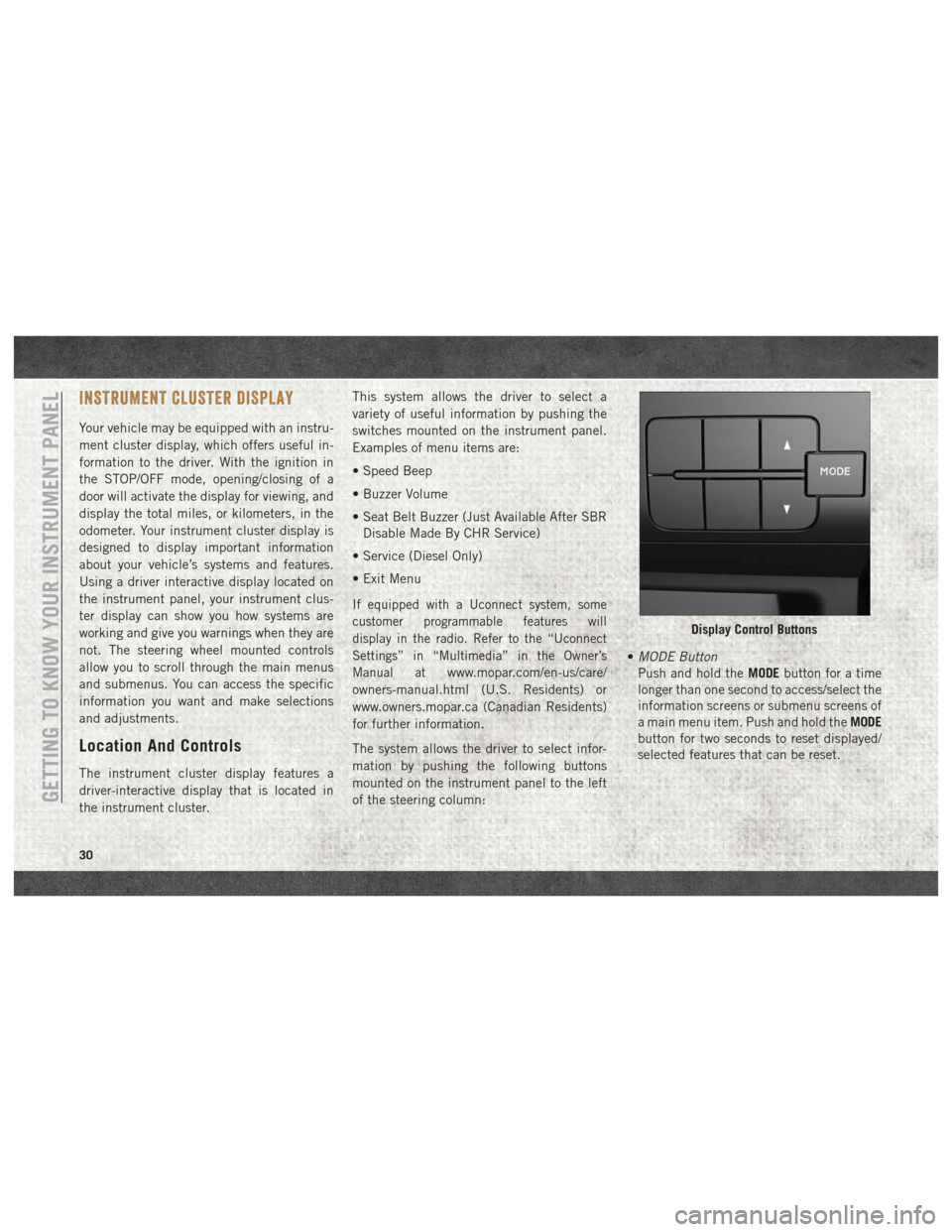
The system allows the driver to select infor-
mation by pushing the following buttons
mounted on the instrument panel to the left
of the steering column: •
MODE Button
Push and hold the MODEbutton for a time
longer than one second to access/select the
information screens or submenu screens of
a main menu item. Push and hold the MODE
button for two seconds to reset displayed/
selected features that can be reset.
Display Control Buttons
GETTING TO KNOW YOUR INSTRUMENT PANEL
30
Page 48 of 204
Tire Pressure Monitoring Low Pressure
Warnings
The Tire Pressure Monitoring Telltale Light
will illuminate in the instrument cluster, an
audible chime will be activated, and the
“Check tire pressure” text message will dis-
play when one or more of the four active road
tire pressures are low. Should this occur, you
should stop as soon as possible, check the
inflation pressure of each tire on your vehicle,
and inflate each tire to the vehicle’s recom-
mended cold placard pressure value. The
system will automatically update and the Tire
Pressure Monitoring Light will extinguish
once the updated tire pressures have been
received. The vehicle may need to be driven
for up to 20 minutes above 15 mph
(24 km/h) to receive this information.
Check TPMS Warnings
The Tire Pressure Monitoring Telltale Light
will flash on and off for 75 seconds and
remain on solid when a system fault is de-
tected, an audible chime will be activated
and the “Tire Pressure Monitoring Unavail-
able” text message will display. If the ignition
key is cycled, this sequence will repeat pro-viding the system fault still exists. The Tire
Pressure Monitoring Telltale Light will turn
off when the fault condition no longer exists.
A system fault can occur with any of the
following scenarios:
1. Jamming due to electronic devices or driv-
ing next to facilities emitting the same
radio frequencies as the TPM sensors.
2. Installing some form of aftermarket win- dow tinting that affects radio wave
signals.
3. Snow or ice around the wheels or wheel housings.
4. Using tire chains on the vehicle.
5. Using wheels/tires not equipped with TPM sensors.
NOTE:
Your vehicle is equipped with a regular size
spare wheel.
1. The spare tire has a tire pressure monitor- ing sensor, but it is not monitored until it
is mounted in place of any of the existing
four road tires. 2. If you install the spare tire in place of a
road tire that has a pressure below the
low-pressure warning limit, upon the next
ignition key cycle, a chime will sound and
the Tire Pressure Monitoring Telltale Light
will turn ON due to the low tire condition.
Then, after driving the vehicle for up to
20 minutes above 15 mph (24 km/h), the
system will recognize the new sensor, and
turn off the telltale.
3. If a spare tire not equipped with tire pressure monitoring sensor is used, then
the Tire Pressure Monitoring Telltale Light
will turn ON, flashing for 75 seconds and
then remaining solid for each subsequent
ignition key cycle.
NOTE:
For correct Tire Pressure Monitoring behavior,
please wait for about 20 minutes in key-off
during each tire substitution.
SAFETY
46
Page 91 of 204
SPEED CONTROL
When engaged, the Speed Control takes over
accelerator operations at speeds greater than
25 mph (40 km/h) up to the maximum speed
of 100 mph (160 km/h).
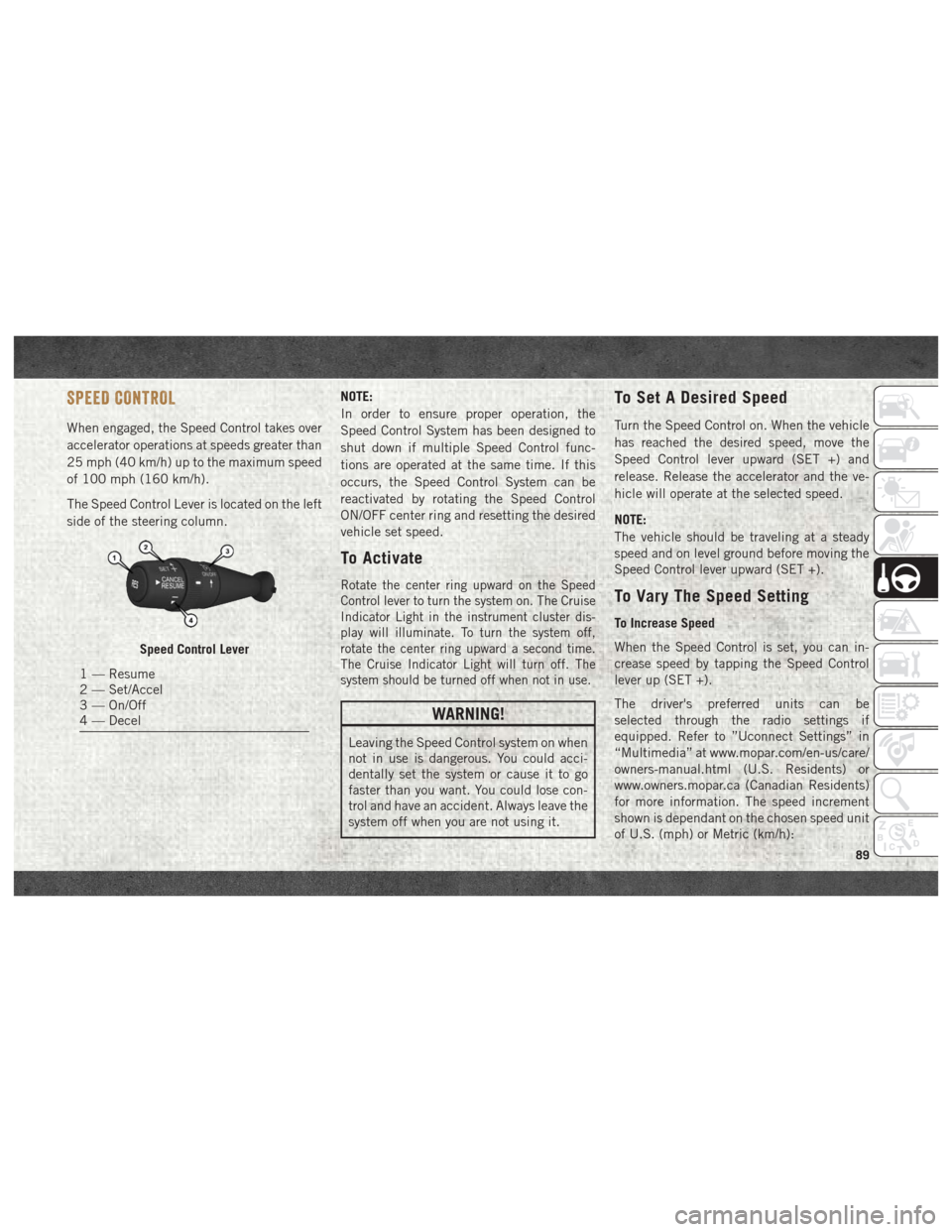
The Speed Control Lever is located on the left
side of the steering column.NOTE:
In order to ensure proper operation, the
Speed Control System has been designed to
shut down if multiple Speed Control func-
tions are operated at the same time. If this
occurs, the Speed Control System can be
reactivated by rotating the Speed Control
ON/OFF center ring and resetting the desired
vehicle set speed.
To Activate
Rotate the center ring upward on the Speed
Control lever to turn the system on. The Cruise
Indicator Light in the instrument cluster dis-
play will illuminate. To turn the system off,
rotate the center ring upward a second time.
The Cruise Indicator Light will turn off. The
system should be turned off when not in use.
WARNING!
Leaving the Speed Control system on when
not in use is dangerous. You could acci-
dentally set the system or cause it to go
faster than you want. You could lose con-
trol and have an accident. Always leave the
system off when you are not using it.
To Set A Desired Speed
Turn the Speed Control on. When the vehicle
has reached the desired speed, move the
Speed Control lever upward (SET +) and
release. Release the accelerator and the ve-
hicle will operate at the selected speed.
NOTE:
The vehicle should be traveling at a steady
speed and on level ground before moving the
Speed Control lever upward (SET +).
To Vary The Speed Setting
To Increase Speed
When the Speed Control is set, you can in-
crease speed by tapping the Speed Control
lever up (SET +).
The driver's preferred units can be
selected through the radio settings if
equipped. Refer to ”Uconnect Settings” in
“Multimedia” at www.mopar.com/en-us/care/
owners-manual.html (U.S. Residents) or
www.owners.mopar.ca (Canadian Residents)
for more information. The speed increment
shown is dependant on the chosen speed unit
of U.S. (mph) or Metric (km/h):
Speed Control Lever
1 — Resume
2 — Set/Accel
3 — On/Off
4 — Decel
89
Page 92 of 204
U.S. Speed (mph)
• Tapping the Speed Control lever up (SET +)once will result in a 1 mph increase in set
speed. Each subsequent tap of the lever
results in an increase of 1 mph.
• If the lever is continually held up, the set speed will continue to increase until the
lever is released, then the new set speed
will be established.
Metric Speed (km/h)
• Tapping the Speed Control lever up (SET +) once will result in a 1 km/h increase in set
speed. Each subsequent tap of the lever
results in an increase of 1 km/h.
• If the lever is continually held up, the set speed will continue to increase until the
lever is released, then the new set speed
will be established.
To Decrease Speed
When the Speed Control is set, you can de-
crease speed by tapping the Speed Control
lever down (-). The driver's preferred units can be
selected through the radio settings if
equipped. Refer to ”Uconnect Settings” in
“Multimedia” at www.mopar.com/en-us/care/
owners-manual.html (U.S. Residents) or
www.owners.mopar.ca (Canadian Residents)
for more information. The speed increment
shown is dependant on the chosen speed unit
of U.S. (mph) or Metric (km/h):
U.S. Speed (mph)
• Tapping the Speed Control lever down (-)
once will result in a 1 mph decrease in set
speed. Each subsequent tap of the lever
results in a decrease of 1 mph.
• If the lever is continually held down, the set speed will continue to decrease until the
lever is released, then the new set speed
will be established.
Metric Speed (km/h)
• Tapping the Speed Control lever down (-) once will result in a 1 km/h decrease in set
speed. Each subsequent tap of the lever
results in a decrease of 1 km/h. • If the lever is continually held down, the set
speed will continue to decrease until the
lever is released, then the new set speed
will be established.
To Accelerate For Passing
Press the accelerator as you would normally.
When the pedal is released, the vehicle will
return to the set speed.
Using Speed Control On Hills
The transmission may downshift on hills to
maintain the vehicle set speed.
NOTE:
The Speed Control system maintains speed
up and down hills. A slight speed change on
moderate hills is normal.
On steep hills, a greater speed loss or gain
may occur so it may be preferable to drive
without Speed Control.
WARNING!
Speed Control can be dangerous where the
system cannot maintain a constant speed.
Your vehicle could go too fast for the con-
STARTING AND OPERATING
90
Page 118 of 204
WARNING!
Do not attempt jump starting if the battery
is frozen. It could rupture or explode and
cause personal injury.
CAUTION!
Do not use a portable battery booster pack
or any other booster source with a system
voltage greater than 12 Volts or damage to
the battery, starter motor, alternator or
electrical system may occur.
Preparations For Jump Start
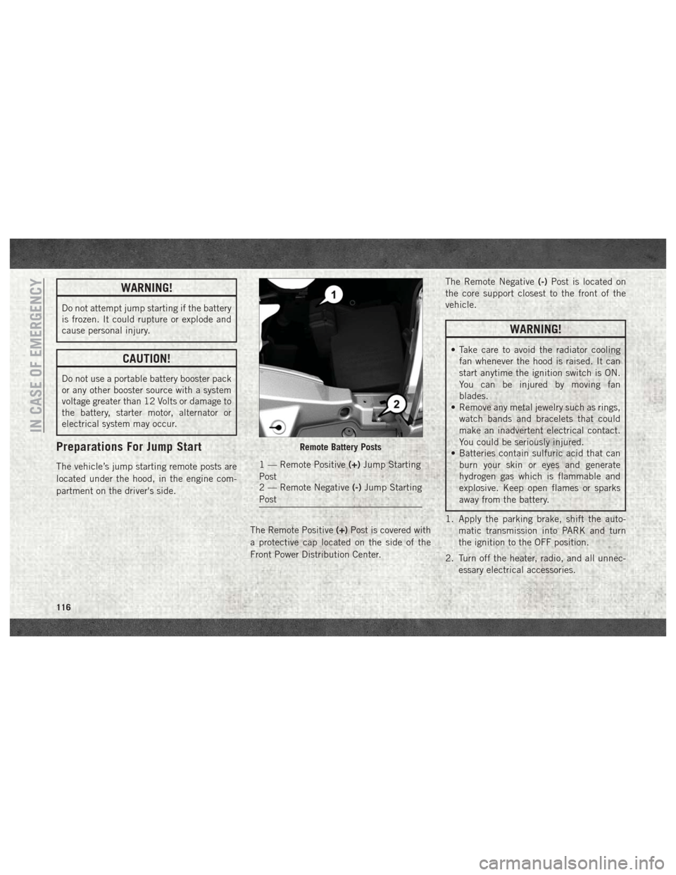
The vehicle’s jump starting remote posts are
located under the hood, in the engine com-
partment on the driver's side.The Remote Positive(+)Post is covered with
a protective cap located on the side of the
Front Power Distribution Center. The Remote Negative
(-)Post is located on
the core support closest to the front of the
vehicle.
WARNING!
• Take care to avoid the radiator cooling fan whenever the hood is raised. It can
start anytime the ignition switch is ON.
You can be injured by moving fan
blades.
• Remove any metal jewelry such as rings,
watch bands and bracelets that could
make an inadvertent electrical contact.
You could be seriously injured.
• Batteries contain sulfuric acid that can
burn your skin or eyes and generate
hydrogen gas which is flammable and
explosive. Keep open flames or sparks
away from the battery.
1. Apply the parking brake, shift the auto- matic transmission into PARK and turn
the ignition to the OFF position.
2. Turn off the heater, radio, and all unnec- essary electrical accessories.
Remote Battery Posts
1 — Remote Positive (+)Jump Starting
Post
2 — Remote Negative (-)Jump Starting
Post
IN CASE OF EMERGENCY
116
Page 163 of 204
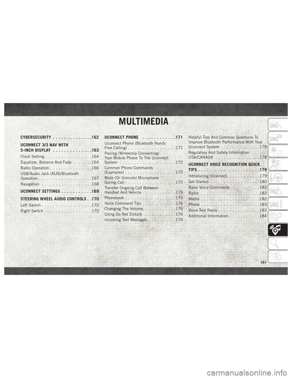
MULTIMEDIA
CYBERSECURITY..............162
UCONNECT 3/3 NAV WITH
5-INCH DISPLAY ..............163
Clock Setting.................164
Equalizer, Balance And Fade .......164
Radio Operation ...............166
USB/Audio Jack (AUX)/Bluetooth
Operation ...................167
Navigation ..................168
UCONNECT SETTINGS ...........169
STEERING WHEEL AUDIO CONTROLS . .170
Left Switch ..................170
Right Switch .................170
UCONNECT PHONE ............171
Uconnect Phone (Bluetooth Hands
Free Calling).................171
Pairing (Wirelessly Connecting)
Your Mobile Phone To The Uconnect
System ....................172
Common Phone Commands
(Examples) ..................175
Mute (Or Unmute) Microphone
During Call ..................175
Transfer Ongoing Call Between
Handset And Vehicle ............175
Phonebook ..................175
Voice Command Tips ............176
Changing The Volume ............176
Using Do Not Disturb ...........176
Incoming Text Messages ..........176Helpful Tips And Common Questions To
Improve Bluetooth Performance With Your
Uconnect System
..............178
Regulatory And Safety Information
USA/CANADA ................178
UCONNECT VOICE RECOGNITION QUICK
TIPS..................... .179
Introducing Uconnect............179
Get Started ..................180
Basic Voice Commands ...........182
Radio .....................182
Media .....................182
Phone .....................183
Voice Text Reply ...............183
Additional Information ...........184
MULTIMEDIA
161