battery Ram ProMaster 2018 User Guide
[x] Cancel search | Manufacturer: RAM, Model Year: 2018, Model line: ProMaster, Model: Ram ProMaster 2018Pages: 204, PDF Size: 4 MB
Page 29 of 204
WARNING!
To avoid serious injury or death:
• Only devices designed for use in thistype of outlet should be inserted into any
12 Volt outlet.
• Do not touch with wet hands.
• Close the lid when not in use and while
driving the vehicle.
• If this outlet is mishandled, it may cause
an electric shock and failure.
CAUTION!
• Many accessories that can be plugged indraw power from the vehicle's battery,
even when not in use (i.e., cellular
phones, etc.). Eventually, if plugged in
long enough, the vehicle's battery will
discharge sufficiently to degrade battery
life and/or prevent the engine from start-
ing.
• Accessories that draw higher power (i.e.,
coolers, vacuum cleaners, lights, etc.)
will degrade the battery even more
CAUTION!
quickly. Only use these intermittently
and with greater caution.
• After the use of high power draw acces-
sories, or long periods of the vehicle not
being started (with accessories still
plugged in), the vehicle must be driven a
sufficient length of time to allow the
generator to recharge the vehicle's bat-
tery.
27
Page 35 of 204

Electronic Park Brake (EPB) Messages
The following EPB messages will appear in the Instrument Cluster Display.
MessageDescription
Service Electronic Parking Brake This message indicates that the Electronic Parking Brake is in fault. If
the parking brake does not engage, the parked vehicle should be shifted
into a gear and the wheels chocked to prevent rolling.
Contact your authorized dealer if the message continues to appear.
Park Brake Temporarily Unavailable This message indicates that the Electronic Parking Brake is temporarily
unavailable (for example due to battery voltage out of range).
If the parking brake does not engage , the parked vehicle should be
shifted into a gear and the wheels chocked to prevent rolling.
Contact your authorized dealer if the message continues to appear.
Automatic Park Brake Temporarily Unavailable This message indicates that Electronic Parking Brake automatic fea-
tures are temporarily unavailable.
If the parking brake does not engage , the parked vehicle should be
shifted into a gear and the wheels chocked to prevent rolling.
Contact your authorized dealer if the message continues to appear.
To release Park Brake Press Brake and Push Switch This message appears because to release Electronic Parking Brake
driver has to press brake pedal and simultaneously act on EPB switch
(release position).
Park Brake Automatically Engaged This message appears when Electronic Parking Brake has been applied
automatically.
Dynamic Brake Active This message appears when driver is requiring (acting on EPB switch) a
dynamic braking.
Park Brake Retracted This message appears when service mode has been activated. We rec-
ommend having your brakes serviced by your authorized dealer.
33
Page 37 of 204
Vehicles equipped with the Anti-Lock Brake
System (ABS) are also equipped with Elec-
tronic Brake Force Distribution (EBD). In the
event of an EBD failure, the Brake Warning
Light will turn on along with the ABS Light.
Immediate repair to the ABS system is re-
quired.
Operation of the Brake Warning Light can be
checked by turning the ignition switch from
the OFF position to the ON/RUN position.
The light should illuminate for approximately
two seconds. The light should then turn off
unless the parking brake is applied or a brake
fault is detected. If the light does not illumi-
nate, have the light inspected by your autho-
rized dealer.
The light also will turn on when the parking
brake is applied with the ignition switch in
the ON/RUN position.
NOTE:
This light shows only that the parking brake is
applied. It does not show the degree of brake
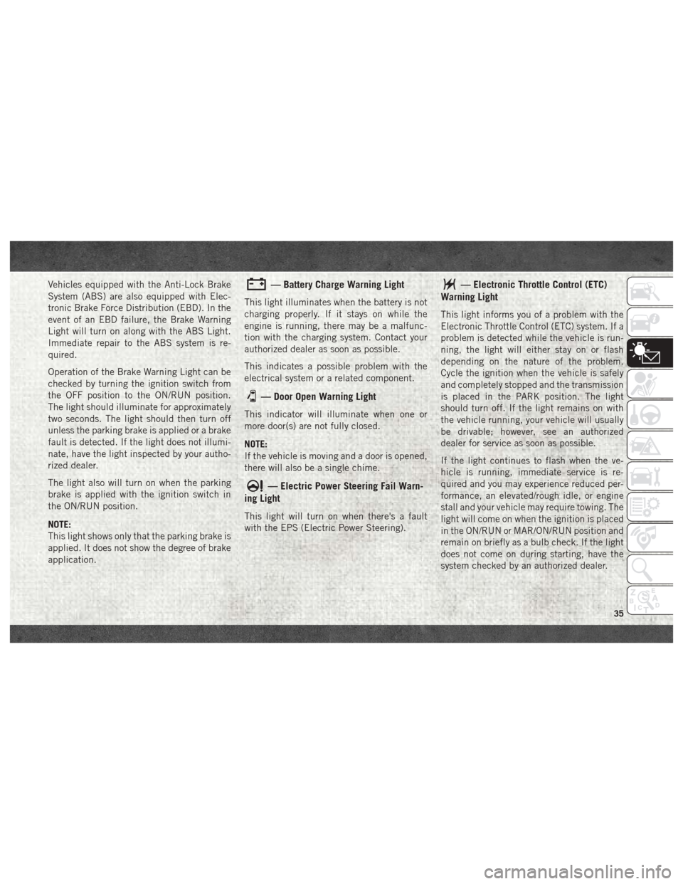
application.— Battery Charge Warning Light
This light illuminates when the battery is not
charging properly. If it stays on while the
engine is running, there may be a malfunc-
tion with the charging system. Contact your
authorized dealer as soon as possible.
This indicates a possible problem with the
electrical system or a related component.
— Door Open Warning Light
This indicator will illuminate when one or
more door(s) are not fully closed.
NOTE:
If the vehicle is moving and a door is opened,
there will also be a single chime.
— Electric Power Steering Fail Warn-
ing Light
This light will turn on when there's a fault
with the EPS (Electric Power Steering).
— Electronic Throttle Control (ETC)
Warning Light
This light informs you of a problem with the
Electronic Throttle Control (ETC) system. If a
problem is detected while the vehicle is run-
ning, the light will either stay on or flash
depending on the nature of the problem.
Cycle the ignition when the vehicle is safely
and completely stopped and the transmission
is placed in the PARK position. The light
should turn off. If the light remains on with
the vehicle running, your vehicle will usually
be drivable; however, see an authorized
dealer for service as soon as possible.
If the light continues to flash when the ve-
hicle is running, immediate service is re-
quired and you may experience reduced per-
formance, an elevated/rough idle, or engine
stall and your vehicle may require towing. The
light will come on when the ignition is placed
in the ON/RUN or MAR/ON/RUN position and
remain on briefly as a bulb check. If the light
does not come on during starting, have the
system checked by an authorized dealer.
35
Page 57 of 204
WARNING!
• Failure to replace the seat belt assemblycould increase the risk of injury in colli-
sions.
• Do not use the Automatic Locking Mode
to restrain occupants who are wearing
the seat belt or children who are using
booster seats. The locked mode is only
used to install rear-facing or forward-
facing child restraints that have a har-
ness for restraining the child.
Supplemental Restraint Systems
(SRS)
Some of the safety features described in this
section may be standard equipment on some
models, or may be optional equipment on
others. If you are not sure, ask your autho-
rized dealer.
The air bag system must be ready to protect
you in a collision. The Occupant Restraint
Controller (ORC) monitors the internal cir-
cuits and interconnecting wiring associated with the electrical Air Bag System Compo-
nents. Your vehicle may be equipped with the
following Air Bag System Components:
Air Bag System Components
• Occupant Restraint Controller (ORC)
• Air Bag Warning Light
• Steering Wheel and Column
• Instrument Panel
• Driver and Front Passenger Air Bags
• Seat Belt Buckle Switch
• Supplemental Side Air Bags
• Front and Side Impact Sensors
• Seat Belt Pretensioners
Air Bag Warning Light
The ORC monitors the readiness of the
electronic parts of the air bag system when-
ever the ignition switch is in the AVV/START
or MAR/ACC/ON/RUN position. If the ignition
switch is in the STOP/OFF/LOCK position the
air bag system is not on and the air bags will
not inflate. The ORC contains a backup power supply
system that may deploy the air bag system
even if the battery loses power or it becomes
disconnected prior to deployment.
The ORC turns on the Air Bag Warning Light
in the instrument panel for approximately
four to eight seconds for a self-check when
the ignition switch is in the MAR/ACC/ON/
RUN position. After the self-check, the Air
Bag Warning Light will turn off. If the ORC
detects a malfunction in any part of the
system, it turns on the Air Bag Warning Light,
either momentarily or continuously. A single
chime will sound to alert you if the light
comes on again after initial startup.
The ORC also includes diagnostics that will
illuminate the instrument panel Air Bag
Warning Light if a malfunction is detected
that could affect the air bag system. The
diagnostics also record the nature of the
malfunction. While the air bag system is
designed to be maintenance free, if any of the
following occurs, have an authorized dealer
service the air bag system immediately.
55
Page 64 of 204
Fuel Cut Off Switch
Your vehicle is equipped with a Fuel Cut Off
safety switch. In the event of an accident, if
the communication network remains intact,
and the power remains intact, depending on
the nature of the event, the Fuel Cut Off
Switch may perform the following functions:
• Cut off fuel to the engine and turn off theengine.
• Flash hazard lights as long as the battery has power or until the hazard light button is
pressed. The hazard lights can be deacti-
vated by pressing the hazard light button.
• Turn on the interior lights, which remain on as long as the battery has power.
• Unlock the power door locks. NOTE:
After an accident, remember to cycle the
ignition to the STOP (OFF/LOCK) position
and remove the key from the ignition switch
to avoid draining the battery. Carefully check
the vehicle for fuel leaks in the engine com-
partment and on the ground near the engine
compartment and fuel tank before resetting
the system and starting the engine. If there
are no fuel leaks or damage to the vehicle
electrical devices (e.g. headlights) after an
accident, reset the Fuel Cut Off Switch by
following the procedure described below.
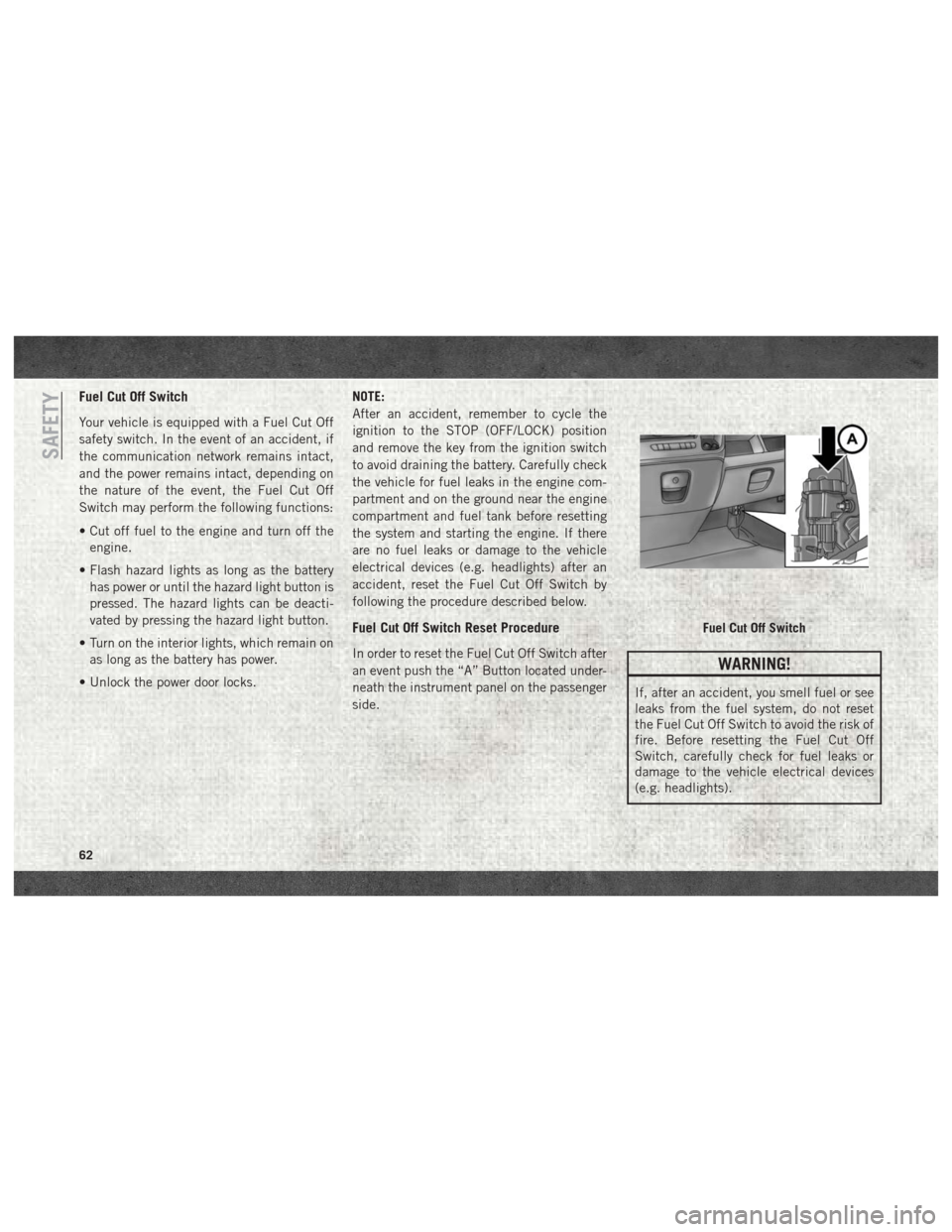
Fuel Cut Off Switch Reset Procedure
In order to reset the Fuel Cut Off Switch after
an event push the “A” Button located under-
neath the instrument panel on the passenger
side.WARNING!
If, after an accident, you smell fuel or see
leaks from the fuel system, do not reset
the Fuel Cut Off Switch to avoid the risk of
fire. Before resetting the Fuel Cut Off
Switch, carefully check for fuel leaks or
damage to the vehicle electrical devices
(e.g. headlights).
Fuel Cut Off Switch
SAFETY
62
Page 90 of 204

Towing The Vehicle
NOTE:
• The information in this section is for Auto-mated Manual Transmission (Diesel En-
gine) models ONLY. DO NOT flat tow any
model with a gasoline engine. Gasoline
engine models MUST be towed with front
wheels OFF the ground. See "Recreational
Towing" for additional information.
• For vehicles equipped with Electric Park Brake, you must ensure that the Auto Park
Brake feature is disabled before being
towed, to avoid inadvertent Electric Park
Brake engagement. The Auto Park Brake
feature can be temporarily disabled by
holding the park brake switch in the off
position while turning the ignition key from
ON/RUN to “OFF”.
• Vehicles with a discharged battery or total electrical failure when the Electric Park
Brake (EPB) is engaged, will need a wheel
dolly or jack to raise the rear wheels off the
ground when moving the vehicle onto a
flatbed. • The manufacturer recommends towing your
vehicle with all four wheels OFFthe ground
using a flatbed.
• Automated Manual transmission vehicles can also be flat towed (all four wheels on
the ground) with the transmission in NEU-
TRAL. Ensure the transmission is in NEU-
TRAL (N) (by checking that the vehicle
moves when pushed) and tow in the same
way as a normal vehicle with a manual
transmission.
If it is not possible to shift the transmission to
NEUTRAL (N), do not flat tow the vehicle and
contact your authorized dealer.
If you must use the accessories (wipers, de-
frosters, etc.) while being towed, the ignition
must be in the ON/RUN mode. NOTE:
For vehicles equipped with Electric Park
Brake the SafeHold feature will engage the
Electric Park Brake whenever the driver's
door is opened (if the ignition is ON and the
brake pedal is released). If you are towing
this vehicle with the ignition in the ON/RUN
position, you must manually disable the Elec-
tric Park Brake each time the driver's door is
opened, by pressing the brake pedal and then
releasing the EPB.
CAUTION!
• DO NOT flat tow any disabled vehicle if
condition is related to the clutch,
transmission or driveline. Additional
damage to the drivetrain could result.
• Towing this vehicle in violation of the
above requirements can cause severe
engine, transmission, or drivetrain
damage. Damage from improper tow-
ing is not covered under the New Ve-
hicle Limited Warranty.
• Ensure that the electric park brake (if
equipped) is released, and remains re-
leased, while being towed.STARTING AND OPERATING
88
Page 101 of 204

IN CASE OF EMERGENCY
BULB REPLACEMENT...........100
Replacement Bulbs............100
FUSES.................... .102
Underhood Fuses..............103
Interior Fuses ................106
Right Central Pillar Fuses .........107
JACKING AND TIRE CHANGING .....108
Jack Location................108
Spare Tire Removal .............109
Preparations For Jacking .........111
Jacking Instructions .............112
Wheel Covers ................115
JUMP STARTING ..............115
Preparations For Jump Start ........116
Jump Starting Procedure .........117
Battery Location ..............118
IF YOUR ENGINE OVERHEATS ......118
GEAR SELECTOR OVERRIDE
(GASOLINE ENGINE ONLY) ........119
FREEING A STUCK VEHICLE .......119
TOWING A DISABLED VEHICLE .....121
Automatic Transmission..........122
ENHANCED ACCIDENT RESPONSE
SYSTEM (EARS)...............122
EVENT DATA RECORDER (EDR) ......122
IN CASE OF EMERGENCY
99
Page 109 of 204

Right Central Pillar Fuses
The right central pillar fuse panel is located
on the interior side at the base of the passen-
ger side B pillar.
CavityMini Fuse Description
F81 7.5 Amp Brown Seat Heater
F83 20 Amp YellowRear Left Windows Heater
F84 20 Amp YellowRear Right Windows Heater
F86 20 Amp YellowAuxiliary Switch (From Battery) — If Equipped
F87 20 Amp YellowAuxiliary Switch (From Ignition) — If Equipped
107
Page 117 of 204
CAUTION!
Be sure to mount the spare tire with the
valve stem facing outward. The vehicle
could be damaged if the spare tire is
mounted incorrectly.NOTE:
Do not install the wheel cover on the spare
tire.
7. Lower the vehicle by turning the jack screw to the left.
8. Refer to “Wheel And Tire Torque Specifi- cations” in “Technical Specifications” for
proper wheel lug bolt torque.
9. Lower the jack to its fully-closed position.
10. Stow the damaged wheel/spare tire with the cable and wheel spacer before driv-
ing the vehicle.
11. Install the winch extension and rotate the
wrench handle clockwise until the winch
mechanism operator hears “3 clicks” from
the device to indicate the wheel is properly
stowed under the vehicle. 12. Stow the jack, jack handle and winch
handle tools back in the storage
compartment.
WARNING!
A loose tire or jack thrown forward in a
collision or hard stop could endanger the
occupants of the vehicle. Always stow the
jack parts and the spare tire in the places
provided. Have the deflated (flat) tire re-
paired or replaced immediately.
13. Check the spare tire pressure as soon as possible. Correct the tire pressure, as
required.
For vehicles with aluminum wheels:
The center cap must be pushed out from the
rear to install the retainer and stow the tire.
Wheel Covers
CAUTION!
Use a back-and-forth motion to remove the
hub cap. Do not use a twisting motion when
removing the hub cap, damage to the hub
cap finish may occur.
The wheel covers on the vehicle are held in
place by the wheel lug bolts and can be
removed after the wheel lug bolts are taken
off.
JUMP STARTING
If your vehicle has a discharged battery, it can
be jump started using a set of jumper cables
and a battery in another vehicle or by using a
portable battery booster pack. Jump starting
can be dangerous if done improperly, so
please follow the procedures in this section
carefully.
NOTE:
When using a portable battery booster pack,
follow the manufacturer’s operating instruc-
tions and precautions.
115
Page 118 of 204
WARNING!
Do not attempt jump starting if the battery
is frozen. It could rupture or explode and
cause personal injury.
CAUTION!
Do not use a portable battery booster pack
or any other booster source with a system
voltage greater than 12 Volts or damage to
the battery, starter motor, alternator or
electrical system may occur.
Preparations For Jump Start
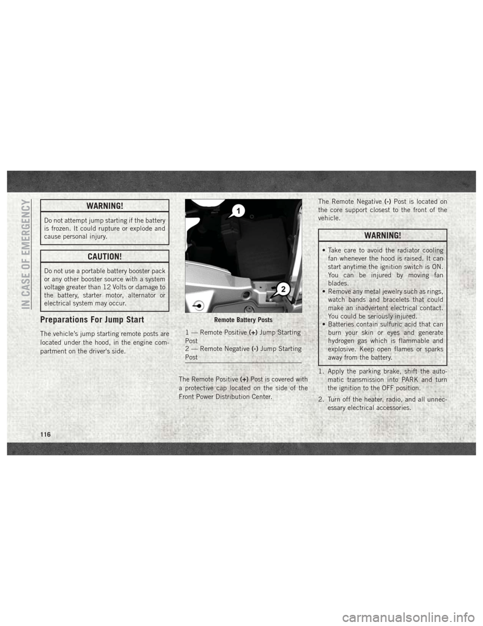
The vehicle’s jump starting remote posts are
located under the hood, in the engine com-
partment on the driver's side.The Remote Positive(+)Post is covered with
a protective cap located on the side of the
Front Power Distribution Center. The Remote Negative
(-)Post is located on
the core support closest to the front of the
vehicle.
WARNING!
• Take care to avoid the radiator cooling fan whenever the hood is raised. It can
start anytime the ignition switch is ON.
You can be injured by moving fan
blades.
• Remove any metal jewelry such as rings,
watch bands and bracelets that could
make an inadvertent electrical contact.
You could be seriously injured.
• Batteries contain sulfuric acid that can
burn your skin or eyes and generate
hydrogen gas which is flammable and
explosive. Keep open flames or sparks
away from the battery.
1. Apply the parking brake, shift the auto- matic transmission into PARK and turn
the ignition to the OFF position.
2. Turn off the heater, radio, and all unnec- essary electrical accessories.
Remote Battery Posts
1 — Remote Positive (+)Jump Starting
Post
2 — Remote Negative (-)Jump Starting
Post
IN CASE OF EMERGENCY
116