light Ram ProMaster 2018 User Guide
[x] Cancel search | Manufacturer: RAM, Model Year: 2018, Model line: ProMaster, Model: Ram ProMaster 2018Pages: 204, PDF Size: 4 MB
Page 13 of 204

GETTING TO KNOW YOUR VEHICLE
KEYS......................12
KeyFob.....................12
SEATS .....................13
Heated Seats — If Equipped ........13
Adjustable Armrests — If Equipped ....14
HEAD RESTRAINTS..............14
Front Head Restraint Adjustment .....15
Front Head Restraint Removal .......15
STEERING WHEEL..............16
Telescoping Steering Column .......16
EXTERIOR LIGHTS..............16
Multifunction Lever ..............16
Headlights ...................17
High Beam/Low Beam Select Switch . . .17
Parking Lights .................17
Turn Signals ..................17
Lane Change Assist .............17
INTERIOR LIGHTS...............17
WIPERS AND WASHERS ..........17
Front Wiper Operation............17
CLIMATE CONTROLS.............19
Manual Climate Control Overview .....19
Climate Control Functions ..........22
Operating Tips .................23
HOOD......................24
Opening .....................24
Closing .....................24
INTERNAL EQUIPMENT ...........25
Power Outlets.................25
GETTING TO KNOW YOUR VEHICLE
11
Page 14 of 204
KEYS
Key Fob
Your vehicle uses a key start ignition system.
The ignition system consists of a key fob with
a Remote Keyless Entry (RKE) and an igni-
tion switch.
The key fob contains an integrated mechani-
cal key. To use the mechanical key, simply
push the mechanical key release button.
The vehicle is supplied with a code card
containing key code numbers to order dupli-
cate keys, and the authorized dealer that sold
you your new vehicle has the key code num-
bers for your vehicle locks. These numbers
can be used to order duplicate keys.Remote Keyless Entry (RKE)
This system allows you to lock or unlock the
doors from distances up to approximately
66 ft (20 m) using a hand-held key fob. The
key fob does not need to be pointed at the
vehicle to activate the system. NOTE:
The key fob may not be able to be detected by
the vehicle if it is located next to a mobile
phone, laptop or other electronic device;
these devices may block the key fob’s wire-
less signal.
To Unlock The Doors
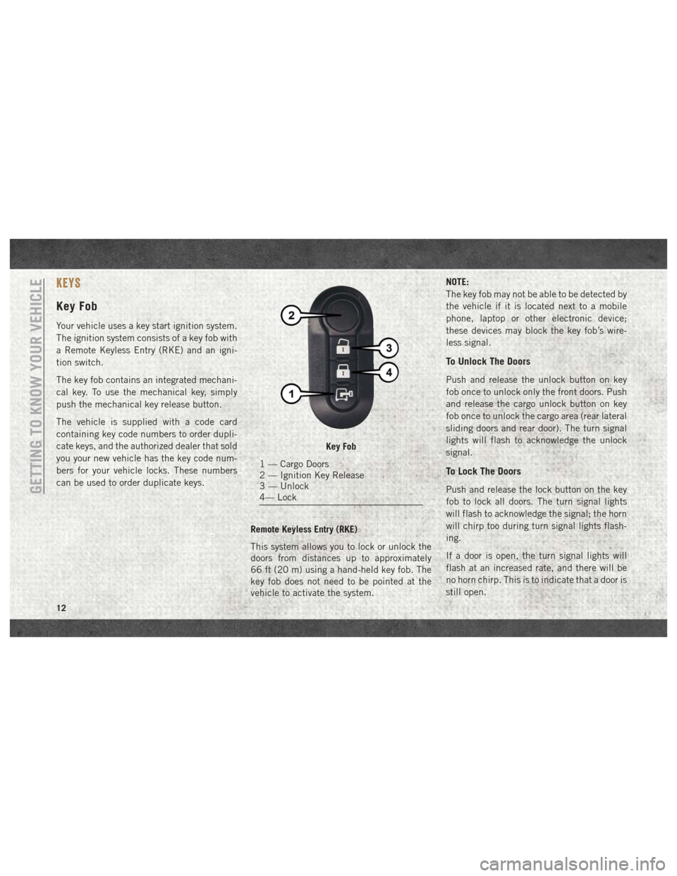
Push and release the unlock button on key
fob once to unlock only the front doors. Push
and release the cargo unlock button on key
fob once to unlock the cargo area (rear lateral
sliding doors and rear door). The turn signal
lights will flash to acknowledge the unlock
signal.
To Lock The Doors
Push and release the lock button on the key
fob to lock all doors. The turn signal lights
will flash to acknowledge the signal; the horn
will chirp too during turn signal lights flash-
ing.
If a door is open, the turn signal lights will
flash at an increased rate, and there will be
no horn chirp. This is to indicate that a door is
still open.
Key Fob
1 — Cargo Doors
2 — Ignition Key Release
3 — Unlock
4— Lock
GETTING TO KNOW YOUR VEHICLE
12
Page 18 of 204
STEERING WHEEL
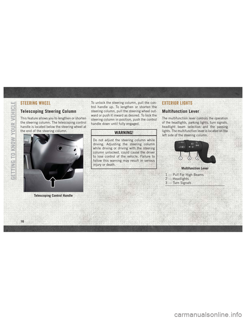
Telescoping Steering Column
This feature allows you to lengthen or shorten
the steering column. The telescoping control
handle is located below the steering wheel at
the end of the steering column.To unlock the steering column, pull the con-
trol handle up. To lengthen or shorten the
steering column, pull the steering wheel out-
ward or push it inward as desired. To lock the
steering column in position, push the control
handle down until fully engaged.
WARNING!
Do not adjust the steering column while
driving. Adjusting the steering column
while driving or driving with the steering
column unlocked, could cause the driver
to lose control of the vehicle. Failure to
follow this warning may result in serious
injury or death.
EXTERIOR LIGHTS
Multifunction Lever
The multifunction lever controls the operation
of the headlights, parking lights, turn signals,
headlight beam selection and the passing
lights. The multifunction lever is located on the
left side of the steering column.
Telescoping Control Handle
Multifunction Lever
1 — Pull For High Beams
2 — Headlights
3 — Turn Signals
GETTING TO KNOW YOUR VEHICLE
16
Page 19 of 204
Headlights
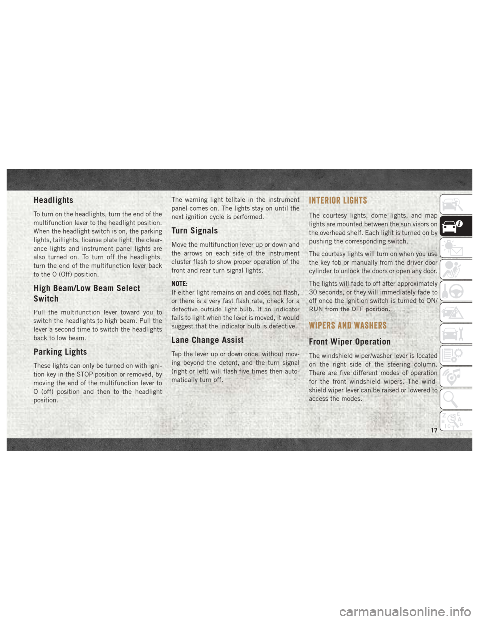
To turn on the headlights, turn the end of the
multifunction lever to the headlight position.
When the headlight switch is on, the parking
lights, taillights, license plate light, the clear-
ance lights and instrument panel lights are
also turned on. To turn off the headlights,
turn the end of the multifunction lever back
to the O (Off) position.
High Beam/Low Beam Select
Switch
Pull the multifunction lever toward you to
switch the headlights to high beam. Pull the
lever a second time to switch the headlights
back to low beam.
Parking Lights
These lights can only be turned on with igni-
tion key in the STOP position or removed, by
moving the end of the multifunction lever to
O (off) position and then to the headlight
position.The warning light telltale in the instrument
panel comes on. The lights stay on until the
next ignition cycle is performed.
Turn Signals
Move the multifunction lever up or down and
the arrows on each side of the instrument
cluster flash to show proper operation of the
front and rear turn signal lights.
NOTE:
If either light remains on and does not flash,
or there is a very fast flash rate, check for a
defective outside light bulb. If an indicator
fails to light when the lever is moved, it would
suggest that the indicator bulb is defective.
Lane Change Assist
Tap the lever up or down once, without mov-
ing beyond the detent, and the turn signal
(right or left) will flash five times then auto-
matically turn off.
INTERIOR LIGHTS
The courtesy lights, dome lights, and map
lights are mounted between the sun visors on
the overhead shelf. Each light is turned on by
pushing the corresponding switch.
The courtesy lights will turn on when you use
the key fob or manually from the driver door
cylinder to unlock the doors or open any door.
The lights will fade to off after approximately
30 seconds, or they will immediately fade to
off once the ignition switch is turned to ON/
RUN from the OFF position.
WIPERS AND WASHERS
Front Wiper Operation
The windshield wiper/washer lever is located
on the right side of the steering column.
There are five different modes of operation
for the front windshield wipers. The wind-
shield wiper lever can be raised or lowered to
access the modes.
17
Page 23 of 204
IconDescription
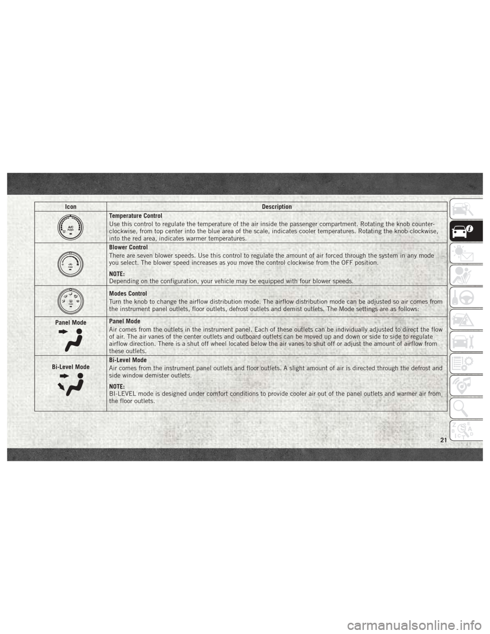
Temperature Control
Use this control to regulate the temperature of the air inside the passenger compartment. Rotating the knob counter-
clockwise, from top center into the blue area of the scale, indicates cooler temperatures. Rotating the knob clockwise,
into the red area, indicates warmer temperatures.
Blower Control
There are seven blower speeds. Use this control to regulate the amount of air forced through the system in any mode
you select. The blower speed increases as you move the control clockwise from the OFF position.
NOTE:
Depending on the configuration, your vehicle may be equipped with four blower speeds.
Modes Control
Turn the knob to change the airflow distribution mode. The airflow distribution mode can be adjusted so air comes from
the instrument panel outlets, floor outlets, defrost outlets and demist outlets. The Mode settings are as follows:
Panel Mode
Panel Mode
Air comes from the outlets in the instrument panel. Each of these outlets can be individually adjusted to direct the flow
of air. The air vanes of the center outlets and outboard outlets can be moved up and down or side to side to regulate
airflow direction. There is a shut off wheel located below the air vanes to shut off or adjust the amount of airflow from
these outlets.
Bi-Level Mode
Bi-Level Mode
Air comes from the instrument panel outlets and floor outlets. A slight amount of air is directed through the defrost and
side window demister outlets.
NOTE:
BI-LEVEL mode is designed under comfort conditions to provide cooler air out of the panel outlets and warmer air from
the floor outlets.
21
Page 24 of 204
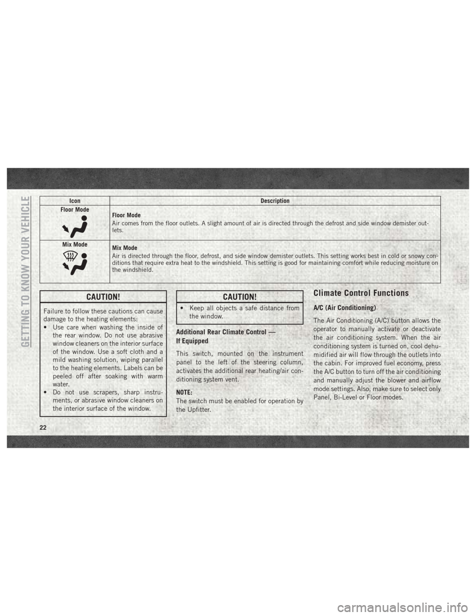
IconDescription
Floor Mode
Floor Mode
Air comes from the floor outlets. A slight amount of air is directed through the defrost and side window demister out-
lets.
Mix Mode
Mix Mode
Air is directed through the floor, defrost, and side window demister outlets. This setting works best in cold or snowy con-
ditions that require extra heat to the windshield. This setting is good for maintaining comfort while reducing moisture on
the windshield.
CAUTION!
Failure to follow these cautions can cause
damage to the heating elements:
• Use care when washing the inside of the rear window. Do not use abrasive
window cleaners on the interior surface
of the window. Use a soft cloth and a
mild washing solution, wiping parallel
to the heating elements. Labels can be
peeled off after soaking with warm
water.
• Do not use scrapers, sharp instru-
ments, or abrasive window cleaners on
the interior surface of the window.
CAUTION!
• Keep all objects a safe distance fromthe window.
Additional Rear Climate Control —
If Equipped
This switch, mounted on the instrument
panel to the left of the steering column,
activates the additional rear heating/air con-
ditioning system vent.
NOTE:
The switch must be enabled for operation by
the Upfitter.
Climate Control Functions
A/C (Air Conditioning)
The Air Conditioning (A/C) button allows the
operator to manually activate or deactivate
the air conditioning system. When the air
conditioning system is turned on, cool dehu-
midified air will flow through the outlets into
the cabin. For improved fuel economy, press
the A/C button to turn off the air conditioning
and manually adjust the blower and airflow
mode settings. Also, make sure to select only
Panel, Bi-Level or Floor modes.
GETTING TO KNOW YOUR VEHICLE
22
Page 27 of 204
CAUTION!
edge of the hood to ensure that both
latches engage. Never drive your vehicle
unless the hood is fully closed, with both
latches engaged.
INTERNAL EQUIPMENT
Power Outlets
Passenger Compartment Power Outlet
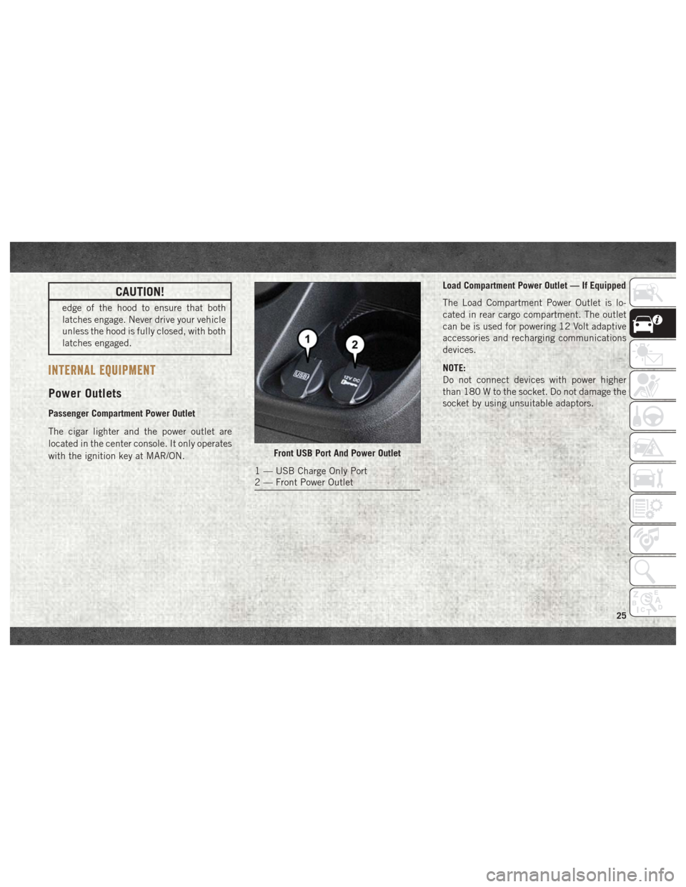
The cigar lighter and the power outlet are
located in the center console. It only operates
with the ignition key at MAR/ON.Load Compartment Power Outlet — If Equipped
The Load Compartment Power Outlet is lo-
cated in rear cargo compartment. The outlet
can be is used for powering 12 Volt adaptive
accessories and recharging communications
devices.
NOTE:
Do not connect devices with power higher
than 180 W to the socket. Do not damage the
socket by using unsuitable adaptors.
Front USB Port And Power Outlet
1 — USB Charge Only Port
2 — Front Power Outlet
25
Page 29 of 204
WARNING!
To avoid serious injury or death:
• Only devices designed for use in thistype of outlet should be inserted into any
12 Volt outlet.
• Do not touch with wet hands.
• Close the lid when not in use and while
driving the vehicle.
• If this outlet is mishandled, it may cause
an electric shock and failure.
CAUTION!
• Many accessories that can be plugged indraw power from the vehicle's battery,
even when not in use (i.e., cellular
phones, etc.). Eventually, if plugged in
long enough, the vehicle's battery will
discharge sufficiently to degrade battery
life and/or prevent the engine from start-
ing.
• Accessories that draw higher power (i.e.,
coolers, vacuum cleaners, lights, etc.)
will degrade the battery even more
CAUTION!
quickly. Only use these intermittently
and with greater caution.
• After the use of high power draw acces-
sories, or long periods of the vehicle not
being started (with accessories still
plugged in), the vehicle must be driven a
sufficient length of time to allow the
generator to recharge the vehicle's bat-
tery.
27
Page 31 of 204
GETTING TO KNOW YOUR INSTRUMENT PANEL
INSTRUMENT CLUSTER DISPLAY.....30
Location And Controls............30
Diesel Messages — If Equipped ......31
WARNING LIGHTS AND MESSAGES ....34
Red Warning Lights..............34 Yellow Warning Lights
............37
Yellow Indicator Lights ............40
Green Indicator Lights ............41
Blue Indicator Lights .............41
ONBOARD DIAGNOSTIC SYSTEM —
OBDII .....................42
Onboard Diagnostic System (OBD II)
Cybersecurity.................42
GETTING TO KNOW YOUR INSTRUMENT PANEL
29
Page 33 of 204
•Up Arrow Button
Push and release the uparrow button to
scroll upward through the main menu and
submenus or adjust the illumination on the
instrument panel when the headlights are
on.
• Down Arrow Button
Push and release the downarrow button to
scroll downward through the main menu
and submenus or adjust the illumination on
the instrument panel when the headlights
are on.
Diesel Messages — If Equipped
Diesel Messages
Diesel Particulate Filter (DPF) Messages
• “DPF cleaning: safely keep the vehicle moving” message in the Display + Engine
emission filter lamp lighted solid indicates
that the exhaust particulate filter loading is
above the specified range and a regenera-
tion is required. • Safely Drive at Highway Speeds to Remedy
(the procedure lasts roughly 15 minutes at
speed of about 40 mph (60 km/h) and with
engine speed above approximately
2000 rpm).
• When the exaust filter is overloaded, the MIL lamp will turn on and the “Service
engine” message will be in the Instrument
Cluster Display, ETC lamp blinks and the
PCM limits the engine power to limit the
likelihood of permanent damage to the
after-treatment system. To correct this con-
dition, it will be necessary to have your
vehicle serviced by an authorized dealer.
CAUTION!
See your authorized dealer, as damage to
the exhaust system could occur soon with
continued operation. Diesel Exhaust Fluid (DEF) Messages
•First low level warning will be given at
around 500 miles, which is determined by
current consumption rate. DEF Low level
lamp icon and display message for refill
will be displayed at dashboard. DEF Low
level Lamp will stay on until a DEF refill is
detected (minimum 1 gallon).
• To correct, this condition it will be neces- sary to fully refill the DEF tank.
• If refill is not performed, a second low level warning will be given about 200 miles are
left to empty the DEF Tank.
• Display message of speed limitation with DEF Low Level lamp will be there on dash-
board.
• The driver will be informed about the speed restriction also when about 150 and
125 miles are left to empty the DEF Tank.
• When 100 miles are left to empty, the DEF Tank, a continuous message display with
chimes will be there on dashboard.
31