fuel pressure Ram ProMaster 2018 User Guide
[x] Cancel search | Manufacturer: RAM, Model Year: 2018, Model line: ProMaster, Model: Ram ProMaster 2018Pages: 204, PDF Size: 4 MB
Page 39 of 204
Yellow Warning Lights
— Vehicle Security Warning Light
This telltale will illuminate when the vehicle
security alarm system has detected an at-
tempt was made to break into the vehicle.
— Tire Pressure Monitoring System
(TPMS) Warning Light
The warning light switches on and a message
is displayed to indicate that the tire pressure
is lower than the recommended value and/or
that slow pressure loss is occurring. In these
cases, optimal tire duration and fuel con-
sumption may not be guaranteed.
Should one or more tires be in the condition
mentioned above, the display will show the
indications corresponding to each tire in
sequence.
CAUTION!
Do not continue driving with one or more
flat tires as handling may be compro-
mised. Stop the vehicle, avoiding sharp
braking and steering. If a tire puncture
CAUTION!
occurs, repair immediately using the dedi-
cated tire repair kit and contact your au-
thorized dealer as soon as possible.
Each tire, including the spare (if provided),
should be checked monthly when cold and
inflated to the inflation pressure recom-
mended by the vehicle manufacturer on the
vehicle placard or tire inflation pressure la-
bel. (If your vehicle has tires of a different
size than the size indicated on the vehicle
placard or tire inflation pressure label, you
should determine the proper tire inflation
pressure for those tires.)
As an added safety feature, your vehicle has
been equipped with a tire pressure monitor-
ing system (TPMS) that illuminates a low tire
pressure telltale when one or more of your
tires is significantly under-inflated. Accord-
ingly, when the low tire pressure telltale illu-
minates, you should stop and check your tires
as soon as possible, and inflate them to the
proper pressure. Driving on a significantly
under-inflated tire causes the tire to overheat and can lead to tire failure. Under-inflation
also reduces fuel efficiency and tire tread
life, and may affect the vehicle’s handling
and stopping ability.
Please note that the TPMS is not a substitute
for proper tire maintenance, and it is the
driver’s responsibility to maintain correct tire
pressure, even if under-inflation has not
reached the level to trigger illumination of the
TPMS low tire pressure telltale.
Your vehicle has also been equipped with a
TPMS malfunction indicator to indicate when
the system is not operating properly. The
TPMS malfunction indicator is combined
with the low tire pressure telltale. When the
system detects a malfunction, the telltale will
flash for approximately one minute and then
remain continuously illuminated. This se-
quence will continue upon subsequent ve-
hicle start-ups as long as the malfunction
exists. When the malfunction indicator is
illuminated, the system may not be able to
detect or signal low tire pressure as intended.
TPMS malfunctions may occur for a variety of
reasons, including the installation of replace-
ment or alternate tires or wheels on the ve-
37
Page 41 of 204
Certain conditions, such as a loose or missing
gas cap, poor quality fuel, etc., may illumi-
nate the light after engine start. The vehicle
should be serviced if the light stays on
through several typical driving styles. In most
situations, the vehicle will drive normally and
will not require towing.
When the engine is running, the MIL may
flash to alert serious conditions that could
lead to immediate loss of power or severe
catalytic converter damage. The vehicle
should be serviced as soon as possible if this
occurs.
WARNING!
A malfunctioning catalytic converter, as
referenced above, can reach higher tem-
peratures than in normal operating condi-
tions. This can cause a fire if you drive
slowly or park over flammable substances
such as dry plants, wood, cardboard, etc.
This could result in death or serious injury
to the driver, occupants or others.
CAUTION!
Prolonged driving with the Malfunction
Indicator Light (MIL) on could cause dam-
age to the vehicle control system. It also
could affect fuel economy and driveability.
If the MIL is flashing, severe catalytic
converter damage and power loss will soon
occur. Immediate service is required.
— Anti-Lock Brake (ABS) Warning
Light
This light monitors the Anti-Lock Brake Sys-
tem (ABS). The light will turn on when the
ignition is placed in the ON/RUN or MAR/ON/
RUN position and may stay on for as long as
four seconds.
If the ABS light remains on or turns on while
driving, then the Anti-Lock portion of the
brake system is not functioning and service is
required. However, the conventional brake
system will continue to operate normally if
the brake warning light is not on. If the ABS light is on, the brake system
should be serviced as soon as possible to
restore the benefits of Anti-Lock Brakes. If
the ABS light does not turn on when the
ignition is placed in the ON/RUN or MAR/ON/
RUN position, have the light inspected by an
authorized dealer.
— Generic Warning Light
The Generic Warning Light will illuminate if
any of the following conditions occur: Engine
Oil Pressure Sensor Failure, External Light
Failure, Fuel Cut-Off intervention or fail,
Parking Sensor Failure, DST System Failure.
The telltale will remain on fixed in case of
swivel seat failure and on blinking in case of
Air Bag Warning Light Failure. Contact an
authorized dealer immediately for service.
39
Page 47 of 204
CAUTION!
• The TPMS has been optimized for theoriginal equipment tires and wheels.
TPMS pressures and warning have been
established for the tire size equipped on
your vehicle. Undesirable system opera-
tion or sensor damage may result when
using replacement equipment that is not
of the same size, type, and/or style.
Aftermarket wheels can cause sensor
damage.
• Using aftermarket tire sealants may
cause the Tire Pressure Monitoring Sys-
tem (TPMS) sensor to become inoper-
able. After using an aftermarket tire
sealant it is recommended that you take
your vehicle to an authorized dealership
to have your sensor function checked.
• After inspecting or adjusting the tire
pressure always reinstall the valve stem
cap. This will prevent moisture and dirt
from entering the valve stem, which
could damage the TPMS sensor. NOTE:
• The TPMS is not intended to replace nor-
mal tire care and maintenance or to provide
warning of a tire failure or condition.
• The TPMS should not be used as a tire pressure gauge while adjusting your tire
pressure.
• Driving on a significantly under-inflated tire causes the tire to overheat and can lead to
tire failure. Under-inflation also reduces
fuel efficiency and tire tread life, and may
affect the vehicle’s handling and stopping
ability.
• The TPMS is not a substitute for proper tire maintenance, and it is the driver’s respon-
sibility to maintain correct tire pressure
using an accurate tire pressure gauge, even
if under-inflation has not reached the level
to trigger illumination of the TPM Telltale
Light.
• Seasonal temperature changes will affect tire pressure, and the TPMS will monitor
the actual tire pressure in the tire.
Base System
This is the TPMS warning indicator
located in the instrument cluster.
The TPMS uses wireless technology
with wheel rim mounted electronic sensors to
monitor tire pressure levels. Sensors,
mounted to each wheel as part of the valve
stem, transmit tire pressure readings to the
Receiver Module.
NOTE:
It is particularly important for you to check
the tire pressure in all of the tires on your
vehicle regularly and to maintain the proper
pressure.
The TPMS consists of the following compo-
nents:
• Receiver Module.
• Four Tire Pressure Monitoring Sensors.
• Tire Pressure Monitoring Telltale Light.
45
Page 74 of 204
Periodic Safety Checks You
Should Make Outside The Vehicle
Tires
Examine tires for excessive tread wear and
uneven wear patterns. Check for stones,
nails, glass, or other objects lodged in the
tread or sidewall. Inspect the tread for cuts
and cracks. Inspect sidewalls for cuts,
cracks, and bulges. Check the wheel bolts for
tightness. Check the tires (including spare)
for proper cold inflation pressure.
Lights
Have someone observe the operation of brake
lights and exterior lights while you work the
controls. Check turn signal and high beam
indicator lights on the instrument panel.
Door Latches
Check for proper closing, latching, and lock-
ing.
Fluid Leaks
Check area under the vehicle after overnight
parking for fuel, coolant, oil, or other fluid
leaks. Also, if gasoline fumes are detected or
if fuel, or brake fluid leaks are suspected. The
cause should be located and corrected imme-
diately.
SAFETY
72
Page 77 of 204
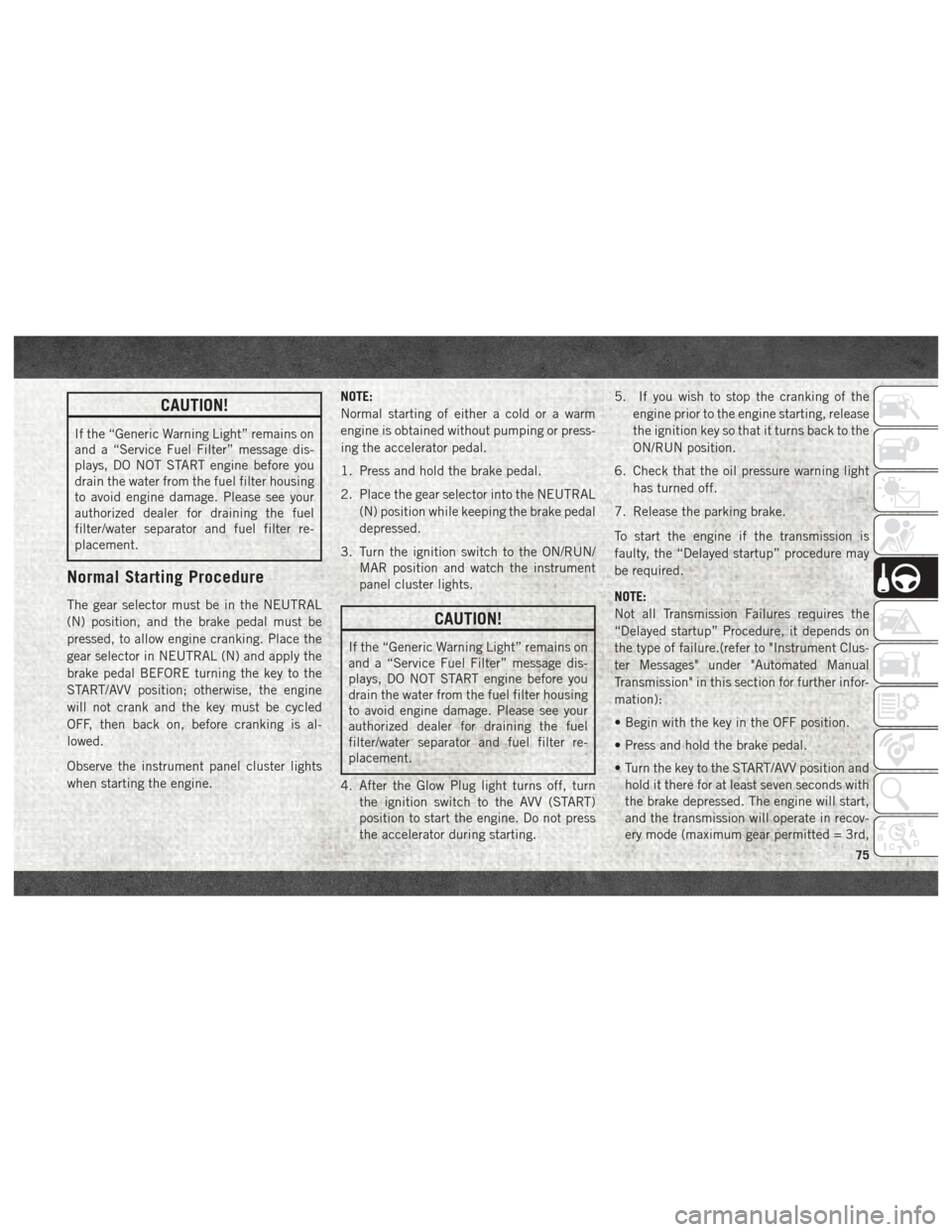
CAUTION!
If the “Generic Warning Light” remains on
and a “Service Fuel Filter” message dis-
plays, DO NOT START engine before you
drain the water from the fuel filter housing
to avoid engine damage. Please see your
authorized dealer for draining the fuel
filter/water separator and fuel filter re-
placement.
Normal Starting Procedure
The gear selector must be in the NEUTRAL
(N) position, and the brake pedal must be
pressed, to allow engine cranking. Place the
gear selector in NEUTRAL (N) and apply the
brake pedal BEFORE turning the key to the
START/AVV position; otherwise, the engine
will not crank and the key must be cycled
OFF, then back on, before cranking is al-
lowed.
Observe the instrument panel cluster lights
when starting the engine.NOTE:
Normal starting of either a cold or a warm
engine is obtained without pumping or press-
ing the accelerator pedal.
1. Press and hold the brake pedal.
2. Place the gear selector into the NEUTRAL
(N) position while keeping the brake pedal
depressed.
3. Turn the ignition switch to the ON/RUN/ MAR position and watch the instrument
panel cluster lights.CAUTION!
If the “Generic Warning Light” remains on
and a “Service Fuel Filter” message dis-
plays, DO NOT START engine before you
drain the water from the fuel filter housing
to avoid engine damage. Please see your
authorized dealer for draining the fuel
filter/water separator and fuel filter re-
placement.
4. After the Glow Plug light turns off, turn the ignition switch to the AVV (START)
position to start the engine. Do not press
the accelerator during starting. 5. If you wish to stop the cranking of the
engine prior to the engine starting, release
the ignition key so that it turns back to the
ON/RUN position.
6. Check that the oil pressure warning light has turned off.
7. Release the parking brake.
To start the engine if the transmission is
faulty, the “Delayed startup” procedure may
be required.
NOTE:
Not all Transmission Failures requires the
“Delayed startup” Procedure, it depends on
the type of failure.(refer to "Instrument Clus-
ter Messages" under "Automated Manual
Transmission" in this section for further infor-
mation):
• Begin with the key in the OFF position.
• Press and hold the brake pedal.
• Turn the key to the START/AVV position and hold it there for at least seven seconds with
the brake depressed. The engine will start,
and the transmission will operate in recov-
ery mode (maximum gear permitted = 3rd,
75
Page 78 of 204
automatic mode not available). If the en-
gine does not start, contact your authorized
dealer.
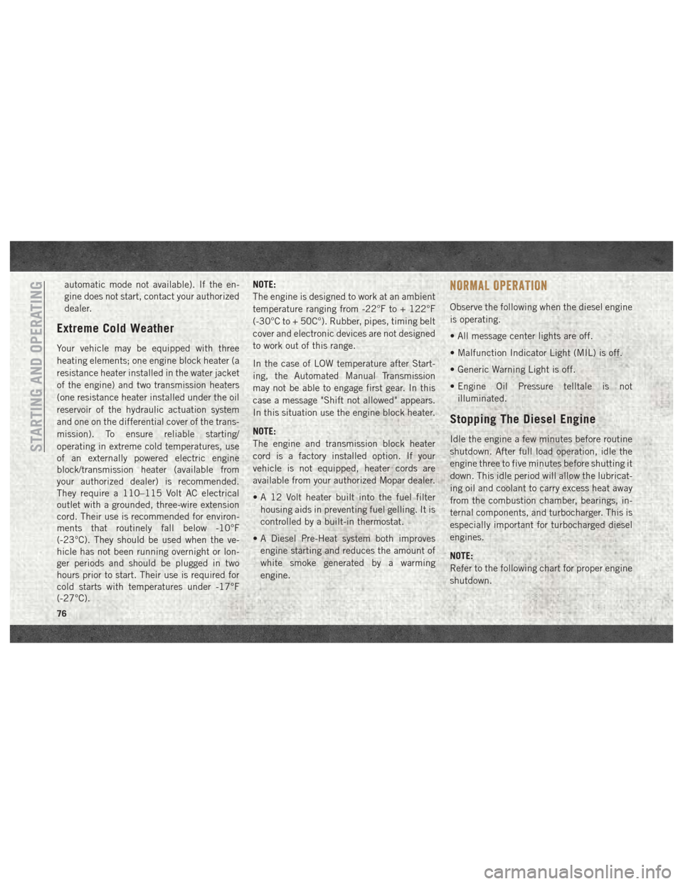
Extreme Cold Weather
Your vehicle may be equipped with three
heating elements; one engine block heater (a
resistance heater installed in the water jacket
of the engine) and two transmission heaters
(one resistance heater installed under the oil
reservoir of the hydraulic actuation system
and one on the differential cover of the trans-
mission). To ensure reliable starting/
operating in extreme cold temperatures, use
of an externally powered electric engine
block/transmission heater (available from
your authorized dealer) is recommended.
They require a 110–115 Volt AC electrical
outlet with a grounded, three-wire extension
cord. Their use is recommended for environ-
ments that routinely fall below -10°F
(-23°C). They should be used when the ve-
hicle has not been running overnight or lon-
ger periods and should be plugged in two
hours prior to start. Their use is required for
cold starts with temperatures under -17°F
(-27°C).NOTE:
The engine is designed to work at an ambient
temperature ranging from -22°F to + 122°F
(-30°C to + 50C°). Rubber, pipes, timing belt
cover and electronic devices are not designed
to work out of this range.
In the case of LOW temperature after Start-
ing, the Automated Manual Transmission
may not be able to engage first gear. In this
case a message "Shift not allowed" appears.
In this situation use the engine block heater.
NOTE:
The engine and transmission block heater
cord is a factory installed option. If your
vehicle is not equipped, heater cords are
available from your authorized Mopar dealer.
• A 12 Volt heater built into the fuel filter
housing aids in preventing fuel gelling. It is
controlled by a built-in thermostat.
• A Diesel Pre-Heat system both improves engine starting and reduces the amount of
white smoke generated by a warming
engine.
NORMAL OPERATION
Observe the following when the diesel engine
is operating.
• All message center lights are off.
• Malfunction Indicator Light (MIL) is off.
• Generic Warning Light is off.
• Engine Oil Pressure telltale is notilluminated.
Stopping The Diesel Engine
Idle the engine a few minutes before routine
shutdown. After full load operation, idle the
engine three to five minutes before shutting it
down. This idle period will allow the lubricat-
ing oil and coolant to carry excess heat away
from the combustion chamber, bearings, in-
ternal components, and turbocharger. This is
especially important for turbocharged diesel
engines.
NOTE:
Refer to the following chart for proper engine
shutdown.STARTING AND OPERATING
76
Page 93 of 204
WARNING!
ditions, and you could lose control and
have an accident. Do not use Speed Con-
trol in heavy traffic or on roads that are
winding, icy, snow-covered or slippery.
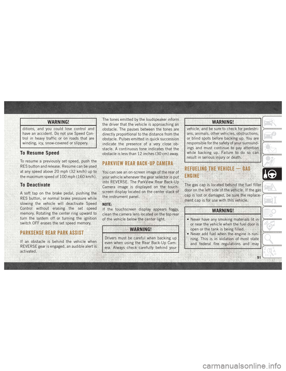
To Resume Speed
To resume a previously set speed, push the
RES button and release. Resume can be used
at any speed above 20 mph (32 km/h) up to
the maximum speed of 100 mph (160 km/h).
To Deactivate
A soft tap on the brake pedal, pushing the
RES button, or normal brake pressure while
slowing the vehicle will deactivate Speed
Control without erasing the set speed
memory. Rotating the center ring upward to
turn the system off or turning the ignition
switch OFF erases the set speed memory.
PARKSENSE REAR PARK ASSIST
If an obstacle is behind the vehicle when
REVERSE gear is engaged, an audible alert is
activated.The tones emitted by the loudspeaker inform
the driver that the vehicle is approaching an
obstacle. The pauses between the tones are
directly proportional to the distance from the
obstacle. Pulses emitted in quick succession
indicate the presence of a very close ob-
stacle. A continuous tone indicates that the
obstacle is less than 12 inches (30 cm) away.
PARKVIEW REAR BACK-UP CAMERA
You can see an on-screen image of the rear of
your vehicle whenever the gear selector is put
into REVERSE. The ParkView Rear Back-Up
Camera image is displayed on the touch-
screen display located on the center stack of
the instrument panel.
NOTE:
If the touchscreen display appears foggy,
clean the camera lens located on the top rear
of the vehicle below the center light.
WARNING!
Drivers must be careful when backing up
even when using the Rear Back-Up Cam-
era. Always check carefully behind your
WARNING!
vehicle, and be sure to check for pedestri-
ans, animals, other vehicles, obstructions,
or blind spots before backing up. You are
responsible for the safety of your surround-
ings and must continue to pay attention
while backing up. Failure to do so can
result in serious injury or death.
REFUELING THE VEHICLE — GAS
ENGINE
The gas cap is located behind the fuel filler
door on the left side of the vehicle. If the gas
cap is lost or damaged, be sure the replace-
ment cap is for use with this vehicle.
WARNING!
• Never have any smoking materials lit in
or near the vehicle when the fuel door is
open or the tank is being filled.
• Never add fuel when the engine is run-
ning. This is in violation of most state
and federal fire regulations and may
91
Page 106 of 204

CavityMaxi Fuse Mini Fuse Description
F10 –15 Amp BlueHorn
F11 –15 Amp BlueFuel Pressure Regulator (MPROP)-DRV (3.0 Diesel
Engine) — If Equipped
F14 –20 Amp Yellow Power Outlet
F15 –7.5 Amp Brown USB Charger
F16 –7.5 Amp BrownKL15 Shifter Transmission Module (STM) (3.6),
KL15 Starter Relay Coil (3.6 Gasoline Engine)
F16 –7.5 Amp BrownKL15 Manual Transmission Automated (MTA),
KL15 Gear Selector Unit, KL15 Engine Control Mod-
ule (ECM), KL15 Starter Relay Coil (3.0 Diesel En-
gine)
F17 –20 Amp YellowEngine Control Module (ECM), Injectors (3.6 Gasoline
Engine)
F17 –20 Amp YellowSecondary Loads, Engine Control Module (ECM)
(3.0 Diesel Engine)
F18 –7.5 Amp BrownKL30 Engine Control Module (ECM), KL30 Main Re-
lay Coil (3.6 Gasoline Engine)
F18 –7.5 Amp BrownKL30 Manual Transmission Automated (MTA),
KL30 Engine Control Module (ECM), KL30 Main Re-
lay Coil (3.0 Diesel Engine)
F19 –7.5 Amp Brown A/C Compressor — If Equipped
F20 –30 Amp Green Windshield Wiper
F21 –15 Amp BlueFuel Pump
F22 –20 Amp YellowEngine Control Module (ECM), Ignition Coils
(3.6 Gasoline Engine)
IN CASE OF EMERGENCY
104
Page 130 of 204
Heavy Duty Use Of The Vehicle
Change engine oil at 4,000 miles (6,500 km)
or 350 hours of engine run time if the vehicle
is operated in a dusty and off road environ-
ment or is operated predominately at idle or
only very low engine RPM’s. This type of
vehicle use is considered Severe Duty.
SCHEDULED MAINTENANCE — DIESEL
ENGINE
Your vehicle is equipped with an automatic
oil change indicator system. The oil change
indicator system will remind you that it is
time to take your vehicle in for scheduled
maintenance.
Based on engine operation conditions, the oil
change indicator message will illuminate in
the instrument cluster. This means that ser-
vice is required for your vehicle. Operating
conditions such as frequent short-trips,
trailer tow, and extremely hot or cold ambient
temperatures will influence when the “Oil
Change Required” message is displayed. Se-
vere Operating Conditions can cause the
change oil message to illuminate as early as3,500 miles (5,600 km) since last reset.
Have your vehicle serviced as soon as pos-
sible, within the next 500 miles (805 km).
NOTE:
Under no circumstances should oil change
intervals exceed 18,500 miles (29,773 km)
or twelve months, whichever comes first.
Once A Month Or Before A Long Trip:
• Check engine oil level
• Check windshield washer fluid level
• Check the tire inflation pressures and look
for unusual wear or damage
• Check the fluid levels of the coolant reser- voir, brake master cylinder, and power
steering, and fill as needed
• Check function of all interior and exterior lights
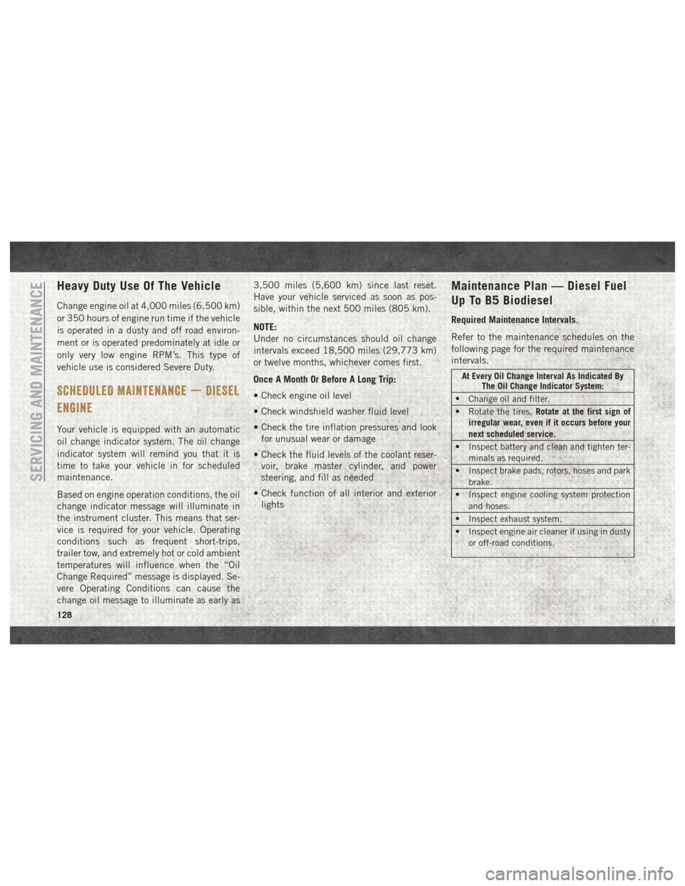
Maintenance Plan — Diesel Fuel
Up To B5 Biodiesel
Required Maintenance Intervals.
Refer to the maintenance schedules on the
following page for the required maintenance
intervals.
At Every Oil Change Interval As Indicated By The Oil Change Indicator System:
• Change oil and filter.
• Rotate the tires. Rotate at the first sign of
irregular wear, even if it occurs before your
next scheduled service.
• Inspect battery and clean and tighten ter- minals as required.
• Inspect brake pads, rotors, hoses and park brake.
• Inspect engine cooling system protection and hoses.
• Inspect exhaust system.
• Inspect engine air cleaner if using in dusty or off-road conditions.
SERVICING AND MAINTENANCE
128
Page 144 of 204

WARNING!
Overloading of your tires is dangerous.
Overloading can cause tire failure, affect
vehicle handling, and increase your stop-
ping distance. Use tires of the recom-
mended load capacity for your vehicle.
Never overload them.
Tires — General Information
Tire Pressure
Proper tire inflation pressure is essential to
the safe and satisfactory operation of your
vehicle. Four primary areas are affected by
improper tire pressure:
• Safety and Vehicle Stability
• Economy
• Tread Wear
• Ride ComfortSafety
WARNING!
• Improperly inflated tires are dangerous
and can cause collisions.
• Underinflation increases tire flexing and
can result in overheating and tire failure.
• Overinflation reduces a tire's ability to cushion shock. Objects on the road and
chuckholes can cause damage that re-
sult in tire failure.
• Overinflated or underinflated tires can
affect vehicle handling and can fail sud-
denly, resulting in loss of vehicle con-
trol.
• Unequal tire pressures can cause steer-
ing problems. You could lose control of
your vehicle.
• Unequal tire pressures from one side of
the vehicle to the other can cause the
vehicle to drift to the right or left.
• Always drive with each tire inflated to
the recommended cold tire inflation
pressure. Both under-inflation and over-inflation affect
the stability of the vehicle and can produce a
feeling of sluggish response or over respon-
siveness in the steering.
NOTE:
• Unequal tire pressures from side to side
may cause erratic and unpredictable steer-
ing response.
• Unequal tire pressure from side to side may cause the vehicle to drift left or right.
Fuel Economy
Underinflated tires will increase tire rolling
resistance resulting in higher fuel consump-
tion.
Tread Wear
Improper cold tire inflation pressures can
cause abnormal wear patterns and reduced
tread life, resulting in the need for earlier tire
replacement.
Ride Comfort And Vehicle Stability
Proper tire inflation contributes to a comfort-
able ride. Over-inflation produces a jarring
and uncomfortable ride.
SERVICING AND MAINTENANCE
142