key Ram ProMaster 2020 User Guide
[x] Cancel search | Manufacturer: RAM, Model Year: 2020, Model line: ProMaster, Model: Ram ProMaster 2020Pages: 264, PDF Size: 10.11 MB
Page 26 of 264

24GETTING TO KNOW YOUR VEHICLE
Daytime Running Lights (DRLs) — If
Equipped
NOTE:
When the headlights are turned on, the Daytime
Running Lights will be deactivated.
To activate the Daytime Running Lights (DRLs),
rotate the end of the multifunction lever to the
O (off) position.
NOTE:
The low beams and side/taillights will not be
on with DRLs.
In certain markets, the DRLs may be optional
and can be programmed to be on or off
through the Uconnect system screen. Refer
to “Uconnect Settings” in “Multimedia” for
further information.
The Daytime Running Lights will come on when -
ever the ignition is ON, the headlight switch is
off, and the turn signal is off.
High Beam/Low Beam Select Switch
With the low beams activated, pull the multi -
function lever toward the steering wheel to
switch the headlights to high beam. A high
beam symbol will be illuminated in the cluster to
indicate the high beams are on. Pull the lever a
second time to switch the headlights back to
low beam.
NOTE:
If the vehicle’s ignition is placed in the STOP
(OFF/LOCK) position, both high and low beam
headlights will also be turned off.
Flash-To-Pass
You can signal another vehicle with your head -
lights by partially pulling the multifunction lever
toward the steering wheel. This will cause the
high beam headlights to turn on until the lever
is released.
Parking Lights
These lights can only be turned on with ignition
key in the STOP (OFF/LOCK) position or
removed, by moving the end of the multifunc -
tion lever to O (off) position and then to the
headlight position. The warning light telltale in the instrument
panel comes on. The lights stay on until the next
ignition cycle is performed.
Follow Me Home/Headlight Delay
When this feature is selected, the driver can
choose to have the headlights remain on for a
preset period of time.
Activation
Remove the key or turn the ignition to the STOP
(OFF/LOCK) position, and pull the multifunction
lever toward the steering wheel, within two
minutes. Each time the lever is pulled, the acti
-
vation of the lights will be extended by 30
seconds. The activation of the lights can be
extended to a maximum of 210 seconds.
The warning light on the instrument panel will
light up and the corresponding message will
appear in the instrument cluster display for as
long as the function is activated. The warning
light comes on when the lever is operated and
stays on until the function is automatically deac -
tivated. Each movement of the lever only
increases the amount of time the lights stay on.
Deactivation
Pull the multifunction lever toward the steering
wheel and hold it for more than two seconds.
20_VF_OM_EN_US_t.book Page 24
Page 29 of 264
GETTING TO KNOW YOUR VEHICLE27
Dimmer Controls
The dimmer controls are located on the left side
of the instrument panel below the instrument
cluster display.
Dimmer Controls
Pushing the up or down arrow will increase or
decrease the brightness of the instrument
panel lights, as long as the headlights are
turned on.
Ambient Light
The vehicle is equipped with ambient light on
the dome lamp. The ambient light will be on all
the time, with the option of dimming it with the
dimmer controls as long as the headlights are
turned on.
Illuminated Entry
The courtesy lights will turn on when you use the
key fob to unlock the doors or open any door.
They also turn on when unlocking or opening
manually from the driver door cylinder.
The lights will fade to off after approximately 30
seconds, or they will immediately fade to off
once the ignition switch is changed to the MAR
(ACC/ON/RUN) position from the STOP (OFF/
LOCK) position.
NOTE:
The front courtesy overhead console and
door courtesy lights will not turn off if the
dimmer control is in the “Dome ON” position.
The illuminated entry system will not operate
if the dimmer control is in the “Dome OFF”
position.
WIPERS AND WASHERS
Front Wiper Operation
The windshield wiper/washer lever is located on
the right side of the steering column. There are
five different modes of operation for the front
windshield wipers. The windshield wiper lever
can be raised or lowered to access the modes.
NOTE:
The windshield wipers/washers will only
operate with the ignition in the MAR (ACC/ON/
RUN) position.
Windshield Wiper/Washer Lever
2
20_VF_OM_EN_US_t.book Page 27
Page 37 of 264
GETTING TO KNOW YOUR VEHICLE35
WINDOWS
Power Windows
The control on the left front door panel has
up-down switches that give you fingertip control
of all power windows. There is a single opening
and closing switch on the front passenger door
for passenger window control.
Power Window Switches
NOTE:
The Key Off Power Delay feature will allow the
power windows to operate for up to three
minutes after the ignition is placed in the STOP
(OFF/LOCK) position. This feature is cancelled
when either front door is opened.
Auto-Down Feature — If Equipped
The window switches may be equipped with an
Auto-Down feature. Push the window switch for
half a second, release, and the window will go
down automatically.
To stop the window from going all the way down
during the auto-down operation, pull up or push
down on the switch briefly.
To open the window part way, lift the window
switch to the detent for less than half a second
and release it to stop the window. NOTE:
The power window switches remain active for
up to three minutes after the ignition switch has
been placed in the STOP (OFF/LOCK) position.
Opening either of the vehicle’s front doors will
cancel this feature.
Auto-Up Feature — If Equipped
The driver window may be equipped with an
Auto-Up feature. This feature is only available
when the ignition is in the MAR (ACC/ON/RUN)
position. Lift the window switch to the detent for
half a second, release, and the window will go
up automatically.
To stop the window from going all the way up
during the auto-up operation, pull up/push
down on the switch briefly.
To close the window part way, lift the window
switch to the detent for less than half a second
and release it when you want the window to
stop.
WARNING!
Never leave children alone in a vehicle, or
with access to an unlocked vehicle.
Allowing children to be in a vehicle unat
-
tended is dangerous for a number of
reasons. A child or others could be seriously
or fatally injured. Children should be
warned not to touch the parking brake,
brake pedal or the gear selector.
Do not leave the key fob in or near the
vehicle or in a location accessible to chil -
dren. A child could operate power windows,
other controls, or move the vehicle.
WARNING!
There is no auto-reverse protection. Be sure
to clear all objects from the window before
closing.
2
20_VF_OM_EN_US_t.book Page 35
Page 41 of 264
GETTING TO KNOW YOUR VEHICLE39
Power Outlets
Passenger Compartment Power Outlet
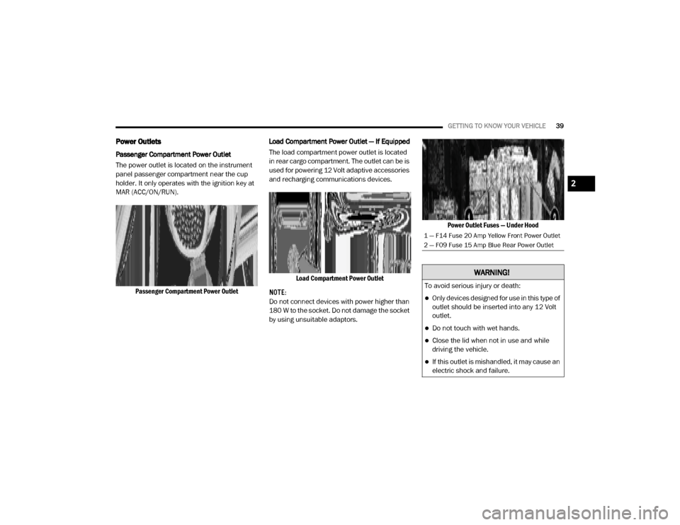
The power outlet is located on the instrument
panel passenger compartment near the cup
holder. It only operates with the ignition key at
MAR (ACC/ON/RUN).
Passenger Compartment Power Outlet Load Compartment Power Outlet — If Equipped
The load compartment power outlet is located
in rear cargo compartment. The outlet can be is
used for powering 12 Volt adaptive accessories
and recharging communications devices.
Load Compartment Power Outlet
NOTE:
Do not connect devices with power higher than
180 W to the socket. Do not damage the socket
by using unsuitable adaptors. Power Outlet Fuses — Under Hood
1 — F14 Fuse 20 Amp Yellow Front Power Outlet
2 — F09 Fuse 15 Amp Blue Rear Power Outlet
WARNING!
To avoid serious injury or death:
Only devices designed for use in this type of
outlet should be inserted into any 12 Volt
outlet.
Do not touch with wet hands.
Close the lid when not in use and while
driving the vehicle.
If this outlet is mishandled, it may cause an
electric shock and failure.
2
20_VF_OM_EN_US_t.book Page 39
Page 65 of 264
SAFETY63
The TPMS is not a substitute for proper tire
maintenance, and it is the driver’s responsi -
bility to maintain correct tire pressure using
an accurate tire pressure gauge, even if
under-inflation has not reached the level to
trigger illumination of the TPMS Warning
Light.
Seasonal temperature changes will affect
tire pressure, and the TPMS will monitor the
actual tire pressure in the tire.
Base System
This is the TPMS warning indicator
located in the instrument cluster.
The TPMS uses wireless technology
with wheel rim mounted electronic
sensors to monitor tire pressure levels.
Sensors, mounted to each wheel as part of the
valve stem, transmit tire pressure readings to
the Receiver Module.
NOTE:
It is particularly important for you to check the
tire pressure in all of the tires on your vehicle
regularly and to maintain the proper pressure.
The TPMS consists of the following components:
Receiver Module
Four Tire Pressure Monitoring sensors
Tire Pressure Monitoring System Warning
Light
Tire Pressure Monitoring Low Pressure Warnings
The Tire Pressure Monitoring System Warning
Light will illuminate in the instrument cluster, an
audible chime will be activated, and the “Check
tire pressure” message will display when one or
more of the four active road tire pressures are
low. Should this occur, you should stop as soon
as possible, check the inflation pressure of
each tire on your vehicle, and inflate each tire to
the vehicle’s recommended cold placard pres
-
sure value. The system will automatically
update and the Tire Pressure Monitoring Light
will extinguish once the updated tire pressures
have been received. The vehicle may need to be
driven for up to 20 minutes above 15 mph
(24 km/h) to receive this information.
Check TPMS Warnings
The Tire Pressure Monitoring System Warning
Light will flash on and off for 75 seconds and
remain on solid when a system fault is detected,
an audible chime will be activated and the “Tire
Pressure Monitoring Unavailable” message will
display. If the ignition key is cycled, this
sequence will repeat providing the system fault
still exists. The TPMS Warning Light will turn off
when the fault condition no longer exists. A
system fault can occur with any of the following
scenarios:
Jamming due to electronic devices or driving
next to facilities emitting the same radio
frequencies as the TPM sensors
Installing some form of aftermarket window
tinting that affects radio wave signals
Snow or ice around the wheels or wheel
housings
Using tire chains on the vehicle
Using wheels/tires not equipped with TPM
sensors
4
20_VF_OM_EN_US_t.book Page 63
Page 66 of 264

64SAFETY
NOTE:
Your vehicle is equipped with a regular size
spare wheel.
1. The spare tire does not have a TPM sensor.
Therefore, the TPMS will not monitor the
pressure in the spare tire.
2. If a spare tire not equipped with the Tire Pressure Monitoring sensor is used, the
TPMS Warning Light will turn on, flashing for
75 seconds and then remaining solid for
each subsequent ignition key cycle.
3. Once you repair or replace the original road tire and reinstall it on the vehicle in place of
the spare tire, the TPMS will update auto -
matically and the Tire Pressure Monitoring
Light will extinguish once the updated tire
pressures have been received. The vehicle
may need to be driven for up to 20 minutes
above 15 mph (24 km/h) to receive this
information.
NOTE:
For correct Tire Pressure Monitoring behavior,
please wait for about 20 minutes in key-off
during each tire substitution.General Information
The following regulatory statement applies to all
Radio Frequency (RF) devices equipped in this
vehicle:
This device complies with Part 15 of the FCC
Rules and with Innovation, Science and
Economic Development Canada license-exempt
RSS standard(s). Operation is subject to the
following two conditions:
1. This device may not cause harmful interfer -
ence, and
2. This device must accept any interference received, including interference that may
cause undesired operation.
Le présent appareil est conforme aux CNR
d`Innovation, Science and Economic Develop -
ment applicables aux appareils radio exempts
de licence. L'exploitation est autorisée aux deux
conditions suivantes:
1. l'appareil ne doit pas produire de brouil -
lage, et
2. l'utilisateur de l'appareil doit accepter tout brouillage radioélectrique subi, même si le
brouillage est susceptible d'en comprom -
ettre le fonctionnement. La operación de este equipo está sujeta a las
siguientes dos condiciones:
1. es posible que este equipo o dispositivo no
cause interferencia perjudicial y
2. este equipo o dispositivo debe aceptar cual -
quier interferencia, incluyendo la que
pueda causar su operación no deseada.
NOTE:
Changes or modifications not expressly
approved by the party responsible for compli -
ance could void the user’s authority to operate
the equipment.
OCCUPANT RESTRAINT SYSTEMS
Some of the most important safety features in
your vehicle are the restraint systems:
Occupant Restraint Systems Features
Seat Belt Systems
Supplemental Restraint Systems (SRS) Air
Bags
Child Restraints
20_VF_OM_EN_US_t.book Page 64
Page 83 of 264
SAFETY81
(Continued)
NOTE:
After an accident, remember to cycle the igni -
tion to the STOP (OFF/LOCK) position and
remove the key from the ignition switch to avoid
draining the battery. Carefully check the vehicle
for fuel leaks in the engine compartment and on
the ground near the engine compartment and
fuel tank before resetting the system and
starting the engine. If there are no fuel leaks or
damage to the vehicle electrical devices (e.g.
headlights) after an accident, reset the Fuel Cut
Off Switch by following the procedure described
below. If you have any doubt, contact an autho -
rized dealer.
Fuel Cut Off Switch Reset Procedure
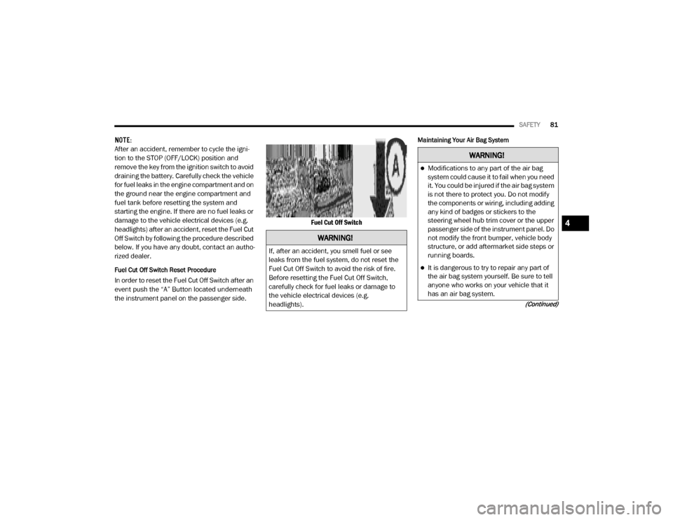
In order to reset the Fuel Cut Off Switch after an
event push the “A” Button located underneath
the instrument panel on the passenger side. Fuel Cut Off Switch
Maintaining Your Air Bag System
WARNING!
If, after an accident, you smell fuel or see
leaks from the fuel system, do not reset the
Fuel Cut Off Switch to avoid the risk of fire.
Before resetting the Fuel Cut Off Switch,
carefully check for fuel leaks or damage to
the vehicle electrical devices (e.g.
headlights).
WARNING!
Modifications to any part of the air bag
system could cause it to fail when you need
it. You could be injured if the air bag system
is not there to protect you. Do not modify
the components or wiring, including adding
any kind of badges or stickers to the
steering wheel hub trim cover or the upper
passenger side of the instrument panel. Do
not modify the front bumper, vehicle body
structure, or add aftermarket side steps or
running boards.
It is dangerous to try to repair any part of
the air bag system yourself. Be sure to tell
anyone who works on your vehicle that it
has an air bag system.
4
20_VF_OM_EN_US_t.book Page 81
Page 93 of 264

SAFETY91
(Continued)
Periodic Safety Checks You Should Make
Outside The Vehicle
Tires
Examine tires for excessive tread wear and
uneven wear patterns. Check for stones, nails,
glass, or other objects lodged in the tread or
sidewall. Inspect the tread for cuts and cracks.
Inspect sidewalls for cuts, cracks, and bulges.
Check the wheel bolts for tightness. Check the
tires (including spare) for proper cold inflation
pressure.
Lights
Have someone observe the operation of brake
lights and exterior lights while you work the
controls. Check turn signal and high beam indi -
cator lights on the instrument panel.
Door Latches
Check for proper closing, latching, and locking.
Fluid Leaks
Check area under the vehicle after overnight
parking for fuel, coolant, oil, or other fluid leaks.
Also, if gasoline fumes are detected or if fuel, or
brake fluid leaks are suspected, the cause
should be located and corrected immediately.
ONLY install floor mats designed to fit your
vehicle. NEVER install a floor mat that
cannot be properly attached and secured to
your vehicle. If a floor mat needs to be
replaced, only use a FCA approved floor
mat for the specific make, model, and year
of your vehicle.
ONLY use the driver’s side floor mat on the
driver’s side floor area. To check for inter -
ference, with the vehicle properly parked
with the engine off, fully depress the accel -
erator, the brake, and the clutch pedal (if
present) to check for interference. If your
floor mat interferes with the operation of
any pedal, or is not secure to the floor,
remove the floor mat from the vehicle and
place the floor mat in your trunk.
ONLY use the passenger’s side floor mat on
the passenger’s side floor area.
WARNING!
(Continued)
ALWAYS make sure objects cannot fall or
slide into the driver’s side floor area when
the vehicle is moving. Objects can become
trapped under accelerator, brake, or clutch
pedals and could cause a loss of vehicle
control.
NEVER place any objects under the floor
mat (e.g., towels, keys, etc.). These objects
could change the position of the floor mat
and may cause interference with the accel -
erator, brake, or clutch pedals.
If the vehicle carpet has been removed and
re-installed, always properly attach carpet
to the floor and check the floor mat
fasteners are secure to the vehicle carpet.
Fully depress each pedal to check for inter -
ference with the accelerator, brake, or
clutch pedals then re-install the floor mats.
It is recommended to only use mild soap
and water to clean your floor mats. After
cleaning, always check your floor mat has
been properly installed and is secured to
your vehicle using the floor mat fasteners
by lightly pulling mat.
WARNING!
(Continued)
4
20_VF_OM_EN_US_t.book Page 91
Page 94 of 264
92
STARTING AND OPERATING
STARTING THE ENGINE
Before starting your vehicle, adjust your seat,
adjust both inside and outside mirrors, and
fasten your seat belts.
Automatic Transmission
The gear selector must be in the PARK or
NEUTRAL position before you can start the
engine. Press the brake pedal before shifting to
any driving gear.
NOTE:
You must press the brake pedal before shifting
out of PARK.
Normal Starting
NOTE:
Normal starting of either a cold or a warm
engine is obtained without pumping or pressing
the accelerator pedal.
Turn the ignition switch to the AVV (START) posi-
tion and release it when the engine starts. If the
engine fails to start within 10 seconds, turn the
ignition switch to the STOP (OFF/LOCK) posi -
tion, wait 10 to 15 seconds, then repeat the
“Normal Starting” procedure.
Cold Weather Operation (Below –22°F Or
−30°C)
To ensure reliable starting at these tempera -
tures, use of an externally powered electric
engine block heater (available from your autho -
rized dealer) is recommended.
If Engine Fails To Start
If the engine fails to start after you have
followed the “Normal Starting” procedure, it
may be flooded. Push the accelerator pedal all
the way to the floor and hold it there. Crank the
engine for no more than 15 seconds. This
should clear any excess fuel in case the engine
is flooded. Leave the ignition key in the RUN
position, release the accelerator pedal and
repeat the “Normal Starting” procedure.
WARNING!
Never leave children alone in a vehicle, or
with access to an unlocked vehicle.
Allowing children to be in a vehicle unat -
tended is dangerous for a number of
reasons. A child or others could be seriously
or fatally injured. Children should be
warned not to touch the parking brake,
brake pedal or the transmission gear
selector.
Do not leave the key fob in or near the
vehicle (or in a location accessible to chil -
dren). A child could operate power
windows, other controls, or move the
vehicle.
20_VF_OM_EN_US_t.book Page 92
Page 97 of 264
STARTING AND OPERATING95
(Continued)
AUTOMATIC TRANSMISSION
Do not leave the key fob in or near the
vehicle, or in a location accessible to chil-
dren, and do not leave a vehicle equipped
with Keyless Enter-N-Go in the ACC or ON/
RUN mode. A child could operate power
windows, other controls, or move the
vehicle.
Be sure the parking brake is fully disen -
gaged before driving; failure to do so can
lead to brake failure and a collision.
Always fully apply the parking brake when
leaving your vehicle or it may roll and cause
damage or injury. Also, be certain to leave
the transmission in PARK. Failure to do so
may cause the vehicle to roll and cause
damage or injury.
CAUTION!
If the Brake System Warning Light remains on
with the parking brake released, a brake
system malfunction is indicated. Have the
brake system serviced by an authorized
dealer immediately.
WARNING!
(Continued)
WARNING!
It is dangerous to shift out of PARK or
NEUTRAL if the engine speed is higher than
idle speed. If your foot is not firmly pressing
the brake pedal, the vehicle could accel -
erate quickly forward or in reverse. You
could lose control of the vehicle and hit
someone or something. Only shift into gear
when the engine is idling normally and your
foot is firmly pressing the brake pedal.
Unintended movement of a vehicle could
injure those in or near the vehicle. As with
all vehicles, you should never exit a vehicle
while the engine is running. Before exiting a
vehicle always come to a complete stop,
then apply the parking brake, shift the
transmission into PARK, turn the engine
OFF, and remove the ignition key. Once the
key is removed, the transmission is locked
in PARK, securing the vehicle against
unwanted movement.
When leaving the vehicle, always remove
the ignition key from the vehicle and lock
the vehicle.
Never leave children alone in a vehicle, or
with access to an unlocked vehicle.
Allowing children to be in a vehicle unat -
tended is dangerous for a number of
reasons. A child or others could be seriously
or fatally injured. Children should be
warned not to touch the parking brake,
brake pedal or the transmission gear
selector.
Do not leave the ignition key in or near the
vehicle (or in a location accessible to chil -
dren). A child could operate power
windows, other controls, or move the
vehicle.
WARNING!
(Continued)
5
20_VF_OM_EN_US_t.book Page 95