light Ram ProMaster 2020 Repair Manual
[x] Cancel search | Manufacturer: RAM, Model Year: 2020, Model line: ProMaster, Model: Ram ProMaster 2020Pages: 264, PDF Size: 10.11 MB
Page 129 of 264
IN CASE OF EMERGENCY127
3. Remove the two (2) 17mm tail light
assembly fasteners.
4. Disconnect the tail light harness connector and remove tail light assembly from the
vehicle.
5. Remove the tail/stop, turn signal, backup and rear side marker bulb/socket by
rotating counterclockwise.
6. Remove the bulb and replace as needed.
7. Reinstall bulb/socket and rotate clockwise to lock in place.
8. Reinstall lamp.
Replacing Interior Bulbs
Cargo Lamp
1. Using a suitable tool, remove either the lamp above the back door or the sliding
door lamp as needed and disconnect it. Rear Cargo Lamp Bulb Access
2. Using a suitable tool, pull open the metal bulb access on the back of the housing.
Cargo Lamp Bulb Location 3. Remove and install the replacement bulb.
4. Close the bulb access, connect the lamp
and install the lamp into place.
Dome Lamps
1. Using a suitable tool, insert the tip at thelocation shown and press inward to the
lamp to relieve the spring tension. This will
allow you to easily drop the dome lamp
assembly from its bracket and disconnect
the lamp.
Dome Lamp Assembly Location
1 — Spring Tension Relief Access
2 — Dome Lamp Assembly
6
20_VF_OM_EN_US_t.book Page 127
Page 130 of 264
128IN CASE OF EMERGENCY
(Continued)
2. Using a suitable tool, flex the housing to lift
the light pod cover away from the unit.
Dome Lamp Light Pod Cover
3. Remove and replace the bulbs as needed.
Dome Lamp Light Bulbs 4. Close the housing cover making sure it
snaps together properly and connect the
lamp.
5. Install overhead console into place making sure to seat the assembly’s forward end
first and then snapping it flush so that the
tension spring is fully seating in the housing.
FUSESUnderhood Fuses
The Front Power Distribution Center is located
on the driver’s side of the engine compartment.
To access the fuses, remove the cover.
Front Power Distribution Center
The ID number of the electrical component
corresponding to each fuse can be found on the
back of the cover.WARNING!
When replacing a blown fuse, always use
an appropriate replacement fuse with the
same amp rating as the original fuse. Never
replace a fuse with another fuse of higher
amp rating. Never replace a blown fuse with
metal wires or any other material. Do not
place a fuse inside a circuit breaker cavity
or vice versa. Failure to use proper fuses
may result in serious personal injury, fire
and/or property damage.
Before replacing a fuse, make sure that the
ignition is off and that all the other services
are switched off and/or disengaged.
If the replaced fuse blows again, contact an
authorized dealer.
If a general protection fuse for safety
systems (air bag system, braking system),
power unit systems (engine system, trans -
mission system) or steering system blows,
contact an authorized dealer.
WARNING!
(Continued)
20_VF_OM_EN_US_t.book Page 128
Page 133 of 264
IN CASE OF EMERGENCY131
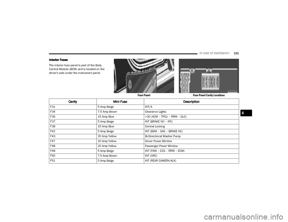
Interior Fuses
The interior fuse panel is part of the Body
Control Module (BCM) and is located on the
driver's side under the instrument panel.
Fuse PanelFuse Panel Cavity Locations
CavityMini Fuse Description
F315 Amp BeigeINT/A
F34 7.5 Amp BrownClearance Lights
F36 15 Amp Blue+30 (ACM – TPCU – RRM – DLC)
F37 5 Amp BeigeINT (BRAKE NO – IPC)
F38 15 Amp BlueCentral Locking
F42 5 Amp BeigeINT (BSM – SAS – BRAKE NC)
F43 20 Amp YellowBi-Directional Washer Pump
F47 20 Amp YellowDriver Power Window
F48 20 Amp YellowPassenger Power Window
F49 5 Amp BeigeINT (PAM – CCS – RRM – ECM)
F50 7.5 Amp BrownINT (ORC)
F51 5 Amp BeigeINT (REAR CAMERA-AUX)
6
20_VF_OM_EN_US_t.book Page 131
Page 140 of 264
138IN CASE OF EMERGENCY
Rear Lifting Point
Rear Jacking Location
NOTE:
The front jacking location is located behind the
front tire and in front of the driver/passenger
door. 3. Place the wrench handle and lug bolt
adapter on the jack screw and turn clock -
wise until the jack head is properly engaged
in the described location. Do not raise the
vehicle until you are sure the jack is
securely engaged.
4. Raise the vehicle by turning the jack screw clockwise, using the wrench handle and lug
bolt adapter. Raise the vehicle only until the
tire just clears the surface and enough
clearance is obtained to install the spare
tire. Minimum tire lift provides maximum
stability. 5. Remove the wheel lug bolts. For vehicles
with wheel covers, remove the cover from
the wheel by hand. Do not pry the wheel
cover off. Then pull the wheel off the hub.
6. Install the spare tire. Lightly tighten the wheel lug bolts.
Mounting Spare Tire
WARNING!
Being under a jacked-up vehicle is
dangerous. The vehicle could slip off the jack
and fall on you. You could be crushed. Never
get any part of your body under a vehicle that
is on a jack. If you need to get under a raised
vehicle, take it to a service center where it
can be raised on a lift.
WARNING!
Raising the vehicle higher than necessary can
make the vehicle less stable. It could slip off
the jack and hurt someone near it. Raise the
vehicle only enough to remove the tire.
20_VF_OM_EN_US_t.book Page 138
Page 154 of 264
152
SERVICING AND MAINTENANCE
SCHEDULED SERVICING
Your vehicle is equipped with an automatic oil
change indicator system. The oil change indi-
cator system will remind you that it is time to
take your vehicle in for scheduled maintenance.
Based on engine operation conditions, the oil
change indicator message will illuminate in the
instrument cluster. This means that service is
required for your vehicle. Operating conditions
such as frequent short-trips, trailer tow, and
extremely hot or cold ambient temperatures will
influence when the “Oil Change Required”
message is displayed. Severe Operating Condi-
tions can cause the change oil message to illu -
minate as early as 3,500 miles (5,600 km)
since last reset. Have the vehicle serviced as
soon as possible, within the next 500 miles
(805 km). An authorized dealer will reset the oil change
indicator message after completing the sched
-
uled oil change. If a scheduled oil change is
performed by someone other than an autho -
rized dealer, the message can be reset by refer -
ring to the steps described under “Instrument
Cluster Display” in “Getting To Know Your
Instrument Panel” for further information.
NOTE:
Under no circumstances should oil change
intervals exceed 10,000 miles (16,000 km),
12 months or 350 hours of engine run time,
whichever comes first. The 350 hours of engine
run or idle time is generally only a concern for
fleet customers.
Severe Duty All Models
Change Engine Oil at 4,000 miles (6,500 km) or
350 hours of engine run time if the vehicle is
operated in a dusty and off road environment or
is operated predominately at idle or only very
low engine RPM. This type of vehicle use is
considered Severe Duty. Once A Month Or Before A Long Trip:Check engine oil level
Check windshield washer fluid level
Check the tire inflation pressures and look
for unusual wear or damage. Rotate at the
first sign of irregular wear, even if it occurs
before the oil indicator system turns on
Check the fluid levels of the coolant reservoir,
brake master cylinder, and power steering
and fill as needed
Check function of all interior and exterior
lights
Maintenance Plan
Required Maintenance Intervals
Refer to the maintenance plan on the following
pages for the required maintenance intervals.
20_VF_OM_EN_US_t.book Page 152
Page 159 of 264
SERVICING AND MAINTENANCE157
Checking Oil Level — Gas Engine
To ensure proper lubrication of your vehicle's
engine, the engine oil must be maintained at
the correct level. Check the oil level at regular
intervals, such as every fuel stop. The best time
to check the engine oil level is about five
minutes after a fully warmed up engine is shut
off.
Checking the oil while the vehicle is on level
ground will improve the accuracy of the oil level
readings. Always maintain the oil level within
the SAFE zone on the dipstick. Adding one quart
of oil when the reading is at the bottom of the
SAFE zone will result in a reading at the top of
the safe zone on these engines.
Adding Washer Fluid
The fluid reservoir is located in the engine
compartment and should be checked at regular
intervals. Fill the reservoir with windshield
washer solvent (not radiator antifreeze) and
operate the system for a few seconds to flush
out any residual water.
The washer fluid reservoir will hold a full gallon
of fluid when the Low Washer Fluid Light illumi -
nates.
After the engine has warmed, operate the
defroster for a few minutes to reduce the possi -
bility of smearing or freezing the fluid on the
cold windshield. Mopar All Weather Windshield
Washer Solution or equivalent, used with water
as directed on the container, aids cleaning
action, reduces the freezing point to avoid line
clogging, and is not harmful to paint or trim.
Maintenance-Free Battery
Your vehicle is equipped with a mainte-
nance-free battery. You will never have to add
water, nor is periodic maintenance required.
CAUTION!
Overfilling or underfilling will cause oil
aeration or loss of oil pressure. This could
damage your engine.
WARNING!
Commercially available windshield washer
solvents are flammable. They could ignite and
burn you. Care must be exercised when filling
or working around the washer solution.
WARNING!
Battery fluid is a corrosive acid solution and
can burn or even blind you. Do not allow
battery fluid to contact your eyes, skin, or
clothing. Do not lean over a battery when
attaching clamps. If acid splashes in eyes
or on skin, flush the area immediately with
large amounts of water. Refer to “Jump
Starting Procedure” in “In Case Of Emer -
gency” for further information.
Battery gas is flammable and explosive.
Keep flame or sparks away from the
battery. Do not use a booster battery or any
other booster source with an output greater
than 12 Volts. Do not allow cable clamps to
touch each other.
Battery posts, terminals, and related acces -
sories contain lead and lead compounds.
Wash hands after handling.
7
20_VF_OM_EN_US_t.book Page 157
Page 171 of 264
SERVICING AND MAINTENANCE169
NOTE:
P (Passenger) — Metric tire sizing is based on
US design standards. P-Metric tires have the
letter “P” molded into the sidewall preceding
the size designation. Example: P215/65R15
95H.
European — Metric tire sizing is based on
European design standards. Tires designed
to this standard have the tire size molded into the sidewall beginning with the section
width. The letter "P" is absent from this tire
size designation. Example: 215/65R15 96H.
LT (Light Truck) — Metric tire sizing is based
on US design standards. The size designation
for LT-Metric tires is the same as for P-Metric
tires except for the letters “LT” that are
molded into the sidewall preceding the size
designation. Example: LT235/85R16.
Temporary spare tires are designed for
temporary emergency use only. Temporary
high pressure compact spare tires have the
letter “T” or “S” molded into the sidewall
preceding the size designation. Example:
T145/80D18 103M.
High flotation tire sizing is based on US
design standards and it begins with the tire
diameter molded into the sidewall. Example:
31x10.5 R15 LT.
Tire Sizing Chart
EXAMPLE:
Example Size Designation: P215/65R15XL 95H, 215/65R15 96H, LT235/85R16C, T145/80D18 103M, 31x10.5 R15 LT
P = Passenger car tire size based on US design standards, or
"....blank...."
= Passenger car tire based on European design standards, or
LT = Light truck tire based on US design standards, or
T or S = Temporary spare tire or
31 = Overall diameter in inches (in)
215, 235, 145 = Section width in millimeters (mm)
65, 85, 80 = Aspect ratio in percent (%)
Ratio of section height to section width of tire, or
10.5 = Section width in inches (in)
7
20_VF_OM_EN_US_t.book Page 169
Page 172 of 264

170SERVICING AND MAINTENANCE
R = Construction code
"R" means radial construction, or
"D" means diagonal or bias construction
15, 16, 18 = Rim diameter in inches (in)
Service Description:
95 = Load Index
A numerical code associated with the maximum load a tire can carry
H = Speed Symbol
A symbol indicating the range of speeds at which a tire can carry a load corresponding to its load index under certain operating conditions
The maximum speed corresponding to the speed symbol should only be achieved under specified operating conditions (i.e., tire pressure, vehicle
loading, road conditions, and posted speed limits)
Load Identification:
Absence of the following load identification symbols on the sidewall of the tire indicates a Standard Load (SL) tire:
XL = Extra load (or reinforced) tire, or
LL = Light load tire or
C, D, E, F, G = Load range associated with the maximum load a tire can carry at a specified pressure
Maximum Load – Maximum load indicates the maximum load this tire is designed to carry
Maximum Pressure – Maximum pressure indicates the maximum permissible cold tire inflation pressure for this tire
EXAMPLE:
20_VF_OM_EN_US_t.book Page 170
Page 181 of 264
SERVICING AND MAINTENANCE179
Tread Wear Indicators
Tread wear indicators are in the original equip -
ment tires to help you in determining when your
tires should be replaced.
Tire Tread
These indicators are molded into the bottom of
the tread grooves. They will appear as bands
when the tread depth becomes a 1/16 of an
inch (1.6 mm). When the tread is worn to the
tread wear indicators, the tire should be
replaced.
Refer to “Replacement Tires” in this section for
further information.
Life Of Tire
The service life of a tire is dependent upon
varying factors including, but not limited to:
Driving style.
Tire pressure - Improper cold tire inflation
pressures can cause uneven wear patterns
to develop across the tire tread. These
abnormal wear patterns will reduce tread life,
resulting in the need for earlier tire replace -
ment.
Distance driven.
Performance tires, tires with a speed rating of
V or higher, and Summer tires typically have
a reduced tread life. Rotation of these tires
per the vehicle scheduled maintenance is
highly recommended. NOTE:
Wheel Valve Stem must be replaced as well
when installing new tires due to wear and tear
in existing tires.
Keep dismounted tires in a cool, dry place with
as little exposure to light as possible. Protect
tires from contact with oil, grease, and gasoline.
Replacement Tires
The tires on your new vehicle provide a balance
of many characteristics. They should be
inspected regularly for wear and correct cold
tire inflation pressures. The manufacturer
strongly recommends that you use tires equiva-
lent to the originals in size, quality and perfor
-
mance when replacement is needed. Refer to
the paragraph on “Tread Wear Indicators” in
this section. Refer to the Tire and Loading Infor -
mation placard or the Vehicle Certification Label
for the size designation of your tire. The Load
Index and Speed Symbol for your tire will be
found on the original equipment tire sidewall.
See the Tire Sizing Chart example found in the
“Tire Safety Information” section of this manual
for more information relating to the Load Index
and Speed Symbol of a tire.
1 — Worn Tire
2 — New Tire
WARNING!
Tires and the spare tire should be replaced
after six years, regardless of the remaining
tread. Failure to follow this warning can result
in sudden tire failure. You could lose control
and have a collision resulting in serious injury
or death.
7
20_VF_OM_EN_US_t.book Page 179
Page 186 of 264
184SERVICING AND MAINTENANCE
(Continued)
NOTE:
If you intend parking or storing your vehicle for
an extended period after cleaning the wheels
with wheel cleaner, drive your vehicle and apply
the brakes to remove the water droplets from
the brake components. This activity will remove
the red rust on the brake rotors and prevent
vehicle vibration when braking. Dark Vapor Chrome, Black Satin Chrome, or
Low Gloss Clear Coat Wheels
Tire Chains And Traction Devices
Use of traction devices require sufficient
tire-to-body clearance. Due to limited clearance
the following traction devices are recom
-
mended. Follow these recommendations to
guard against damage.
Traction device must be of proper size for the
tire, as recommended by the traction device
manufacturer.
No other tire sizes are recommended for use
with a tire chain or traction device.
Install on front tires only.
For LT225/75R16 and 215/75R16C tires
use of a Quality Chain Corp Light Truck
Highway Service (Non-Cam) tire chain or
equivalent snow traction device is recom -
mended.
CAUTION!
Do not use scouring pads, steel wool, a bristle
brush, metal polishes or oven cleaner. These
products may damage the wheel's protective
finish. Such damage is not covered by the
New Vehicle Limited Warranty. Only car wash
soap, Mopar Wheel Cleaner or equivalent is
recommended.CAUTION!
If your vehicle is equipped with these
specialty wheels, DO NOT USE wheel
cleaners, abrasives, or polishing compounds.
They will permanently damage this finish and
such damage is not covered by the New
Vehicle Limited Warranty. HAND WASH ONLY
USING MILD SOAP AND WATER WITH A SOFT
CLOTH. Used on a regular basis; this is all that
is required to maintain this finish.
WARNING!
Using tires of different size and type (M+S,
Snow) between front and rear axles can
cause unpredictable handling. You could lose
control and have a collision.
CAUTION!
To avoid damage to your vehicle or tires,
observe the following precautions:
Because of restricted traction device clear -
ance between tires and other suspension
components, it is important that only trac-
tion devices in good condition are used.
Broken devices can cause serious damage.
Stop the vehicle immediately if noise
occurs that could indicate device breakage.
Remove the damaged parts of the device
before further use.
20_VF_OM_EN_US_t.book Page 184