change wheel Ram ProMaster 2020 Owner's Manual
[x] Cancel search | Manufacturer: RAM, Model Year: 2020, Model line: ProMaster, Model: Ram ProMaster 2020Pages: 264, PDF Size: 10.11 MB
Page 4 of 264

2
INTRODUCTION
INTRODUCTION ......................................................... 7
HOW TO USE THIS MANUAL ................................... 8
Essential Information ........................................... 8
Symbols ................................................................. 8
WARNINGS AND CAUTIONS ................................... 8
VAN CONVERSIONS/CAMPERS .............................. 8
VEHICLE MODIFICATIONS/ALTERATIONS ............. 8
GETTING TO KNOW YOUR VEHICLE
KEYS .......................................................................... 9
Key Fob ................................................................. 9
IGNITION SWITCH ................................................... 11
Mechanical Ignition Switch ................................ 11
Key-In-Ignition Reminder ................................... 12
SENTRY KEY............................................................. 12
Replacement Keys ............................................ 12
General Information ........................................... 12
VEHICLE SECURITY ALARM — IF EQUIPPED ....... 13
To Arm The System ............................................. 13
To Disarm The System ....................................... 13
Rearming Of The System ................................... 14
Security System Manual Override ..................... 14
DOORS ..................................................................... 14
Power Door Locks .............................................. 14
Auto Unlock Doors .............................................. 15
Automatic Door Locks ........................................ 15
SEATS .......................................................................15
Manual Adjustments .......................................... 15
Heated Seats — If Equipped .............................. 18
Fold Down Tray — If Equipped ........................... 19
Adjustable Armrests — If Equipped ................... 19
HEAD RESTRAINTS ................................................20
Front Head Restraint Adjustment ..................... 20
Front Head Restraint Removal .......................... 20
STEERING WHEEL ...................................................21
Telescoping Steering Column ............................ 21
MIRRORS .................................................................21
Inside Day/Night Mirror — If Equipped ............ 21
Outside Mirrors .................................................. 21
Power Mirrors — If Equipped ............................. 22
Power Folding Mirrors — If Equipped ................ 22
Heated Mirrors — If Equipped............................ 23
EXTERIOR LIGHTS ...................................................23
Multifunction Lever ........................................... 23
Headlights .......................................................... 23
Daytime Running Lights (DRLs) —
If Equipped ......................................................... 24 High Beam/Low Beam Select Switch .............. 24
Flash-To-Pass ..................................................... 24
Parking Lights .................................................... 24
Follow Me Home/Headlight Delay .................... 24
Fog Lights — If Equipped ................................... 25
Turn Signals ........................................................ 25
Lane Change Assist............................................ 25
Battery Saver ...................................................... 25
INTERIOR LIGHTS ................................................... 25
Courtesy Lights....................................................25
Illuminated Entry .................................................27
WIPERS AND WASHERS ........................................ 27
Front Wiper Operation .......................................27
CLIMATE CONTROLS .............................................. 28
Manual Climate Control Overview......................28
Climate Control Functions ..................................33
Operating Tips .....................................................33
WINDOWS ............................................................... 35
Power Windows ..................................................35
Window Bar Grates — If Equipped .....................36
Wind Buffeting ....................................................36
HOOD ........................................................................ 36
Opening ...............................................................36
Closing .................................................................37
CARGO AREA FEATURES ....................................... 37
INTERNAL EQUIPMENT .......................................... 37
Storage ................................................................37
Cupholders ..........................................................38
Power Outlets ......................................................39
Auxiliary Switches — If Equipped ........................40
20_VF_OM_EN_US_t.book Page 2
Page 5 of 264

3
GETTING TO KNOW YOUR INSTRUMENT
PANEL
INSTRUMENT CLUSTER .......................................... 41
Instrument Cluster Descriptions........................ 42
INSTRUMENT CLUSTER DISPLAY ......................... 43
Location And Controls ........................................ 43
Change Engine Oil .............................................. 44
Display Setup Menu ........................................... 44
Values Displayed ................................................ 45
Personal Settings (Customer-Programmable
Features) ............................................................. 46
TRIP COMPUTER ..................................................... 46
Trip Button .......................................................... 46
Trip Functions ..................................................... 46
WARNING LIGHTS AND MESSAGES ..................... 47
Red Warning Lights ............................................ 47
Yellow Warning Lights ........................................ 50
Yellow Indicator Lights ....................................... 52
Green Indicator Lights ........................................ 53
Blue Indicator Lights .......................................... 53
ONBOARD DIAGNOSTIC SYSTEM — OBD II ........ 54
Onboard Diagnostic System (OBD II)
Cybersecurity ...................................................... 54
EMISSIONS INSPECTION AND MAINTENANCE
PROGRAMS ............................................................. 55
SAFETY
SAFETY FEATURES ..................................................56
Four-Wheel Anti-Lock Brake System (ABS) ....... 56
Electronic Brake Control (EBC) System ........... 57
AUXILIARY DRIVING SYSTEMS ..............................61
Tire Pressure Monitoring System (TPMS) ......... 61
OCCUPANT RESTRAINT SYSTEMS .......................64
Occupant Restraint Systems Features ............ 64
Important Safety Precautions............................ 65
Seat Belt Systems ............................................. 66
Supplemental Restraint Systems (SRS) ........... 73
Child Restraints .................................................. 83
Transporting Pets .............................................. 89
SAFETY TIPS ............................................................89
Transporting Passengers ................................... 89
Exhaust Gas ........................................................ 89
Safety Checks You Should Make Inside
The Vehicle ........................................................ 90 Periodic Safety Checks You Should Make
Outside The Vehicle ........................................... 91
STARTING AND OPERATING
STARTING THE ENGINE ..........................................92
Automatic Transmission .................................... 92
Normal Starting .................................................. 92
Cold Weather Operation
(Below –22°F Or −30°C) ................................. 92 If Engine Fails To Start ....................................... 92
After Starting ...................................................... 93
ENGINE BLOCK HEATER — IF EQUIPPED ............ 93
ENGINE BREAK-IN RECOMMENDATIONS ........... 93
PARKING BRAKE ................................................... 94
AUTOMATIC TRANSMISSION ................................ 95
Key Ignition Park Interlock .................................96
Brake/Transmission Shift Interlock System ....96
Six-Speed Automatic Transmission ...................96
POWER STEERING ............................................... 102
Power Steering Fluid Check ........................... 103
SPEED CONTROL — IF EQUIPPED ......................103
To Activate ........................................................ 103
To Set A Desired Speed ................................... 104
To Vary The Speed Setting .............................. 104
To Accelerate For Passing ............................... 105
To Resume Speed ............................................ 105
To Deactivate ................................................... 105
PARKSENSE REAR PARK ASSIST —
IF EQUIPPED ..........................................................105
ParkSense Rear Park Assist Sensors ............. 106
ParkSense Rear Park Assist Alerts ................. 106
ParkSense Rear Park Assist Failure
Indications ........................................................ 108 Cleaning The ParkSense System .................... 108
ParkSense Rear Park Assist System Usage
Precautions ...................................................... 108
PARKVIEW REAR BACK UP CAMERA ............... 109
REFUELING THE VEHICLE.....................................111
Loose Fuel Filler Cap Message ....................... 111
20_VF_OM_EN_US_t.book Page 3
Page 32 of 264
30GETTING TO KNOW YOUR VEHICLE
Blower Control
Blower Control regulates the amount of air forced through the climate system. There are seven blower speeds available.
The blower speed increases as you turn the blower control knob clockwise from the lowest blower setting. The blower
speed decreases as you turn the blower control knob counterclockwise.
NOTE:
Depending on the configuration, your vehicle may be equipped with four blower speeds.
Mode Control
Turn the mode control knob to change the airflow distribution mode. The airflow distribution mode can be adjusted so air
comes from the instrument panel outlets, floor outlets, defrost outlets and demist outlets. The Mode settings are as
follows:
Panel Mode Panel Mode Air comes from the outlets in the instrument panel. Each of these outlets can be individually adjusted to direct the flow of
air. The air vanes of the center outlets and outboard outlets can be moved up and down or side to side to regulate airflow
direction. There is a shut off wheel located below the air vents to shut off or adjust the amount of airflow from these
outlets.
Icon Description
20_VF_OM_EN_US_t.book Page 30
Page 60 of 264
58SAFETY
(Continued)
ESC Operating Modes
The “ESC OFF” switch is located in the
center switch bank, next to the hazard
flasher switch.
ESC On
This mode is the normal operating mode for ESC
equipped vehicles. Whenever the vehicle is
started, the ESC system will be in this mode.
This mode should be used for most driving situ -
ations. ESC should only be turned off for
specific reasons as noted below.
ESC Partial Off
This mode is entered by momentarily pushing
the “ESC OFF” switch.
When in the “Partial Off” mode, the TCS portion
of ESC, except for the “limited slip” feature
described in the TCS section, has been disabled
and the “ESC OFF Indicator Light” will be illumi-
nated. When in the “Partial Off” mode, ESC will
operate without engine torque management.
This mode is intended to be used if the vehicle is
in deep snow, sand or gravel conditions and
more wheel spin than ESC would normally allow
is required to gain traction. To turn ESC on again,
momentarily push the “ESC OFF” switch. This will
restore the normal “ESC On” mode of operation.
WARNING!
Electronic Stability Control (ESC) cannot
prevent the natural laws of physics from
acting on the vehicle, nor can it increase
the traction afforded by prevailing road
conditions. ESC cannot prevent acci -
dents, including those resulting from
excessive speed in turns, driving on very
slippery surfaces, or hydroplaning. ESC
also cannot prevent accidents resulting
from loss of vehicle control due to inap -
propriate driver input for the conditions.
Only a safe, attentive, and skillful driver
can prevent accidents. The capabilities of
an ESC equipped vehicle must never be
exploited in a reckless or dangerous
manner which could jeopardize the user’s
safety or the safety of others.Vehicle modifications, or failure to properly
maintain your vehicle, may change the
handling characteristics of your vehicle,
and may negatively affect the performance
of the ESC system. Changes to the steering
system, suspension, braking system, tire
type and size or wheel size may adversely
affect ESC performance. Improperly
inflated and unevenly worn tires may also
degrade ESC performance. Any vehicle
modification or poor vehicle maintenance
that reduces the effectiveness of the ESC
system can increase the risk of loss of
vehicle control, vehicle rollover, personal
injury and death.
WARNING!
(Continued)
20_VF_OM_EN_US_t.book Page 58
Page 65 of 264
SAFETY63
The TPMS is not a substitute for proper tire
maintenance, and it is the driver’s responsi -
bility to maintain correct tire pressure using
an accurate tire pressure gauge, even if
under-inflation has not reached the level to
trigger illumination of the TPMS Warning
Light.
Seasonal temperature changes will affect
tire pressure, and the TPMS will monitor the
actual tire pressure in the tire.
Base System
This is the TPMS warning indicator
located in the instrument cluster.
The TPMS uses wireless technology
with wheel rim mounted electronic
sensors to monitor tire pressure levels.
Sensors, mounted to each wheel as part of the
valve stem, transmit tire pressure readings to
the Receiver Module.
NOTE:
It is particularly important for you to check the
tire pressure in all of the tires on your vehicle
regularly and to maintain the proper pressure.
The TPMS consists of the following components:
Receiver Module
Four Tire Pressure Monitoring sensors
Tire Pressure Monitoring System Warning
Light
Tire Pressure Monitoring Low Pressure Warnings
The Tire Pressure Monitoring System Warning
Light will illuminate in the instrument cluster, an
audible chime will be activated, and the “Check
tire pressure” message will display when one or
more of the four active road tire pressures are
low. Should this occur, you should stop as soon
as possible, check the inflation pressure of
each tire on your vehicle, and inflate each tire to
the vehicle’s recommended cold placard pres
-
sure value. The system will automatically
update and the Tire Pressure Monitoring Light
will extinguish once the updated tire pressures
have been received. The vehicle may need to be
driven for up to 20 minutes above 15 mph
(24 km/h) to receive this information.
Check TPMS Warnings
The Tire Pressure Monitoring System Warning
Light will flash on and off for 75 seconds and
remain on solid when a system fault is detected,
an audible chime will be activated and the “Tire
Pressure Monitoring Unavailable” message will
display. If the ignition key is cycled, this
sequence will repeat providing the system fault
still exists. The TPMS Warning Light will turn off
when the fault condition no longer exists. A
system fault can occur with any of the following
scenarios:
Jamming due to electronic devices or driving
next to facilities emitting the same radio
frequencies as the TPM sensors
Installing some form of aftermarket window
tinting that affects radio wave signals
Snow or ice around the wheels or wheel
housings
Using tire chains on the vehicle
Using wheels/tires not equipped with TPM
sensors
4
20_VF_OM_EN_US_t.book Page 63
Page 66 of 264

64SAFETY
NOTE:
Your vehicle is equipped with a regular size
spare wheel.
1. The spare tire does not have a TPM sensor.
Therefore, the TPMS will not monitor the
pressure in the spare tire.
2. If a spare tire not equipped with the Tire Pressure Monitoring sensor is used, the
TPMS Warning Light will turn on, flashing for
75 seconds and then remaining solid for
each subsequent ignition key cycle.
3. Once you repair or replace the original road tire and reinstall it on the vehicle in place of
the spare tire, the TPMS will update auto -
matically and the Tire Pressure Monitoring
Light will extinguish once the updated tire
pressures have been received. The vehicle
may need to be driven for up to 20 minutes
above 15 mph (24 km/h) to receive this
information.
NOTE:
For correct Tire Pressure Monitoring behavior,
please wait for about 20 minutes in key-off
during each tire substitution.General Information
The following regulatory statement applies to all
Radio Frequency (RF) devices equipped in this
vehicle:
This device complies with Part 15 of the FCC
Rules and with Innovation, Science and
Economic Development Canada license-exempt
RSS standard(s). Operation is subject to the
following two conditions:
1. This device may not cause harmful interfer -
ence, and
2. This device must accept any interference received, including interference that may
cause undesired operation.
Le présent appareil est conforme aux CNR
d`Innovation, Science and Economic Develop -
ment applicables aux appareils radio exempts
de licence. L'exploitation est autorisée aux deux
conditions suivantes:
1. l'appareil ne doit pas produire de brouil -
lage, et
2. l'utilisateur de l'appareil doit accepter tout brouillage radioélectrique subi, même si le
brouillage est susceptible d'en comprom -
ettre le fonctionnement. La operación de este equipo está sujeta a las
siguientes dos condiciones:
1. es posible que este equipo o dispositivo no
cause interferencia perjudicial y
2. este equipo o dispositivo debe aceptar cual -
quier interferencia, incluyendo la que
pueda causar su operación no deseada.
NOTE:
Changes or modifications not expressly
approved by the party responsible for compli -
ance could void the user’s authority to operate
the equipment.
OCCUPANT RESTRAINT SYSTEMS
Some of the most important safety features in
your vehicle are the restraint systems:
Occupant Restraint Systems Features
Seat Belt Systems
Supplemental Restraint Systems (SRS) Air
Bags
Child Restraints
20_VF_OM_EN_US_t.book Page 64
Page 93 of 264
SAFETY91
(Continued)
Periodic Safety Checks You Should Make
Outside The Vehicle
Tires
Examine tires for excessive tread wear and
uneven wear patterns. Check for stones, nails,
glass, or other objects lodged in the tread or
sidewall. Inspect the tread for cuts and cracks.
Inspect sidewalls for cuts, cracks, and bulges.
Check the wheel bolts for tightness. Check the
tires (including spare) for proper cold inflation
pressure.
Lights
Have someone observe the operation of brake
lights and exterior lights while you work the
controls. Check turn signal and high beam indi -
cator lights on the instrument panel.
Door Latches
Check for proper closing, latching, and locking.
Fluid Leaks
Check area under the vehicle after overnight
parking for fuel, coolant, oil, or other fluid leaks.
Also, if gasoline fumes are detected or if fuel, or
brake fluid leaks are suspected, the cause
should be located and corrected immediately.
ONLY install floor mats designed to fit your
vehicle. NEVER install a floor mat that
cannot be properly attached and secured to
your vehicle. If a floor mat needs to be
replaced, only use a FCA approved floor
mat for the specific make, model, and year
of your vehicle.
ONLY use the driver’s side floor mat on the
driver’s side floor area. To check for inter -
ference, with the vehicle properly parked
with the engine off, fully depress the accel -
erator, the brake, and the clutch pedal (if
present) to check for interference. If your
floor mat interferes with the operation of
any pedal, or is not secure to the floor,
remove the floor mat from the vehicle and
place the floor mat in your trunk.
ONLY use the passenger’s side floor mat on
the passenger’s side floor area.
WARNING!
(Continued)
ALWAYS make sure objects cannot fall or
slide into the driver’s side floor area when
the vehicle is moving. Objects can become
trapped under accelerator, brake, or clutch
pedals and could cause a loss of vehicle
control.
NEVER place any objects under the floor
mat (e.g., towels, keys, etc.). These objects
could change the position of the floor mat
and may cause interference with the accel -
erator, brake, or clutch pedals.
If the vehicle carpet has been removed and
re-installed, always properly attach carpet
to the floor and check the floor mat
fasteners are secure to the vehicle carpet.
Fully depress each pedal to check for inter -
ference with the accelerator, brake, or
clutch pedals then re-install the floor mats.
It is recommended to only use mild soap
and water to clean your floor mats. After
cleaning, always check your floor mat has
been properly installed and is secured to
your vehicle using the floor mat fasteners
by lightly pulling mat.
WARNING!
(Continued)
4
20_VF_OM_EN_US_t.book Page 91
Page 96 of 264
94STARTING AND OPERATING
(Continued)
The engine oil installed in the engine at the
factory is a high-quality energy conserving type
lubricant. Oil changes should be consistent with
anticipated climate conditions under which
vehicle operations will occur. For the recom -
mended viscosity and quality grades, refer to
“Fluids And Lubricants” in “Technical Specifica-
tions”.
NOTE:
A new engine may consume some oil during its
first few thousand miles (kilometers) of opera -
tion. This should be considered a normal part of
the break-in and not interpreted as a problem.
Please check your oil level with the engine oil
indicator often during the break in period. Add
oil as required.PARKING BRAKE
Before leaving the vehicle, make sure that the
parking brake is fully applied.
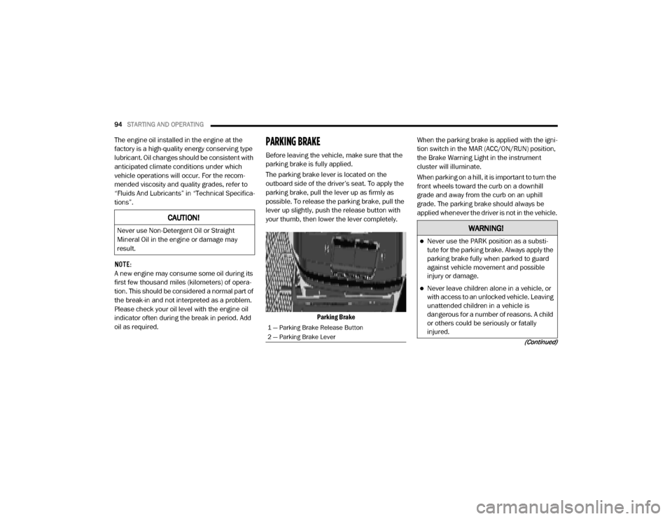
The parking brake lever is located on the
outboard side of the driver’s seat. To apply the
parking brake, pull the lever up as firmly as
possible. To release the parking brake, pull the
lever up slightly, push the release button with
your thumb, then lower the lever completely.
Parking Brake When the parking brake is applied with the igni
-
tion switch in the MAR (ACC/ON/RUN) position,
the Brake Warning Light in the instrument
cluster will illuminate.
When parking on a hill, it is important to turn the
front wheels toward the curb on a downhill
grade and away from the curb on an uphill
grade. The parking brake should always be
applied whenever the driver is not in the vehicle.
CAUTION!
Never use Non-Detergent Oil or Straight
Mineral Oil in the engine or damage may
result.
1 — Parking Brake Release Button
2 — Parking Brake Lever
WARNING!
Never use the PARK position as a substi -
tute for the parking brake. Always apply the
parking brake fully when parked to guard
against vehicle movement and possible
injury or damage.
Never leave children alone in a vehicle, or
with access to an unlocked vehicle. Leaving
unattended children in a vehicle is
dangerous for a number of reasons. A child
or others could be seriously or fatally
injured.
20_VF_OM_EN_US_t.book Page 94
Page 99 of 264
STARTING AND OPERATING97
(Continued)
Only shift from DRIVE to PARK or REVERSE
when the accelerator pedal is released and the
vehicle is stopped. Be sure to keep your foot on
the brake pedal when shifting between these
gears.
The transmission gear selector provides PARK,
REVERSE, NEUTRAL, DRIVE, and Electronic
Range Select (ERS) shift positions. Manual
downshifts can be made using the ERS shift
control. Moving the gear selector into the ERS
(-/+) position (beside the DRIVE position) acti -
vates ERS mode, displays the current gear in
the instrument cluster, and prevents automatic
upshifts beyond this gear. In ERS mode,
toggling the gear selector forward (-) or rear -
ward (+) will change the highest available gear.
Refer to "Electronic Range Select (ERS) Opera -
tion" in this section for further information.
NOTE:
If the gear selector cannot be moved to the
PARK, REVERSE, or NEUTRAL position (when
pushed forward) it is probably in the ERS (+/-)
position (beside the DRIVE position). In ERS
mode, the transmission gear limit (1, 2, 3, etc.)
is displayed in the instrument cluster. Move the gear selector to the right (into the DRIVE [D]
position) for access to PARK, REVERSE, and
NEUTRAL.
Gear Ranges
Do not depress the accelerator pedal when
shifting from PARK or NEUTRAL into another
gear range.
NOTE:
After selecting any gear range, wait a moment
to allow the selected gear to engage before
accelerating. This is especially important when
the engine is cold.
PARK (P)
This range supplements the parking brake by
locking the transmission. The engine can be
started in this range. Never attempt to use
PARK while the vehicle is in motion. Apply the
parking brake when exiting the vehicle in this
range.
When parking on a level surface, you may shift
the transmission into PARK first, and then apply
the parking brake. When parking on a hill, apply the parking brake
before shifting the transmission to PARK, other
-
wise the load on the transmission locking mech -
anism may make it difficult to move the gear
selector out of PARK. As an added precaution,
turn the front wheels toward the curb on a
downhill grade, and away from the curb on an
uphill grade.
When exiting the vehicle, always:
Apply the parking brake.
Shift the transmission into PARK.
Turn the engine OFF.
Remove the ignition key.
WARNING!
Never use the PARK position as a substi -
tute for the parking brake. Always apply the
parking brake fully when exiting the vehicle
to guard against vehicle movement and
possible injury or damage.
5
20_VF_OM_EN_US_t.book Page 97
Page 102 of 264
100STARTING AND OPERATING
Transmission Limp Home Mode
Transmission function is monitored electroni -
cally for abnormal conditions. If a condition is
detected that could result in transmission
damage, Transmission Limp Home Mode is acti -
vated. In this mode, the transmission remains
in third gear regardless of which forward gear is
selected. PARK, REVERSE, and NEUTRAL will
continue to operate. The Malfunction Indicator
Light (MIL) may be illuminated. Transmission
Limp Home Mode allows the vehicle to be
driven to an authorized dealer for service
without damaging the transmission. In the event of a momentary problem, the trans
-
mission can be reset to regain all forward gears
by performing the following steps:
1. Stop the vehicle.
2. Shift the transmission into PARK.
3. Turn the ignition OFF.
4. Wait approximately 10 seconds.
5. Restart the engine.
6. Shift into the desired gear range. If the problem is no longer detected, the trans -
mission will return to normal operation.
NOTE:
Even if the transmission can be reset, we
recommend that you visit your authorized
dealer at your earliest possible convenience.
Your authorized dealer has diagnostic equip -
ment to assess the condition of your transmis -
sion.
If the transmission cannot be reset, authorized
dealer service is required.
Electronic Range Select (ERS) Operation
The Electronic Range Select (ERS) shift control
allows the driver to limit the highest available
gear. For example, if you set the transmission
gear limit to 4 (fourth gear), the transmission
will not shift above fourth gear, but will shift
through the lower gears normally.
You can switch between DRIVE and ERS mode
at any vehicle speed. When the gear selector is
in the DRIVE position, the transmission will
operate automatically, shifting between all
available gears. Moving the gear selector to the
ERS position (beside DRIVE) will activate ERS
mode, display the current gear in the instru -
ment cluster, and set that gear as the top avail -
able gear. Once in ERS mode, moving the gear
selector forward (-) or rearward (+) will change
the top available gear.
To exit ERS mode, simply return the gear
selector to the DRIVE position.
WARNING!
Do not downshift for additional engine
braking on a slippery surface. The drive
wheels could lose their grip and the vehicle
could skid, causing a collision or personal
injury.
20_VF_OM_EN_US_t.book Page 100