tow Ram ProMaster 2020 Owner's Manual
[x] Cancel search | Manufacturer: RAM, Model Year: 2020, Model line: ProMaster, Model: Ram ProMaster 2020Pages: 264, PDF Size: 10.11 MB
Page 6 of 264

4
VEHICLE LOADING ................................................112
Vehicle Certification Label ............................... 112
Gross Vehicle Weight Rating (GVWR) .............. 112
Gross Axle Weight Rating (GAWR) .................. 112
Tire Size .............................................................112
Rim Size ............................................................ 112
Inflation Pressure ............................................. 112
Curb Weight ...................................................... 112
Overloading ....................................................... 112
Loading .............................................................113
TRAILER TOWING ..................................................113
Common Towing Definitions ............................113
Trailer Hitch Classification ............................... 114
Trailer Towing Weights
(Maximum Trailer Weight Ratings) ................. 115 Trailer And Tongue Weight ..............................115Towing Requirements ..................................... 116
Towing Tips ...................................................... 118
RECREATIONAL TOWING
(BEHIND MOTORHOME, ETC.) ............................120
Towing This Vehicle Behind Another Vehicle .. 120
Recreational Towing ......................................... 120
DRIVING TIPS.........................................................121
Driving On Slippery Surfaces ..........................121
Driving Through Water ....................................121
IN CASE OF EMERGENCY
HAZARD WARNING FLASHERS ..........................123 BULB REPLACEMENT ........................................... 123
Replacement Bulbs .......................................... 123
Replacing Exterior Bulbs .................................. 125
Replacing Interior Bulbs .................................. 127
FUSES..................................................................... 128
Underhood Fuses ............................................. 128
Interior Fuses.................................................... 131
Right Central Pillar Fuses ................................ 132
JACKING AND TIRE CHANGING .......................... 133
Jack Location .................................................... 133
Spare Tire Removal .......................................... 134
Preparations For Jacking ................................. 135
Jacking Instructions ......................................... 136Wheel Covers .................................................... 139
TIRE SERVICE KIT — IF EQUIPPED ...................... 139
Tire Service Kit Storage ................................... 139
Tire Service Kit Components And Operation .. 140Tire Service Kit Usage Precautions ................. 140
Sealing A Tire With Tire Service Kit ................. 142
JUMP STARTING ................................................... 145
Preparations For Jump Start ........................... 145
Jump Starting Procedure ................................. 146
Battery Location ............................................... 147
IF YOUR ENGINE OVERHEATS ............................ 147
GEAR SELECTOR OVERRIDE .............................. 148FREEING A STUCK VEHICLE ............................... 149
TOWING A DISABLED VEHICLE........................... 149
Automatic Transmission .................................. 150
ENHANCED ACCIDENT RESPONSE SYSTEM
(EARS) ....................................................................151
EVENT DATA RECORDER (EDR) .......................... 151
SERVICING AND MAINTENANCE
SCHEDULED SERVICING .....................................152
Maintenance Plan ............................................ 152
Heavy Duty Use Of The Vehicle ....................... 155
ENGINE COMPARTMENT...................................... 156
3.6L Engine ..................................................... 156
Checking Oil Level — Gas Engine ................... 157
Adding Washer Fluid ........................................ 157Maintenance-Free Battery .............................. 157
Pressure Washing ............................................ 158
DEALER SERVICE ................................................. 158
Engine Oil ......................................................... 158Engine Oil Filter ................................................ 159
Engine Air Cleaner Filter ................................. 159
Air Conditioner Maintenance ......................... 160
Body Lubrication .............................................. 161
Windshield Wiper Blades ................................ 162
Exhaust System ............................................... 162
Cooling System................................................. 163
Brake System .................................................. 166
Automatic Transmission
(3.6L Gasoline Engine Only) ............................ 167
RAISING THE VEHICLE..........................................168
20_VF_OM_EN_US_t.book Page 4
Page 20 of 264
18GETTING TO KNOW YOUR VEHICLE
Swivel Seat — If Equipped
The swivel seat lever is located at the lower
front inboard side of the seat. The seat may be
turned through 180° toward the seat on the
opposite side and approximately 35° toward
the door. The seat may be locked in the driving
position or at the 180° position. To swivel the
seat, pull the swivel seat inboard lever outward,
turn the seat to the desired position and release
the lever.
Swivel Seat Lever
If the vehicle is equipped with interlocking
swivel seats, the seats must be locked in the
facing forward position while driving. If the seats
are not in the correct position, a warning will
appear in the instrument cluster display. If the driver or the passenger seats are not
locked in the facing forward position before the
first vehicle movement, shifting out of park is
not allowed until the seats are both locked in
the facing forward position. When the seats are
not in the right position and the first vehicle
movement after ignition START is attempted, a
chime and a message will appear in the instru
-
ment cluster display. Rotate and lock the swivel
seats in the correct position before trying again.
If the driver or the passenger seats are not
locked in the facing forward position during
movement of the vehicle, a message will appear
in the instrument cluster display and an inter -
mittent chime will sound until key-off or until the
swivel seats are locked in the facing forward
position. Stop and move the swivel seats in the
correct position before proceeding.
If a fault is present in the system and it is not
possible to check the correct position of the
swivel seats, a message and the generic
warning light appears in the instrument cluster
display to inform about the failure. In these
conditions, check the status of the swivel seats
and do not drive the vehicle until the swivel
seats are locked in the facing forward position.
Heated Seats — If Equipped
On some models, the front driver and
passenger seats may be equipped with heaters
in both the seat cushions and seatbacks. The
controls for the front heated seats are located
on the lower outboard side of the seat.
Heated Seat Switch
Push the switch once to turn on the heated
seats. Push the switch a second time to shut the
heating elements off.
NOTE:
Once a heat setting is selected, heat will be felt
within two to five minutes.
20_VF_OM_EN_US_t.book Page 18
Page 22 of 264
20GETTING TO KNOW YOUR VEHICLE
HEAD RESTRAINTS
Head restraints are designed to reduce the risk
of injury by restricting head movement in the
event of a rear impact. Head restraints should
be adjusted so that the top of the head restraint
is located above the top of your ear.
Front Head Restraint Adjustment
To raise the head restraint, pull upward on the
head restraint. To lower the head restraint,
push the adjustment button located on the
base of the head restraint and push downward
on the head restraint.
Adjustment Buttons
NOTE:
Do not reposition the head restraint 180
degrees to the incorrect position in an attempt
to gain additional clearance to the back of the
head.
Front Head Restraint Removal
To remove the head restraint, raise it up as far
as it can go. Then, push the adjustment button
and the release button at the base of each post
while pulling the head restraint up. To reinstall
the head restraint, put the head restraint posts
into the holes. Then, adjust it to the appropriate
height.
NOTE:
Do not reposition the head restraint 180
degrees to the incorrect position in an attempt
to gain additional clearance to the back of the
head.
WARNING!
All occupants, including the driver, should
not operate a vehicle or sit in a vehicle’s
seat until the head restraints are placed in
their proper positions in order to minimize
the risk of neck injury in the event of a
crash.
Head restraints should never be adjusted
while the vehicle is in motion. Driving a
vehicle with the head restraints improperly
adjusted or removed could cause serious
injury or death in the event of a collision.
1 — Release Button
2 — Adjustment Button
WARNING!
A loose head restraint thrown forward in a
collision or hard stop could cause serious
injury or death to occupants of the vehicle.
Always securely stow removed head
restraints in a location outside the occu -
pant compartment.
ALL the head restraints MUST be rein -
stalled in the vehicle to properly protect the
occupants. Follow the re-installation
instructions above prior to operating the
vehicle or occupying a seat.
20_VF_OM_EN_US_t.book Page 20
Page 23 of 264
GETTING TO KNOW YOUR VEHICLE21
STEERING WHEEL
Telescoping Steering Column
This feature allows you to lengthen or shorten
the steering column. The telescoping control
handle is located below the steering wheel at
the end of the steering column.
Telescoping Control Handle
To unlock the steering column, pull the control
handle up. To lengthen or shorten the steering
column, pull the steering wheel outward or push
it inward as desired. To lock the steering column
in position, push the control handle down until
fully engaged.
MIRRORS
Inside Day/Night Mirror — If Equipped
A two-point pivot system allows for horizontal
and vertical adjustment of the mirror. Adjust the
mirror to center on the view through the rear
window.
Headlight glare can be reduced by moving the
small control under the mirror to the night posi -
tion (toward the rear of the vehicle). The mirror
should be adjusted while set in the day position
(toward the windshield). Adjusting Rearview Mirror
Outside Mirrors
To receive maximum benefit, adjust the outside
mirror(s) to center on the adjacent lane of traffic
with a slight overlap of the view obtained on the
inside mirror.
WARNING!
Do not adjust the steering column while
driving. Adjusting the steering column while
driving or driving with the steering column
unlocked, could cause the driver to lose
control of the vehicle. Failure to follow this
warning may result in serious injury or death.
WARNING!
Vehicles and other objects seen in an outside
convex mirror will look smaller and farther
away than they really are. Relying too much
on side convex mirrors could cause you to
collide with another vehicle or other object.
Use your inside mirror when judging the size
or distance of a vehicle seen in a side convex
mirror.
2
20_VF_OM_EN_US_t.book Page 21
Page 24 of 264
22GETTING TO KNOW YOUR VEHICLE
Outside Mirrors Folding Feature
All outside mirrors are hinged and may be
moved either forward or rearward to resist
damage. The hinges have three detent posi -
tions:
Full forward position
Full rearward position
Normal position
Power Mirrors — If Equipped
The power mirror controls are located on the
driver-side door trim panel.
Power Mirror Controls To adjust a mirror, turn the control knob toward
the left upper, left lower, right upper or right
lower mirror positions indicated by one of the
four arrows on the switch. Tilt the control wand
in the direction you want the mirror to move.
When you are finished adjusting the mirror, turn
the control to the center position “O” to prevent
accidentally moving a mirror.
NOTE:
If your vehicle is equipped with a power blind
spot mirror, you can adjust them when the
control wand is positioned to the lower arrows.
Power Folding Mirrors — If Equipped
The switch for the power folding mirrors is
located on the driver’s door panel below the
power mirror controls.
Power Folding Mirror Switch Location Push the switch to the right and the mirrors will
fold in, push the switch to the left and the
mirrors will return to the normal driving position.
Power Folding Mirror Switch
The power folding mirrors are designed to be
folded and unfolded using the power folding
switch. If the mirrors are manually folded, the
mirror head may appear loose.
If the mirror head or pivot exhibits a slight
amount of play, the mirror should be power
folded closed, then power folded open (this may
require multiple button pushes).
1 — Power Folding Mirror (Normal Driving Position)
2 — Power Folding Mirror (Fold In Position)
20_VF_OM_EN_US_t.book Page 22
Page 26 of 264
24GETTING TO KNOW YOUR VEHICLE
Daytime Running Lights (DRLs) — If
Equipped
NOTE:
When the headlights are turned on, the Daytime
Running Lights will be deactivated.
To activate the Daytime Running Lights (DRLs),
rotate the end of the multifunction lever to the
O (off) position.
NOTE:
The low beams and side/taillights will not be
on with DRLs.
In certain markets, the DRLs may be optional
and can be programmed to be on or off
through the Uconnect system screen. Refer
to “Uconnect Settings” in “Multimedia” for
further information.
The Daytime Running Lights will come on when -
ever the ignition is ON, the headlight switch is
off, and the turn signal is off.
High Beam/Low Beam Select Switch
With the low beams activated, pull the multi -
function lever toward the steering wheel to
switch the headlights to high beam. A high
beam symbol will be illuminated in the cluster to
indicate the high beams are on. Pull the lever a
second time to switch the headlights back to
low beam.
NOTE:
If the vehicle’s ignition is placed in the STOP
(OFF/LOCK) position, both high and low beam
headlights will also be turned off.
Flash-To-Pass
You can signal another vehicle with your head -
lights by partially pulling the multifunction lever
toward the steering wheel. This will cause the
high beam headlights to turn on until the lever
is released.
Parking Lights
These lights can only be turned on with ignition
key in the STOP (OFF/LOCK) position or
removed, by moving the end of the multifunc -
tion lever to O (off) position and then to the
headlight position. The warning light telltale in the instrument
panel comes on. The lights stay on until the next
ignition cycle is performed.
Follow Me Home/Headlight Delay
When this feature is selected, the driver can
choose to have the headlights remain on for a
preset period of time.
Activation
Remove the key or turn the ignition to the STOP
(OFF/LOCK) position, and pull the multifunction
lever toward the steering wheel, within two
minutes. Each time the lever is pulled, the acti
-
vation of the lights will be extended by 30
seconds. The activation of the lights can be
extended to a maximum of 210 seconds.
The warning light on the instrument panel will
light up and the corresponding message will
appear in the instrument cluster display for as
long as the function is activated. The warning
light comes on when the lever is operated and
stays on until the function is automatically deac -
tivated. Each movement of the lever only
increases the amount of time the lights stay on.
Deactivation
Pull the multifunction lever toward the steering
wheel and hold it for more than two seconds.
20_VF_OM_EN_US_t.book Page 24
Page 30 of 264
28GETTING TO KNOW YOUR VEHICLE
Intermittent Wiper System
Push the lever downward to the first detent and
rotate the center ring to use one of the four
intermittent wiper settings when weather condi -
tions make a single wiping cycle, with a variable
delay between cycles, desirable.
Low Speed
Push the lever downward to the second detent.
The wipers will operate at low speed.
High Speed
Push the lever downward to the third detent.
The wipers will operate at high speed.
Windshield Washer Operation
To use the washer, pull the windshield wiper/
washer lever toward the steering wheel to acti -
vate. The wipers will activate automatically for
three cycles after the lever is released, and then
resume the intermittent interval previously
selected.
If the lever is pulled while in the off position, the
wipers will operate for three cycles and then
turn off.
Mist Feature
Use the Mist feature when weather conditions
make occasional usage of the wipers neces -
sary. Push the lever upward to the MIST position
and release for a single wiping cycle.
NOTE:
The mist feature does not activate the washer
pump; therefore, no washer fluid will be sprayed
on the windshield. The wash function must be
used in order to spray the windshield with
washer fluid.
CLIMATE CONTROLS
The Climate Control System allows you to regu -
late the temperature, air flow, and direction of
air circulating throughout the vehicle. The
controls are located on the touchscreen (if
equipped) and on the instrument panel below
the radio.
Manual Climate Control Overview
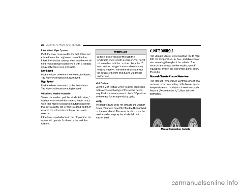
The Manual Temperature Controls consist of a
series of three outer rotary dials (blower speed,
temperature and mode) and three inner push
buttons (Recirculation, A/C, Rear Window
Defroster).
Manual Temperature Controls
WARNING!
Sudden loss of visibility through the
windshield could lead to a collision. You might
not see other vehicles or other obstacles. To
avoid sudden icing of the windshield during
freezing weather, warm the windshield with
the defroster before and during windshield
washer use.
20_VF_OM_EN_US_t.book Page 28
Page 50 of 264
48GETTING TO KNOW YOUR INSTRUMENT PANEL
Electronic Throttle Control (ETC) Warning Light
This warning light will illuminate to
inform of a problem with the Elec -
tronic Throttle Control (ETC) system. If
a problem is detected while the
vehicle is running, the light will either stay on or
flash depending on the nature of the problem.
Cycle the ignition when the vehicle is safely and
completely stopped and the transmission is
placed in the PARK (P) position. The light should
turn off. If the light remains on with the vehicle
running, your vehicle will usually be drivable;
however, see an authorized dealer for service
as soon as possible.
If the light continues to flash when the vehicle is
running, immediate service is required and you
may experience reduced performance, an
elevated/rough idle, or engine stall and your
vehicle may require towing. The light will come
on when the ignition is placed in the ON/RUN or
MAR/ON/RUN position and remain on briefly as
a bulb check. If the light does not come on
during starting, have the system checked by an
authorized dealer.
Transmission Fault Warning Light
This light will illuminate (together with
a message in the instrument cluster
display and a buzzer) to indicate a
transmission fault. Contact an autho -
rized dealer if the message remains after
restarting the engine.
Engine Temperature Warning Light
This light warns of an overheated
engine condition. If the engine
coolant temperature is too high, this
indicator will illuminate and a single
chime will sound.
If the light turns on while driving, safely pull over
and stop the vehicle. If the A/C system is on,
turn it off. Also, shift the transmission into
NEUTRAL and idle the vehicle. If the tempera -
ture reading does not return to normal, turn the
engine off immediately and call for service.
Refer to “If Your Engine Overheats” in “In Case
Of Emergency” for further information.
Brake Warning Light
This warning light monitors various
brake functions, including brake
fluid level and parking brake appli -
cation. If the brake light turns on it
may indicate that the parking brake is
applied, that the brake fluid level is low, or
that there is a problem with the anti-lock
brake system reservoir.
If the light remains on when the parking brake
has been disengaged, and the fluid level is at
the full mark on the master cylinder reservoir, it
indicates a possible brake hydraulic system
malfunction or that a problem with the Brake
Booster has been detected by the Anti-Lock
Brake System (ABS) / Electronic Stability
Control (ESC) system. In this case, the light will
remain on until the condition has been
corrected. If the problem is related to the brake
booster, the ABS pump will run when applying
the brake, and a brake pedal pulsation may be
felt during each stop.
20_VF_OM_EN_US_t.book Page 48
Page 54 of 264
52GETTING TO KNOW YOUR INSTRUMENT PANEL
Certain conditions, such as a loose or missing
gas cap, poor quality fuel, etc., may illuminate
the light after engine start. The vehicle should
be serviced if the light stays on through several
typical driving styles. In most situations, the
vehicle will drive normally and will not require
towing.
When the engine is running, the MIL may flash
to alert serious conditions that could lead to
immediate loss of power or severe catalytic
converter damage. The vehicle should be
serviced by an authorized dealer as soon as
possible if this occurs.
Anti-Lock Brake (ABS) Warning Light
This light monitors the Anti-Lock
Brake System (ABS). The light will turn
on when the ignition is placed in the
ON/RUN or MAR/ON/RUN position
and may stay on for as long as four seconds.
If the ABS light remains on or turns on while
driving, then the Anti-Lock portion of the brake
system is not functioning and service is
required. However, the conventional brake
system will continue to operate normally if the
brake warning light is not on.
If the ABS light is on, the brake system should
be serviced as soon as possible to restore the
benefits of Anti-Lock Brakes. If the ABS light
does not turn on when the ignition is placed in
the ON/RUN or MAR/ON/RUN position, have
the light inspected by an authorized dealer.
Generic Warning Light
The Generic Warning Light will illumi -
nate if any of the following conditions
occur: Engine Oil Pressure Sensor
Failure, External Light Failure, Fuel
Cut-Off intervention or fail, Parking Sensor
Failure, DST System Failure.
The telltale will remain on fixed in case of swivel
seat failure and on blinking in case of Air Bag
Warning Light Failure. Contact an authorized
dealer immediately for service.
Yellow Indicator Lights
Stop Light Failure Indicator Light
This light will illuminate if one or more
of the stop light bulb fails.
The failure relating to this light could be:
One or more blown bulbs.
A blown protection fuse.
A break in the electrical connection.
WARNING!
A malfunctioning catalytic converter, as
referenced above, can reach higher
temperatures than in normal operating
conditions. This can cause a fire if you drive
slowly or park over flammable substances
such as dry plants, wood, cardboard, etc. This
could result in death or serious injury to the
driver, occupants or others.
CAUTION!
Prolonged driving with the Malfunction
Indicator Light (MIL) on could cause damage
to the vehicle control system. It also could
affect fuel economy and driveability. If the
MIL is flashing, severe catalytic converter
damage and power loss will soon occur.
Immediate service is required.
20_VF_OM_EN_US_t.book Page 52
Page 55 of 264
GETTING TO KNOW YOUR INSTRUMENT PANEL53
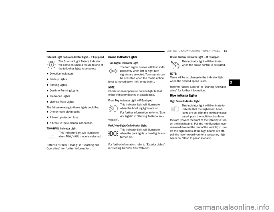
External Light Failure Indicator Light — If Equipped
The External Light Failure Indicator
will come on when a failure to one of
the following lights is detected:
Direction Indicators
Backup Lights
Parking Lights
Daytime Running Lights
Clearance Lights
License Plate Lights
The failure relating to these lights could be:
One or more blown bulbs
A blown protection fuse
A break in the electrical connection
TOW/HAUL Indicator Light
This indicator light will illuminate
when TOW/HAUL mode is selected.
Refer to “Trailer To wing ” in “Starting And
Operating” for further information.
Green Indicator Lights
Turn Signal Indicator Light
The turn signal arrows will flash inde -
pendently when left or right turn
signals are selected. Turn signals can
be activated when the multifunction
lever is moved down (left) or up (right).
NOTE:
Check for an inoperative outside light bulb if
either indicator flashes at a rapid rate.
Front Fog Indicator Light — If Equipped
This indicator light will illuminate
when the front fog lights are on.
For further information, refer to “Exte -
rior Lights” in “Getting To Know Your
Vehicle”.
Park/Headlight On Indicator Light
This indicator light will illuminate
when the park lights or headlights are
turned on.
For further information, refer to “Exterior Lights”
in “Getting To Know Your Vehicle”.
Cruise Control Indicator Light — If Equipped
This indicator light will illuminate
when the cruise control is activated.
NOTE:
There will be no change in the indicator light
when the desired speed is set.
Refer to “Speed Control” in “Starting And Oper -
ating” for further information.
Blue Indicator Lights
High Beam Indicator Light
This indicator light will illuminate to
indicate that the high beam head -
lights are on. With the low beams acti -
vated, push the multifunction lever
forward (toward the front of the vehicle) to turn
on the high beams. Pull the multifunction lever
rearward (toward the rear of the vehicle) to turn
off the high beams. If the high beams are off,
pull the lever toward you for a temporary high
beam on, “flash to pass” scenario.
3
20_VF_OM_EN_US_t.book Page 53