engine Ram ProMaster 2020 Owner's Manual
[x] Cancel search | Manufacturer: RAM, Model Year: 2020, Model line: ProMaster, Model: Ram ProMaster 2020Pages: 264, PDF Size: 10.11 MB
Page 2 of 264
WARNING: Operating, servicing and maintaining a passenger vehicle or off-highway
motor vehicle can expose you to chemicals including engine exhaust, carbon monoxide,
phthalates, and lead, which are known to the State of California to cause cancer and birth defects
or other reproductive harm. To minimize exposure, avoid breathing exhaust, do not idle the
engine except as necessary, service your vehicle in a well-ventilated area and wear gloves or wash
your hands frequently when servicing your vehicle. For more information go to
www.P65Warnings.ca.gov/passenger-vehicle.
This Owner’s Manual illustrates and describes the operation of features and equipment that are either standard or optional on this vehicle. This manual may
also include a description of features and equipment that are no longer available or were not ordered on this vehicle. Please disregard any features and
equipment that are no longer available or were not ordered on this vehicle. FCA US LLC reserves the right to make changes in design and specifications, and/or make additions to or improvements to its products without imposing any obligation upon itself to install them on products previously manufactured.
With respect to vehicles sold in Canada, the name FCA US LLC shall be deemed to be deleted and the name FCA Canada Inc. used in substitution therefore.
If you are the first registered retail owner of your vehicle, you may obtain a complimentary printed copy of the Warranty Booklet by calling
1-866-726-4636 (U.S.) or 1-800-387-1143 (Canada), or by contacting your dealer.
This Owner’s Manual is intended to familiarize you with the important features of your vehicle. Your most up-to-date Owner’s Manual, Navigation/Uconnect manuals and Warranty Booklet can be found by visiting the website on the back cover. U.S. residents can purchase replacement kits by visiting www.techauthority.com and Canadian residents can purchase replacement kits by calling 1-800-387-1143.
Page 5 of 264

3
GETTING TO KNOW YOUR INSTRUMENT
PANEL
INSTRUMENT CLUSTER .......................................... 41
Instrument Cluster Descriptions........................ 42
INSTRUMENT CLUSTER DISPLAY ......................... 43
Location And Controls ........................................ 43
Change Engine Oil .............................................. 44
Display Setup Menu ........................................... 44
Values Displayed ................................................ 45
Personal Settings (Customer-Programmable
Features) ............................................................. 46
TRIP COMPUTER ..................................................... 46
Trip Button .......................................................... 46
Trip Functions ..................................................... 46
WARNING LIGHTS AND MESSAGES ..................... 47
Red Warning Lights ............................................ 47
Yellow Warning Lights ........................................ 50
Yellow Indicator Lights ....................................... 52
Green Indicator Lights ........................................ 53
Blue Indicator Lights .......................................... 53
ONBOARD DIAGNOSTIC SYSTEM — OBD II ........ 54
Onboard Diagnostic System (OBD II)
Cybersecurity ...................................................... 54
EMISSIONS INSPECTION AND MAINTENANCE
PROGRAMS ............................................................. 55
SAFETY
SAFETY FEATURES ..................................................56
Four-Wheel Anti-Lock Brake System (ABS) ....... 56
Electronic Brake Control (EBC) System ........... 57
AUXILIARY DRIVING SYSTEMS ..............................61
Tire Pressure Monitoring System (TPMS) ......... 61
OCCUPANT RESTRAINT SYSTEMS .......................64
Occupant Restraint Systems Features ............ 64
Important Safety Precautions............................ 65
Seat Belt Systems ............................................. 66
Supplemental Restraint Systems (SRS) ........... 73
Child Restraints .................................................. 83
Transporting Pets .............................................. 89
SAFETY TIPS ............................................................89
Transporting Passengers ................................... 89
Exhaust Gas ........................................................ 89
Safety Checks You Should Make Inside
The Vehicle ........................................................ 90 Periodic Safety Checks You Should Make
Outside The Vehicle ........................................... 91
STARTING AND OPERATING
STARTING THE ENGINE ..........................................92
Automatic Transmission .................................... 92
Normal Starting .................................................. 92
Cold Weather Operation
(Below –22°F Or −30°C) ................................. 92 If Engine Fails To Start ....................................... 92
After Starting ...................................................... 93
ENGINE BLOCK HEATER — IF EQUIPPED ............ 93
ENGINE BREAK-IN RECOMMENDATIONS ........... 93
PARKING BRAKE ................................................... 94
AUTOMATIC TRANSMISSION ................................ 95
Key Ignition Park Interlock .................................96
Brake/Transmission Shift Interlock System ....96
Six-Speed Automatic Transmission ...................96
POWER STEERING ............................................... 102
Power Steering Fluid Check ........................... 103
SPEED CONTROL — IF EQUIPPED ......................103
To Activate ........................................................ 103
To Set A Desired Speed ................................... 104
To Vary The Speed Setting .............................. 104
To Accelerate For Passing ............................... 105
To Resume Speed ............................................ 105
To Deactivate ................................................... 105
PARKSENSE REAR PARK ASSIST —
IF EQUIPPED ..........................................................105
ParkSense Rear Park Assist Sensors ............. 106
ParkSense Rear Park Assist Alerts ................. 106
ParkSense Rear Park Assist Failure
Indications ........................................................ 108 Cleaning The ParkSense System .................... 108
ParkSense Rear Park Assist System Usage
Precautions ...................................................... 108
PARKVIEW REAR BACK UP CAMERA ............... 109
REFUELING THE VEHICLE.....................................111
Loose Fuel Filler Cap Message ....................... 111
20_VF_OM_EN_US_t.book Page 3
Page 6 of 264

4
VEHICLE LOADING ................................................112
Vehicle Certification Label ............................... 112
Gross Vehicle Weight Rating (GVWR) .............. 112
Gross Axle Weight Rating (GAWR) .................. 112
Tire Size .............................................................112
Rim Size ............................................................ 112
Inflation Pressure ............................................. 112
Curb Weight ...................................................... 112
Overloading ....................................................... 112
Loading .............................................................113
TRAILER TOWING ..................................................113
Common Towing Definitions ............................113
Trailer Hitch Classification ............................... 114
Trailer Towing Weights
(Maximum Trailer Weight Ratings) ................. 115 Trailer And Tongue Weight ..............................115Towing Requirements ..................................... 116
Towing Tips ...................................................... 118
RECREATIONAL TOWING
(BEHIND MOTORHOME, ETC.) ............................120
Towing This Vehicle Behind Another Vehicle .. 120
Recreational Towing ......................................... 120
DRIVING TIPS.........................................................121
Driving On Slippery Surfaces ..........................121
Driving Through Water ....................................121
IN CASE OF EMERGENCY
HAZARD WARNING FLASHERS ..........................123 BULB REPLACEMENT ........................................... 123
Replacement Bulbs .......................................... 123
Replacing Exterior Bulbs .................................. 125
Replacing Interior Bulbs .................................. 127
FUSES..................................................................... 128
Underhood Fuses ............................................. 128
Interior Fuses.................................................... 131
Right Central Pillar Fuses ................................ 132
JACKING AND TIRE CHANGING .......................... 133
Jack Location .................................................... 133
Spare Tire Removal .......................................... 134
Preparations For Jacking ................................. 135
Jacking Instructions ......................................... 136Wheel Covers .................................................... 139
TIRE SERVICE KIT — IF EQUIPPED ...................... 139
Tire Service Kit Storage ................................... 139
Tire Service Kit Components And Operation .. 140Tire Service Kit Usage Precautions ................. 140
Sealing A Tire With Tire Service Kit ................. 142
JUMP STARTING ................................................... 145
Preparations For Jump Start ........................... 145
Jump Starting Procedure ................................. 146
Battery Location ............................................... 147
IF YOUR ENGINE OVERHEATS ............................ 147
GEAR SELECTOR OVERRIDE .............................. 148FREEING A STUCK VEHICLE ............................... 149
TOWING A DISABLED VEHICLE........................... 149
Automatic Transmission .................................. 150
ENHANCED ACCIDENT RESPONSE SYSTEM
(EARS) ....................................................................151
EVENT DATA RECORDER (EDR) .......................... 151
SERVICING AND MAINTENANCE
SCHEDULED SERVICING .....................................152
Maintenance Plan ............................................ 152
Heavy Duty Use Of The Vehicle ....................... 155
ENGINE COMPARTMENT...................................... 156
3.6L Engine ..................................................... 156
Checking Oil Level — Gas Engine ................... 157
Adding Washer Fluid ........................................ 157Maintenance-Free Battery .............................. 157
Pressure Washing ............................................ 158
DEALER SERVICE ................................................. 158
Engine Oil ......................................................... 158Engine Oil Filter ................................................ 159
Engine Air Cleaner Filter ................................. 159
Air Conditioner Maintenance ......................... 160
Body Lubrication .............................................. 161
Windshield Wiper Blades ................................ 162
Exhaust System ............................................... 162
Cooling System................................................. 163
Brake System .................................................. 166
Automatic Transmission
(3.6L Gasoline Engine Only) ............................ 167
RAISING THE VEHICLE..........................................168
20_VF_OM_EN_US_t.book Page 4
Page 7 of 264

5
TIRES .....................................................................168
Tire Safety Information ....................................168
Tires — General Information ........................... 176
Tire Types .......................................................... 180
Spare Tires — If Equipped ............................... 181
Wheel And Wheel Trim Care ........................... 183
Tire Chains And Traction Devices ................... 184
Tire Rotation Recommendations..................... 185
DEPARTMENT OF TRANSPORTATION
UNIFORM TIRE QUALITY GRADES .....................185
Treadwear .........................................................186
Traction Grades ................................................ 186
Temperature Grades ........................................186
STORING THE VEHICLE ........................................186
BODYWORK ...........................................................187
Protection From Atmospheric Agents.............. 187
Body And Underbody Maintenance ................. 187
Preserving The Bodywork................................. 187
INTERIORS ............................................................188
Seats And Fabric Parts ..................................... 188
Plastic And Coated Parts..................................189
Leather Parts .................................................... 190Glass Surfaces ................................................. 190
Cleaning The Instrument Panel Cupholders ...190
TECHNICAL SPECIFICATIONS
IDENTIFICATION DATA ......................................... 191
Vehicle Identification Number ........................ 191
BRAKE SYSTEM .................................................... 191
WHEEL AND TIRE TORQUE SPECIFICATIONS ... 191
Torque Specifications ...................................... 191
FUEL REQUIREMENTS.......................................... 192
3.6L Engine....................................................... 192
Reformulated Gasoline ................................... 192
Materials Added To Fuel .................................. 193
Gasoline/Oxygenate Blends ............................ 193
Do Not Use E-85 In Non-Flex Fuel Vehicles .... 193
CNG And LP Fuel System Modifications ......... 193
MMT In Gasoline .............................................. 194Fuel System Cautions ...................................... 194
Carbon Monoxide Warnings ............................ 194
FLUID CAPACITIES................................................ 195
FLUIDS AND LUBRICANTS .................................. 195
Engine ............................................................... 195Chassis ............................................................. 197
MULTIMEDIA
CYBERSECURITY .................................................. 198
UCONNECT SETTINGS ......................................... 199
Uconnect 3/3 NAV Settings............................. 199
SAFETY AND GENERAL INFORMATION ............. 208
Safety Guidelines ............................................. 208
UCONNECT 3/3 NAV WITH 5-INCH DISPLAY ....209
Introduction To The Uconnect 3/3 NAV
With 5-Inch Display System ............................. 209 Radio Mode ...................................................... 211
Media Mode ..................................................... 214
Phone Mode ..................................................... 216
Navigation Mode — If Equipped ...................... 221
STEERING WHEEL AUDIO CONTROLS ............... 238
Radio Operation ............................................... 238
Player Operation............................................... 238
IPOD®/USB/MP3 CONTROL —
IF EQUIPPED ......................................................... 238
USB Charging Port............................................ 239
RAM TELEMATICS - IF EQUIPPED ....................... 239
Ram Telematics General Information............. 239
RADIO OPERATION AND MOBILE PHONES ......240
Regulatory And Safety Information ................. 240
UCONNECT VOICE RECOGNITION ......................241
Introducing Uconnect....................................... 241
Get Started ....................................................... 241
Basic Voice Commands ................................... 242
Radio ................................................................. 242
Media ................................................................ 243
Phone................................................................ 243
Voice Text Reply ............................................... 244
General Information......................................... 245
Additional Information ..................................... 245
20_VF_OM_EN_US_t.book Page 5
Page 9 of 264
7
INTRODUCTION
INTRODUCTION
Dear Customer,
Congratulations on selecting your new vehicle.
Be assured that it represents precision work-
manship, distinctive styling, and high quality.
This Owner’s Manual has been prepared with
the assistance of service and engineering
specialists to acquaint you with the operation
and maintenance of your vehicle. It is supple -
mented by Warranty Information and customer
oriented documents available online. Within
this information, you will find a description of
the services that FCA US LLC offers to its
customers, the vehicle's warranty coverage,
and the details of the terms and conditions for
maintaining its validity. Please take the time to
read all of these publications carefully before driving your vehicle for the first time. Following
the instructions, recommendations, tips, and
important warnings in this manual will help
assure safe and enjoyable operation of your
vehicle. Be sure you are familiar with all vehicle
controls, particularly those used for braking,
steering, transmission, and transfer case
shifting (if equipped). Learn how your vehicle
handles on different road surfaces. Your driving
skills will improve with experience.
This Owner’s Manual describes all versions of
this vehicle. Options and equipment dedicated
to specific markets or versions are not expressly
indicated in the text. Therefore, you should only
consider the information which is related to the
trim level, engine, and version that you have
purchased. Any content introduced throughout
the Owner’s Information, that may or may not be
applicable to your vehicle, will be identified with the wording “If Equipped”. All data contained in
this publication are intended to help you use
your vehicle in the best possible way. FCA US
LLC aims at a constant improvement of the
vehicles produced. For this reason, it reserves
the right to make changes to the model
described for technical and/or commercial
reasons. For further information, contact an
authorized dealer.
When it comes to service, remember that an
authorized dealer knows your vehicle best, has
factory-trained technicians and genuine
MOPAR® parts, and cares about your satisfac
-
tion.
1
20_VF_OM_EN_US_t.book Page 7
Page 14 of 264

12GETTING TO KNOW YOUR VEHICLE
Key-In-Ignition Reminder
Opening the driver's door when the key is in the
ignition and the ignition switch position is STOP
(OFF/LOCK) sounds a signal to remove the key.
SENTRY KEY
The Sentry Key Immobilizer System prevents
unauthorized vehicle operation by disabling the
engine. The system does not need to be armed
or activated. Operation is automatic, regardless
of whether the vehicle is locked or unlocked.
The system uses ignition keys which have an
embedded electronic chip (transponder) to
prevent unauthorized vehicle operation. There -
fore, only keys that are programmed to the
vehicle can be used to start and operate the
vehicle. NOTE:
A key which has not been programmed is also
considered an invalid key, even if it is cut to fit
the ignition switch lock cylinder for that vehicle.
If the vehicle security light is on after the key is
turned to the MAR (ACC/ON/RUN) position, it
indicates that there is a problem with the elec
-
tronics.
All of the keys provided with your new vehicle
have been programmed to the vehicle elec -
tronics.
Replacement Keys
NOTE:
Only keys that have been programmed to the
vehicle electronics can be used to start the
vehicle. Once a Sentry Key has been
programmed to a vehicle, it cannot be
programmed to any other vehicle. When having
the Sentry Key Immobilizer System serviced,
bring all vehicle keys with you to an authorized
dealer.
The VIN is required for authorized dealer
replacement of keys. Duplication of keys may
be performed at an authorized dealer.
General Information
The following regulatory statement applies to all
Radio Frequency (RF) devices equipped in this
vehicle:
CAUTION!
An unlocked vehicle is an invitation. Always
remove the key from the ignition and lock all
the doors when leaving the vehicle
unattended.
CAUTION!
Always remove the Sentry Key from the
vehicle and lock all doors when leaving the
vehicle unattended.
The Sentry Key Immobilizer system is not
compatible with some aftermarket remote
starting systems. Use of these systems may
result in vehicle starting problems and loss
of security protection.
20_VF_OM_EN_US_t.book Page 12
Page 35 of 264

GETTING TO KNOW YOUR VEHICLE33
Climate Control Functions
A/C (Air Conditioning)
The Air Conditioning (A/C) button allows the
operator to manually activate or deactivate the
air conditioning system. When the air condi -
tioning system is turned on, cool dehumidified
air will flow through the outlets into the cabin.
For improved fuel economy, press the A/C
button to turn off the air conditioning and manu -
ally adjust the blower and airflow mode settings.
Also, make sure to select only Panel, Bi-Level or
Floor modes.
NOTE:
For Manual Climate Controls, if the system is
in Mix, Floor or Defrost Mode, the A/C can be
turned off, but the A/C system shall remain
active to prevent fogging of the windows.
If fog or mist appears on the windshield or
side glass, select Defrost mode, and increase
blower speed if needed.
If your air conditioning performance seems
lower than expected, check the front of the
A/C condenser (located in front of the radi -
ator), for an accumulation of dirt or insects.
Clean with a gentle water spray from the front
of the radiator and through the condenser.
Recirculation
In cold weather, use of Recirculation mode may
lead to excessive window fogging. The Recircu -
lation feature may be unavailable if conditions
exist that could create fogging on the inside of
the windshield. On systems with Manual
Climate Controls, the Recirculation mode is not
allowed in Defrost mode to improve window
clearing operation. Recirculation is disabled
automatically if this mode is selected.
Attempting to use Recirculation while in this
mode causes the LED in the control button to
blink and then turns off.
Operating Tips
NOTE:
Refer to the chart at the end of this section for
suggested control settings for various weather
conditions.
Summer Operation
The engine cooling system must be protected
with a high-quality antifreeze coolant to provide
proper corrosion protection and to protect
against engine overheating. A solution of 50%
OAT (Organic Additive Technology) coolant that
meets the requirements of FCA Material Stan -dard MS.90032 and 50% water is recom
-
mended. Refer to “Fluids And Lubricants” in
“Technical Specifications” for proper coolant
selection.
Winter Operation
Use of the air Recirculation mode during Winter
months is not recommended because it may
cause window fogging.
Vacation Storage
Any time you store your vehicle or keep it out of
service (i.e., vacation) for two weeks or more,
run the air conditioning system at idle for about
five minutes in the fresh air and high blower
setting. This will ensure adequate system lubri -
cation to minimize the possibility of compressor
damage when the system is started again.
Window Fogging
Interior fogging on the windshield can be quickly
removed by turning the mode selector to
Defrost. The Defrost/Floor mode can be used to
maintain a clear windshield and provide suffi -
cient heating. If side window fogging becomes a
problem increase blower speed. Vehicle
windows tend to fog on the inside in mild but
rainy or humid weather.
2
20_VF_OM_EN_US_t.book Page 33
Page 42 of 264
40GETTING TO KNOW YOUR VEHICLE
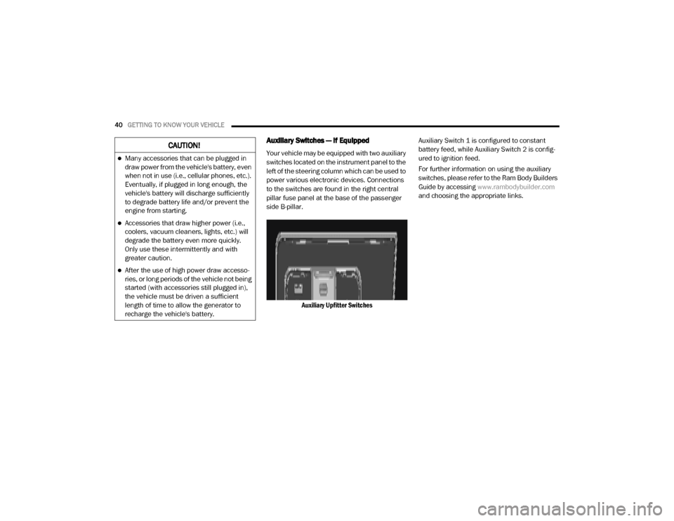
Auxiliary Switches — If Equipped
Your vehicle may be equipped with two auxiliary
switches located on the instrument panel to the
left of the steering column which can be used to
power various electronic devices. Connections
to the switches are found in the right central
pillar fuse panel at the base of the passenger
side B-pillar.
Auxiliary Upfitter Switches Auxiliary Switch 1 is configured to constant
battery feed, while Auxiliary Switch 2 is config
-
ured to ignition feed.
For further information on using the auxiliary
switches, please refer to the Ram Body Builders
Guide by accessing www.rambodybuilder.com
and choosing the appropriate links.CAUTION!
Many accessories that can be plugged in
draw power from the vehicle's battery, even
when not in use (i.e., cellular phones, etc.).
Eventually, if plugged in long enough, the
vehicle's battery will discharge sufficiently
to degrade battery life and/or prevent the
engine from starting.
Accessories that draw higher power (i.e.,
coolers, vacuum cleaners, lights, etc.) will
degrade the battery even more quickly.
Only use these intermittently and with
greater caution.
After the use of high power draw accesso -
ries, or long periods of the vehicle not being
started (with accessories still plugged in),
the vehicle must be driven a sufficient
length of time to allow the generator to
recharge the vehicle's battery.
20_VF_OM_EN_US_t.book Page 40
Page 44 of 264
42GETTING TO KNOW YOUR INSTRUMENT PANEL
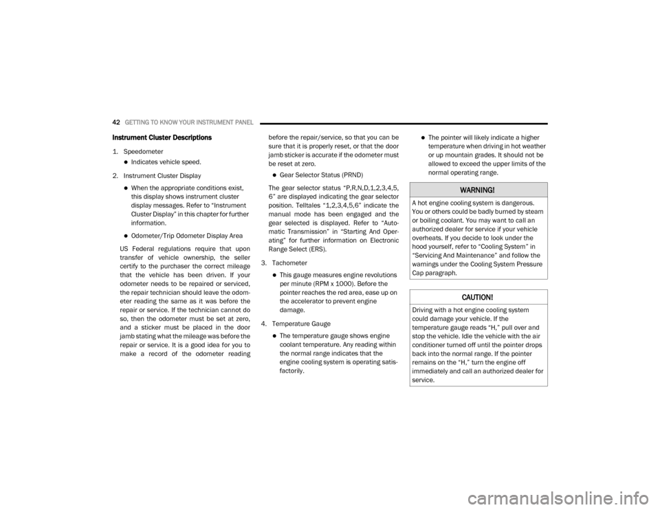
Instrument Cluster Descriptions
1. Speedometer
Indicates vehicle speed.
2. Instrument Cluster Display
When the appropriate conditions exist,
this display shows instrument cluster
display messages. Refer to “Instrument
Cluster Display” in this chapter for further
information.
Odometer/Trip Odometer Display Area
US Federal regulations require that upon
transfer of vehicle ownership, the seller
certify to the purchaser the correct mileage
that the vehicle has been driven. If your
odometer needs to be repaired or serviced,
the repair technician should leave the odom -
eter reading the same as it was before the
repair or service. If the technician cannot do
so, then the odometer must be set at zero,
and a sticker must be placed in the door
jamb stating what the mileage was before the
repair or service. It is a good idea for you to
make a record of the odometer reading before the repair/service, so that you can be
sure that it is properly reset, or that the door
jamb sticker is accurate if the odometer must
be reset at zero.
Gear Selector Status (PRND)
The gear selector status “P,R,N,D,1,2,3,4,5,
6” are displayed indicating the gear selector
position. Telltales “1,2,3,4,5,6” indicate the
manual mode has been engaged and the
gear selected is displayed. Refer to “Auto -
matic Transmission” in “Starting And Oper -
ating” for further information on Electronic
Range Select (ERS).
3. Tachometer
This gauge measures engine revolutions
per minute (RPM x 1000). Before the
pointer reaches the red area, ease up on
the accelerator to prevent engine
damage.
4. Temperature Gauge
The temperature gauge shows engine
coolant temperature. Any reading within
the normal range indicates that the
engine cooling system is operating satis-
factorily.
The pointer will likely indicate a higher
temperature when driving in hot weather
or up mountain grades. It should not be
allowed to exceed the upper limits of the
normal operating range.
WARNING!
A hot engine cooling system is dangerous.
You or others could be badly burned by steam
or boiling coolant. You may want to call an
authorized dealer for service if your vehicle
overheats. If you decide to look under the
hood yourself, refer to “Cooling System” in
“Servicing And Maintenance” and follow the
warnings under the Cooling System Pressure
Cap paragraph.
CAUTION!
Driving with a hot engine cooling system
could damage your vehicle. If the
temperature gauge reads “H,” pull over and
stop the vehicle. Idle the vehicle with the air
conditioner turned off until the pointer drops
back into the normal range. If the pointer
remains on the “H,” turn the engine off
immediately and call an authorized dealer for
service.
20_VF_OM_EN_US_t.book Page 42
Page 46 of 264
44GETTING TO KNOW YOUR INSTRUMENT PANEL
MODE Button
Push and hold the MODE button for a time
longer than one second to access/select the
information screens or submenu screens of a
main menu item. Push and hold the MODE
button for two seconds to reset displayed/
selected features that can be reset.
Up Arrow Button
Push and release the up arrow
button to scroll upward through the
main menu and submenus or
adjust the illumination on the
instrument panel when the headlights are on.
Down Arrow Button
Push and release the down arrow
button to scroll downward through
the main menu and submenus or
adjust the illumination on the
instrument panel when the headlights are on.
Change Engine Oil
Your vehicle is equipped with an engine oil
change indicator system. The “Change Engine
Oil” message will display in the instrument
cluster display. The engine oil change indicator
system is duty cycle based, which means the engine oil change interval may fluctuate, depen
-
dent upon your personal driving style.
Unless reset, this message will continue to
display each time you turn the ignition switch to
the ON/RUN position. To turn off the message
temporarily, push and release the MODE
button. To reset the oil change indicator system
(after performing the scheduled maintenance),
refer to the following procedure.
1. Turn the ignition switch to the ON position (do not start the engine).
2. Fully push the accelerator pedal slowly, three times, within 10 seconds.
3. Turn the ignition switch to the OFF/LOCK position.
NOTE:
If the indicator message illuminates when you
start the vehicle, the oil change indicator
system did not reset. If necessary, repeat this
procedure.Display Setup Menu
The menu comprises a series of functions
arranged in a cycle. Push and release the up or
down arrow button to access the different
options and settings (setup). The setup menu can be activated by pushing
the
MODE button. Single pushes on the up or
down arrow button will scroll through the setup
menu options. The menu items include the
following functions:
Speed Beep
Buzzer Volume
Seat Belt Buzzer (Just Available After SBR
Disable Made By CHR Service)
Exit menu
NOTE:
If equipped, some customer programmable
features will display in the Uconnect system.
Refer to your Uconnect Owner’s Manual Supple -
ment for further information.
Selecting An Option Of The Main Menu Without
Submenu
1. Briefly push and release the MODE button
to select the main menu option to set.
2. Push and release the up or down arrow
button (by single pushes) to select the new
setting.
20_VF_OM_EN_US_t.book Page 44