display RAM PROMASTER 2021 Owner's Manual
[x] Cancel search | Manufacturer: RAM, Model Year: 2021, Model line: PROMASTER, Model: RAM PROMASTER 2021Pages: 288, PDF Size: 15.22 MB
Page 74 of 288
72STARTING AND OPERATING
(Continued)
PARKSENSE REAR PARK ASSIST
F
AILURE INDICATIONS
A malfunction of the ParkSense Rear Park
Assist sensors or system is indicated, during
REVERSE gear engagement, by the instrument
panel warning icon.
The warning icon is illuminated and a
message is displayed in the
instrument cluster display (if
equipped) Ú page 48.
The sensors and wiring are tested continuously
when the ignition is in the MAR (ACC/ON/RUN)
position. Failures are indicated immediately if
they occur when the system is on.
Even if the system is able to identify that a
specific sensor is in failure condition, the
instrument cluster display shall indicate that
the ParkSense Rear Park Assist system is
unavailable, without reference to the sensor in
failure condition. If even a single sensor fails,
the entire system must be disabled. The system
is turned off automatically.
CLEANING THE PARKSENSE SYSTEM
Clean the Rear Park Assist sensors with water,
car wash soap and a soft cloth. Do not use
rough or hard cloths. In washing stations, clean
sensors quickly keeping the vapor jet/high
pressure washing nozzles at least 4 inches
(10 cm) from the sensors. Do not scratch or
poke the sensors.
PARKSENSE REAR PARK ASSIST
S
YSTEM USAGE PRECAUTIONS
NOTE:
Ensure that the outer surface and the under -
side of the rear fascia/bumper is clean and
clear of snow, ice, mud, dirt or other obstruc -
tion to keep the Rear Park Assist system
operating properly.
Jackhammers, large trucks, and other vibra -
tions could affect the performance of Rear
Park Assist.
Clean the Rear Park Assist sensors regularly,
taking care not to scratch or damage them.
The sensors must not be covered with ice,
snow, slush, mud, dirt or debris. Failure to do
so can result in the system not working prop -erly. The Rear Park Assist system might not
detect an obstacle behind the fascia/
bumper, or it could provide a false indication
that an obstacle is behind the fascia/
bumper.
Objects such as bicycle carriers, etc., must
not be placed within 12 inches (30 cm) from
the rear fascia/bumper while driving the
vehicle. Failure to do so can result in the
system misinterpreting a close object as a
sensor problem, causing a failure indication
to be displayed in the instrument cluster
display.
WARNING!
Drivers must be careful when backing up
even when using ParkSense. Always check
carefully behind your vehicle, look behind
you, and be sure to check for pedestrians,
animals, other vehicles, obstructions, and
blind spots before backing up. You are
responsible for safety and must continue to
pay attention to your surroundings. Failure
to do so can result in serious injury or
death.
21_VF_OM_EN_USC_t.book Page 72
Page 75 of 288
STARTING AND OPERATING73
(Continued)
If it’s necessary to keep the ball mount and
hitch ball assembly mounted for a long period,
it is possible to filter out the ball mount and
hitch ball assembly presence in the sensor field
of view. The filtering operation must be
performed only by an authorized dealer.
PARKVIEW REAR BACK UP CAMERA
Your vehicle is equipped with the ParkView Rear
Back Up Camera that allows you to see an
on-screen image of the rear surroundings of
your vehicle whenever the gear selector is put
into REVERSE and/or when the rear doors are
opened. The image will be displayed on the
touchscreen display along with a caution note to “Check Entire Surroundings” across the top
of the screen. After five seconds this note will
disappear. The ParkView Rear Back Up Camera
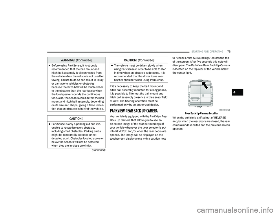
is located on the top rear of the vehicle below
the center light.
Rear Back Up Camera Location
When the vehicle is shifted out of REVERSE
and/or when the rear doors are closed, the rear
camera mode is exited and the previous screen
appears.
Before using ParkSense, it is strongly
recommended that the ball mount and
hitch ball assembly is disconnected from
the vehicle when the vehicle is not used for
towing. Failure to do so can result in injury
or damage to vehicles or obstacles
because the hitch ball will be much closer
to the obstacle than the rear fascia when
the loudspeaker sounds the continuous
tone. Also, the sensors could detect the ball
mount and hitch ball assembly, depending
on its size and shape, giving a false indica -
tion that an obstacle is behind the vehicle.
CAUTION!
ParkSense is only a parking aid and it is
unable to recognize every obstacle,
including small obstacles. Parking curbs
might be temporarily detected or not
detected at all. Obstacles located above or
below the sensors will not be detected
when they are in close proximity.
WARNING! (Continued)
The vehicle must be driven slowly when
using ParkSense in order to be able to stop
in time when an obstacle is detected. It is
recommended that the driver looks over
his/her shoulder when using ParkSense.
CAUTION! (Continued)
4
21_VF_OM_EN_USC_t.book Page 73
Page 76 of 288
74STARTING AND OPERATING
When displayed, static grid lines will illustrate the width of the vehicle and will show separate zones that will help indicate the distance to the rear of
the vehicle. The following table shows the approximate distances for each zone:
NOTE:
If snow, ice, mud, or any foreign substance
builds up on the camera lens, clean the lens,
rinse with water, and dry with a soft cloth.
Do not cover the lens.
Zone
Distance To The Rear Of The Vehicle
Red 0 - 1 ft (0 - 30 cm)
Yellow 1 ft - 3 ft (30 cm - 1 m)
Green 3 ft or greater (1 m or greater)
WARNING!
Drivers must be careful when backing up
even when using the Rear Back Up Camera.
Always check carefully behind your vehicle,
and be sure to check for pedestrians,
animals, other vehicles, obstructions, or blind
spots before backing up. You are responsible
for the safety of your surroundings and must
continue to pay attention while backing up.
Failure to do so can result in serious injury or
death.
CAUTION!
To avoid vehicle damage, ParkView should
only be used as a parking aid. The ParkView
camera is unable to view every obstacle or
object in your drive path.
To avoid vehicle damage, the vehicle must
be driven slowly when using ParkView to be
able to stop in time when an obstacle is
seen. It is recommended that the driver
look frequently over his/her shoulder when
using ParkView.
21_VF_OM_EN_USC_t.book Page 74
Page 78 of 288
76STARTING AND OPERATING
LOOSE FUEL FILLER CAP MESSAGE
If the vehicle diagnostic system determines that
the fuel filler cap is loose, improperly installed,
or damaged, a “Check fuel cap” message will be
displayed in the instrument cluster display
Úpage 44. Tighten the fuel filler cap until a
“clicking” sound is heard. This is an indication
that the fuel filler cap is properly tightened.
If the problem continues, the message will
appear the next time the vehicle is started. See
an authorized dealer as soon as possible.
VEHICLE LOADING
As required by National Highway Traffic Safety
Administration regulations, your vehicle has a
certification label affixed to the driver's side
door or B-pillar.
If seats are removed for carrying cargo, do not
exceed the specified GVWR and GAWR.
VEHICLE CERTIFICATION LABEL
Your vehicle has a Vehicle Certification Label
affixed to the driver’s side B-pillar or the rear of
the driver’s door.
The label contains the following information:
Name of manufacturer
Month and year of manufacture
Gross Vehicle Weight Rating (GVWR)
Gross Axle Weight Rating (GAWR) front and
rear
Vehicle Identification Number (VIN)
Type of vehicle
Month, Day, and Hour of manufacture (MDH)
The bar code allows a computer scanner to read
the VIN.
GROSS VEHICLE WEIGHT RATING
(GVWR)
The GVWR is the total allowable weight of your
vehicle. This includes driver, passengers, and
cargo. The total load must be limited so that you
do not exceed the GVWR.
GROSS AXLE WEIGHT RATING (GAWR)
The GAWR is the maximum capacity of the front
and rear axles. Distribute the load over the front
and rear axles evenly. Make sure that you do
not exceed either front or rear GAWR.
WARNING!
Because the front wheels steer the vehicle, it
is important that you do not exceed the
maximum front or rear GAWR. A dangerous
driving condition can result if either rating is
exceeded. You could lose control of the
vehicle and have a collision.
21_VF_OM_EN_USC_t.book Page 76
Page 90 of 288
88
MULTIMEDIA
UCONNECT SYSTEMS
For detailed information about your
Uconnect 3/3 NAV With 5-inch Display
system Úpage 98.
NOTE:
Uconnect screen images are for illustration
purposes only and may not reflect exact soft -
ware for your vehicle.
CYBERSECURITY
Your vehicle may be a connected vehicle and
may be equipped with both wired and wireless
networks. These networks allow your vehicle to
send and receive information. This information
allows systems and features in your vehicle to
function properly. Your vehicle may be equipped with certain
security features to reduce the risk of
unauthorized and unlawful access to vehicle
systems and wireless communications. Vehicle
software technology continues to evolve over
time and FCA US LLC, working with its suppliers,
evaluates and takes appropriate steps as
needed. Similar to a computer or other devices,
your vehicle may require software updates to
improve the usability and performance of your
systems or to reduce the potential risk of
unauthorized and unlawful access to your
vehicle systems.
The risk of unauthorized and unlawful access to
your vehicle systems may still exist, even if the
most recent version of vehicle software (such as
Uconnect software) is installed.
WARNING!
It is not possible to know or to predict all of
the possible outcomes if your vehicle’s
systems are breached. It may be possible
that vehicle systems, including safety
related systems, could be impaired or a
loss of vehicle control could occur that may
result in an accident involving serious injury
or death.
ONLY insert media (e.g., USB, SD card, or
CD) into your vehicle if it came from a
trusted source. Media of unknown origin
could possibly contain malicious software,
and if installed in your vehicle, it may
increase the possibility for vehicle systems
to be breached.
As always, if you experience unusual
vehicle behavior, take your vehicle to your
nearest authorized dealer immediately.
21_VF_OM_EN_USC_t.book Page 88
Page 92 of 288
90MULTIMEDIA
UCONNECT 3/3 NAV SETTINGS
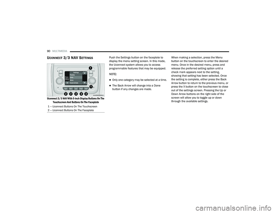
Uconnect 3/3 NAV With 5-inch Display Buttons On The
Touchscreen And Buttons On The Faceplate
Push the Settings button on the faceplate to
display the menu setting screen. In this mode,
the Uconnect system allows you to access
programmable features that may be equipped.
NOTE:
Only one category may be selected at a time.
The Back Arrow will change into a Done
button if any changes are made.
When making a selection, press the Menu
button on the touchscreen to enter the desired
menu. Once in the desired menu, press and
release the preferred setting option until a
check mark appears next to the setting,
showing that setting has been selected. Once
the setting is complete, either press the Back
Arrow button to return to the previous menu, or
press the X button on the touchscreen to close
out of the settings screen. Pressing the Up or
Down Arrow buttons on the right side of the
screen will allow you to toggle up or down
through the available settings.
1 — Uconnect Buttons On The Touchscreen
2 — Uconnect Buttons On The Faceplate
21_VF_OM_EN_USC_t.book Page 90
Page 93 of 288
MULTIMEDIA91
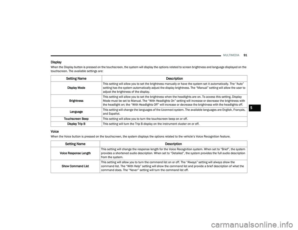
Display
When the Display button is pressed on the touchscreen, the system will display the options related to screen brightness and language displayed on the
touchscreen. The available settings are:
Voice
When the Voice button is pressed on the touchscreen, the system displays the options related to the vehicle’s Voice Recognition feature.
Setting Name Description
Display ModeThis setting will allow you to set the brightness manually or have the system set it automatically. The “Auto”
setting has the system automatically adjust the display brightness. The “Manual” setting will allow the user to
adjust the brightness of the display.
Brightness This setting will allow you to set the brightness when the headlights are on. To access this setting, Display
Mode must be set to Manual. The “With Headlights On” setting will increase or decrease the brightness with
the headlight on; the “With Headlights Off” will increase or decrease the brightness with the headlights off.
Language This setting will change the languages of the Uconnect system. The available languages are English, Français,
and Español.
Touchscreen Beep This setting will allow you to turn the touchscreen beep on or off.
Display Trip B This setting will turn the Trip B display on the instrument cluster on or off.
Setting Name Description
Voice Response LengthThis setting will change the response length for the Voice Recognition system. When set to “Brief”, the system
provides a shortened audio description. When set to “Detailed”, the system provides the full audio description
from the system.
Show Command List This setting will allow you to turn the command list on or off. The “Always” setting will always show the
command list. The “With Help” setting will show the command list and provide a brief description of what the
command does. The “Never” setting will turn the command list off.
5
21_VF_OM_EN_USC_t.book Page 91
Page 94 of 288
92MULTIMEDIA
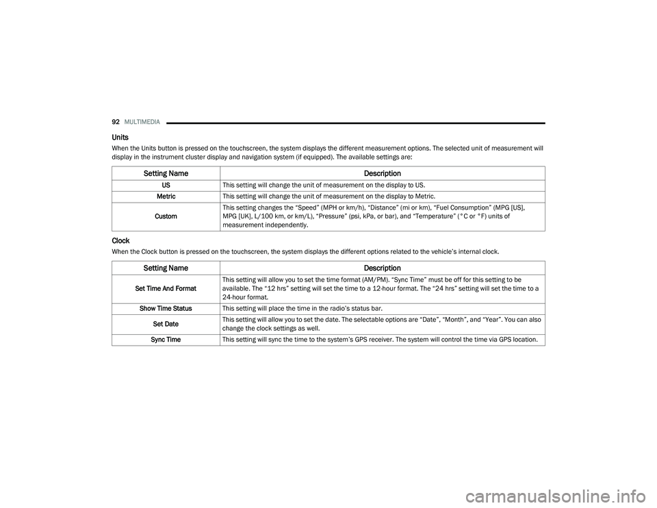
Units
When the Units button is pressed on the touchscreen, the system displays the different measurement options. The selected unit of measurement will
display in the instrument cluster display and navigation system (if equipped). The available settings are:
Clock
When the Clock button is pressed on the touchscreen, the system displays the different options related to the vehicle’s internal clock.
Setting Name Description
USThis setting will change the unit of measurement on the display to US.
Metric This setting will change the unit of measurement on the display to Metric.
Custom This setting changes the “Speed” (MPH or km/h), “Distance” (mi or km), “Fuel Consumption” (MPG [US],
MPG [UK], L/100 km, or km/L), “Pressure” (psi, kPa, or bar), and “Temperature” (°C or °F) units of
measurement independently.
Setting Name
Description
Set Time And FormatThis setting will allow you to set the time format (AM/PM). “Sync Time” must be off for this setting to be
available. The “12 hrs” setting will set the time to a 12-hour format. The “24 hrs” setting will set the time to a
24-hour format.
Show Time Status This setting will place the time in the radio’s status bar.
Set Date This setting will allow you to set the date. The selectable options are “Date”, “Month”, and “Year”. You can also
change the clock settings as well.
Sync Time This setting will sync the time to the system’s GPS receiver. The system will control the time via GPS location.
21_VF_OM_EN_USC_t.book Page 92
Page 95 of 288
MULTIMEDIA93
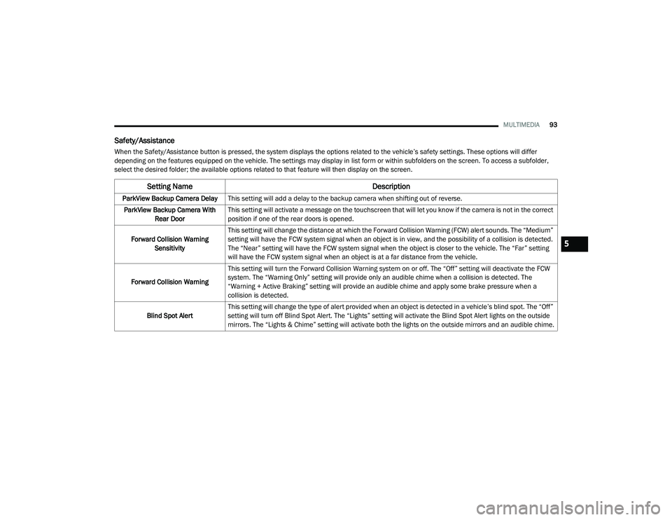
Safety/Assistance
When the Safety/Assistance button is pressed, the system displays the options related to the vehicle’s safety settings. These options will differ
depending on the features equipped on the vehicle. The settings may display in list form or within subfolders on the screen. To access a subfolder,
select the desired folder; the available options related to that feature will then display on the screen.
Setting Name Description
ParkView Backup Camera DelayThis setting will add a delay to the backup camera when shifting out of reverse.
ParkView Backup Camera With Rear Door This setting will activate a message on the touchscreen that will let you know if the camera is not in the correct
position if one of the rear doors is opened.
Forward Collision Warning Sensitivity This setting will change the distance at which the Forward Collision Warning (FCW) alert sounds. The “Medium”
setting will have the FCW system signal when an object is in view, and the possibility of a collision is detected.
The “Near” setting will have the FCW system signal when the object is closer to the vehicle. The “Far” setting
will have the FCW system signal when an object is at a far distance from the vehicle.
Forward Collision Warning This setting will turn the Forward Collision Warning system on or off. The “Off” setting will deactivate the FCW
system. The “Warning Only” setting will provide only an audible chime when a collision is detected. The
“Warning + Active Braking” setting will provide an audible chime and apply some brake pressure when a
collision is detected.
Blind Spot Alert This setting will change the type of alert provided when an object is detected in a vehicle’s blind spot. The “Off”
setting will turn off Blind Spot Alert. The “Lights” setting will activate the Blind Spot Alert lights on the outside
mirrors. The “Lights & Chime” setting will activate both the lights on the outside mirrors and an audible chime.
5
21_VF_OM_EN_USC_t.book Page 93
Page 96 of 288
94MULTIMEDIA
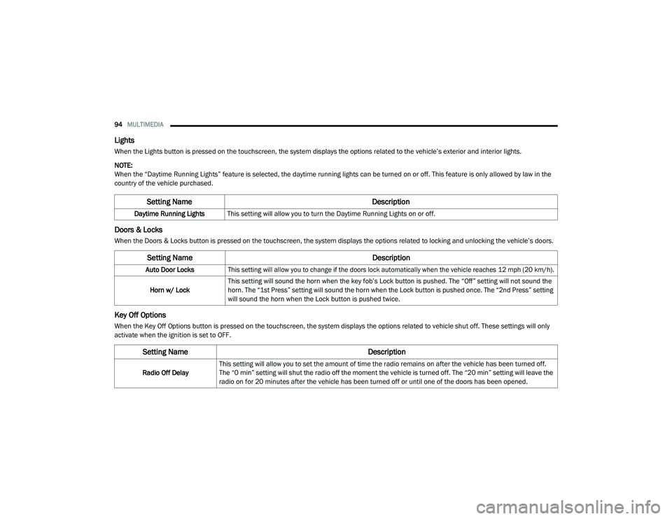
Lights
When the Lights button is pressed on the touchscreen, the system displays the options related to the vehicle’s exterior and interior lights.
NOTE:
When the “Daytime Running Lights” feature is selected, the daytime running lights can be turned on or off. This feature is only allowed by law in the
country of the vehicle purchased.
Doors & Locks
When the Doors & Locks button is pressed on the touchscreen, the system displays the options related to locking and unlocking the vehicle’s doors.
Key Off Options
When the Key Off Options button is pressed on the touchscreen, the system displays the options related to vehicle shut off. These settings will only
activate when the ignition is set to OFF.
Setting Name Description
Daytime Running LightsThis setting will allow you to turn the Daytime Running Lights on or off.
Setting Name Description
Auto Door Locks
This setting will allow you to change if the doors lock automatically when the vehicle reaches 12 mph (20 km/h).
Horn w/ Lock This setting will sound the horn when the key fob’s Lock button is pushed. The “Off” setting will not sound the
horn. The “1st Press” setting will sound the horn when the Lock button is pushed once. The “2nd Press” setting
will sound the horn when the Lock button is pushed twice.
Setting Name
Description
Radio Off DelayThis setting will allow you to set the amount of time the radio remains on after the vehicle has been turned off.
The “0 min” setting will shut the radio off the moment the vehicle is turned off. The “20 min” setting will leave the
radio on for 20 minutes after the vehicle has been turned off or until one of the doors has been opened.
21_VF_OM_EN_USC_t.book Page 94