display RAM PROMASTER 2021 Workshop Manual
[x] Cancel search | Manufacturer: RAM, Model Year: 2021, Model line: PROMASTER, Model: RAM PROMASTER 2021Pages: 288, PDF Size: 15.22 MB
Page 126 of 288

124MULTIMEDIA
To enable Siri, push and hold, then release the
Uconnect Voice Recognition (VR) button on the
steering wheel. After you hear a double beep,
you can ask Siri to play podcasts and music, get
directions, read text messages, and many other
useful requests.
Bluetooth® Communication Link
Mobile phones may lose connection to the
Uconnect Phone. When this happens, the
connection can generally be re-established by
restarting the mobile phone. Your mobile phone
is recommended to remain in Bluetooth® ON
mode.
Power-Up
After switching the ignition key from OFF to
either the ON/RUN or ACC position, or after a
language change, you must wait at least
15 seconds prior to using the system
Úpage 274.NAVIGATION MODE — IF EQUIPPED
OPERATING NAVIGATION MODE — IF
E
QUIPPED
Planning A Route
Using the search bar provides a wide range of
ways to find places and then navigate to them.
You can search for your destination in different
ways:
A specific address
A partial address
A type of place
A zip code
A city to navigate to a city center
A Point of Interest (POI) near your current
location
Latitude and longitude coordinates Using Search
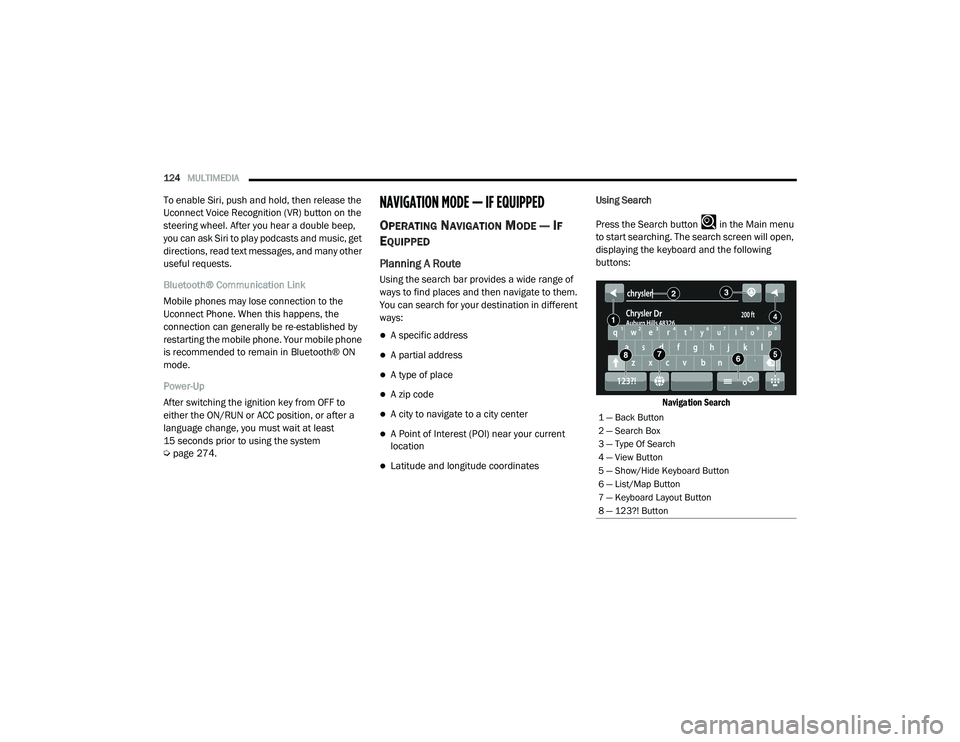
Press the Search button in the Main menu
to start searching. The search screen will open,
displaying the keyboard and the following
buttons:
Navigation Search
1 — Back Button
2 — Search Box
3 — Type Of Search
4 — View Button
5 — Show/Hide Keyboard Button
6 — List/Map Button
7 — Keyboard Layout Button
8 — 123?! Button
21_VF_OM_EN_USC_t.book Page 124
Page 140 of 288

138MULTIMEDIA
Feature Description
Back ButtonPress the Back button to return to an overview of the route. If no route is planned,
pressing this button moves the map to put your current location at the center.
Map Symbols Symbols are used on the map to show the destination and saved places Ú
page 142.
Map symbols include:
Your destination
Your home location
A stop on your route
A location saved in My Places
Traffic Information — If Equipped Select the Traffic Information button to display information about traffic delays.
Selected Location Press and hold the Selected Location button to select a location on the map. Select the
Pop-up Menu button to show options for the location, or select the Drive button to plan
a route to the location.
Current Location This symbol shows your current location on the map.
Your Route If you have a planned route, it will appear on the map. You can select the route to clear
it, change the route type, add a stop, or save changes to your route Ú
page 130.
Main Menu Button Press the Main Menu button to open the main menu.
Zoom Button Press the zoom in + button to zoom in and the zoom out – button to zoom out.
Switch View Button Press the Switch View button to change between the map view and the guidance view.
21_VF_OM_EN_USC_t.book Page 138
Page 144 of 288

142MULTIMEDIA
Points Of Interest
About Points Of Interest
Points Of Interest (POI) are useful places on the
map.
Here are some examples:
Restaurants
Hotels
Museums
Parking lots
Gas stations
Emergency Services
Using POIs To Plan A Route
When you plan a route, you can use a POI for the
destination or as a stop along the route. Using Search
1. Select “Search” on the Main Menu to begin
a search. The search screen will open,
displaying the keyboard. Enter the name of
your desired destination. Your search
results will be displayed in two lists.
Addresses and city matches are shown in
the list called “Addresses.” POIs, types of
POIs, and Places are shown in the list
called “Points of Interest.” You can also
select a POI category to only see POI
search results from that category.
2. Select the desired POI. The location will appear on the map. From here, you can
save the POI to “My Places,” use this POI as
a starting point, begin navigation to this
destination, or view more details about this
POI. By pressing “More Information,” you
can view the phone number and full
address of the POI.
3. If a route is already planned, you can add the location to your current route. To plan a
route to this destination, press the Drive
button on the touchscreen. NOTE:
Your navigation system will calculate a route,
and guidance to your destination will begin.
Guidance view will begin as soon as you start
driving.
My Places
About My Places
My Places provides an easy way to
select a location without the need to
enter the address or search for the
location. You can use My Places to
create a collection of useful or favorite
addresses.
The following items are always in My Places:
Home : Your home location can be your home
address or somewhere you often visit. This
feature provides an easy way to navigate
there.
Recent Destinations: Select this button to
select your destination from a list of locations
you have recently navigated to.
21_VF_OM_EN_USC_t.book Page 142
Page 161 of 288

SAFETY159
NOTE:
Whenever an audible alert is requested by the
BSM system, the radio is also muted.
When the system is in RCP, the system shall
respond with both visual and audible alerts
when a detected object is present. Whenever
an audible alert is requested, the radio is also
muted. Turn/hazard signal status is ignored;
the RCP state always requests the chime.
Blind Spot Alert Off
When the BSM system is turned off there will be
no visual or audible alerts from either the BSM
or RCP systems.
NOTE:
The BSM system will store the current operating
mode when the vehicle is shut off. Each time
the vehicle is started the previously stored
mode will be recalled and used.
FORWARD COLLISION WARNING (FCW)
W
ITH MITIGATION — IF EQUIPPED
The FCW with Mitigation system provides the
driver with audible warnings, visual warnings
(within the instrument cluster display), and may
apply a brake jerk to warn the driver when it
detects a potential frontal collision. The warnings and limited braking are intended
to provide the driver with enough time to react,
avoid or mitigate the potential collision.
NOTE:
FCW monitors the information from the forward
looking sensors as well as the Electronic Brake
Controller (EBC), to calculate the probability of a
forward collision. When the system determines
that a forward collision is probable, the driver
will be provided with audible and visual warn-
ings as well as a possible brake jerk warning.
If the driver does not take action based upon
these progressive warnings, then the system
will provide a limited level of active braking to
help slow the vehicle and mitigate the potential
forward collision. If the driver reacts to the warn
-
ings by braking and the system determines that
the driver intends to avoid the collision by
braking but has not applied sufficient brake
force, the system will compensate and provide
additional brake force as required.
If a FCW with Mitigation event begins at a speed
below 26 mph (42 km/h), the system may
provide the maximum braking possible to miti -
gate the potential forward collision. Vehicles
With Automatic Transmission: After the end of the intervention of automatic braking, the trans
-
mission may remain in last gear stored — there -
fore the vehicle could lurch forward, once the
brakes release a few seconds later. If the
Forward Collision Warning with Mitigation event
stops the vehicle completely, the system will
hold the vehicle at standstill for two seconds
and then release the brakes.
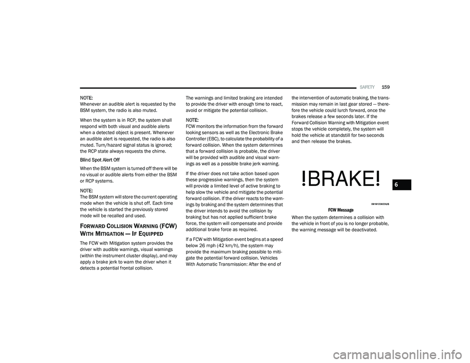
FCW Message
When the system determines a collision with
the vehicle in front of you is no longer probable,
the warning message will be deactivated.
6
21_VF_OM_EN_USC_t.book Page 159
Page 162 of 288

160SAFETY
NOTE:
The minimum speed for FCW activation is
3 mph (5 km/h).
The FCW alerts may be triggered on objects
other than vehicles such as guard rails or
sign posts based on the course prediction.
This is expected and is a part of normal FCW
activation and functionality.
It is unsafe to test the FCW system. To
prevent such misuse of the system the Active
Braking portion of FCW will be deactivated for
the first 20 seconds from braking actuation.
The FCW system is intended for on-road use
only. If the vehicle is taken off-road, the FCW
system should be deactivated to prevent
unnecessary warnings to the surroundings.
FCW may not react to irrelevant objects such
as overhead objects, ground reflections,
objects not in the path of the vehicle,
stationary objects that are far away,
oncoming traffic, or leading vehicles with the
same or higher rate of speed.
FCW will be disabled like ACC, with the
unavailable screens Ú page 274.
Turning FCW On or Off
The FCW button is located in the Uconnect
display in the control settings Úpage 89.
To turn the FCW system on, press the forward
collision button once.
To turn the FCW system off, press the forward
collision button once.
NOTE:
Changing the FCW status to “Off” deactivates
the system, so no warning or active braking
will be available in case of a possible colli -
sion.
Changing the FCW status to “Only Warning”
prevents the system from providing limited
active braking, or additional brake support if the driver is not braking adequately in the
event of a potential frontal collision, but
maintains the audible and visual warnings.
When FCW status is set to “Warning and
Braking”, this allows the system to warn the
driver of a possible collision with the vehicle
in front using audible/visual warnings and it
applies autonomous braking.
The FCW system state is kept in memory from
one ignition position to the next. If the system
is turned off, it will maintain its status in the
next key cycle.
FCW Braking Status And Sensitivity
The FCW Sensitivity and Active Braking status
are programmable through the Uconnect
system Ú
page 89.
Far
When the sensitivity of FCW is set to the
“Far” setting and the system status is
“Only Warning”, this allows the system to
warn the driver of a possible more distant
collision with the vehicle in front using
audible/visual warnings.
WARNING!
Forward Collision Warning (FCW) is not
intended to avoid a collision on its own, nor
can FCW detect every type of potential
collision. The driver has the responsibility to
avoid a collision by controlling the vehicle via
braking and steering. Failure to follow this
warning could lead to serious injury or death.
21_VF_OM_EN_USC_t.book Page 160
Page 163 of 288

SAFETY161
More cautious drivers that do not mind
frequent warnings may prefer this
setting.
Medium
When the sensitivity of FCW is set to the
“Medium” setting and the system status
is “Only Warning”, this allows the system
to warn the driver of a possible collision
with the vehicle in front using audible/
visual warnings.
Near
When the sensitivity of FCW is set to the
“Near” setting and the system status is
“Only Warning”, this allows the system to
warn the driver of a possible closer colli -
sion with the vehicle in front using
audible/visual warnings.
This setting provides less reaction time
than the “Far” and “Medium” settings,
which allows for a more dynamic driving
experience.
More dynamic or aggressive drivers that
want to avoid frequent warnings may
prefer this setting.
FCW Limited Warning
If the instrument cluster displays “FCW Limited
Functionality” or “FCW Limited Functionality
Clean Front Windshield” momentarily, there
may be a condition that limits FCW functionality.
Although the vehicle is still drivable under
normal conditions, the active braking may not
be fully available. Once the condition that
limited the system performance is no longer
present, the system will return to its full
performance state. If the problem persists, see
an authorized dealer.
Service FCW Warning
If the system turns off, and the instrument
cluster displays: “FCW Unavailable Service
Required”, this indicates there is an internal
system fault. Although the vehicle is still
drivable under normal conditions, have the
system checked by an authorized dealer.
TIRE PRESSURE MONITORING SYSTEM
(TPMS)
The Tire Pressure Monitoring System (TPMS)
will warn the driver of a low tire pressure based
on the vehicle recommended cold placard
pressure.
The tire pressure will vary with temperature by
about 1 psi (7 kPa) for every 12°F (6.5°C). This
means that when the outside temperature
decreases, the tire pressure will decrease. Tire
pressure should always be set based on cold
inflation tire pressure. This is defined as the tire
pressure after the vehicle has not been driven
for at least three hours, or driven less than
1 mile (1.6 km) after a three hour period. The
cold tire inflation pressure must not exceed the
maximum inflation pressure molded into the
tire sidewall. The tire pressure will also increase
as the vehicle is driven — this is normal and
there should be no adjustment for this
increased pressure.
See Úpage 240 on how to properly inflate the
vehicle’s tires.
6
21_VF_OM_EN_USC_t.book Page 161
Page 165 of 288

SAFETY163
NOTE:
The TPMS is not intended to replace normal
tire care and maintenance or to provide
warning of a tire failure or condition.
The TPMS should not be used as a tire pres -
sure gauge while adjusting your tire pressure.
Driving on a significantly underinflated tire
causes the tire to overheat and can lead to
tire failure. Underinflation also reduces fuel
efficiency and tire tread life, and may affect
the vehicle’s handling and stopping ability.
The TPMS is not a substitute for proper tire
maintenance, and it is the driver’s responsi -
bility to maintain correct tire pressure using
an accurate tire pressure gauge, even if
underinflation has not reached the level to
trigger illumination of the TPMS Warning
Light.
Seasonal temperature changes will affect
tire pressure, and the TPMS will monitor the
actual tire pressure in the tire Ú page 274.
Base System
This is the TPMS warning indicator
located in the instrument cluster.
The TPMS uses wireless technology with wheel
rim mounted electronic sensors to monitor tire
pressure levels. Sensors, mounted to each
wheel as part of the valve stem, transmit tire
pressure readings to the Receiver Module.
NOTE:
It is particularly important for you to check the
tire pressure in all of the tires on your vehicle
regularly and to maintain the proper pressure.
The TPMS consists of the following
components:
Receiver Module
Four Tire Pressure Monitoring System
sensors
Tire Pressure Monitoring System Warning
Light
Tire Pressure Monitoring Low Pressure
Warnings
The Tire Pressure Monitoring System Warning
Light will illuminate in the instrument cluster, an
audible chime will be activated, and the “Check
tire pressure” message will display when one or
more of the four active road tire pressures are
low. Should this occur, you should stop as soon
as possible, check the inflation pressure of
each tire on your vehicle, and inflate each tire to
the vehicle’s recommended cold placard
pressure value. The system will automatically
update and the Tire Pressure Monitoring
System warning Light will extinguish once the
updated tire pressures have been received.
The vehicle may need to be driven for up to
20 minutes above 15 mph (24 km/h) to receive
this information.
6
21_VF_OM_EN_USC_t.book Page 163
Page 166 of 288

164SAFETY
Check TPMS Warnings
The Tire Pressure Monitoring System Warning
Light will flash on and off for 75 seconds and
remain on solid when a system fault is detected,
an audible chime will be activated and the “Tire
Pressure Monitoring Unavailable” message will
display. If the ignition key is cycled, this
sequence will repeat providing the system fault
still exists. The TPMS Warning Light will turn off
when the fault condition no longer exists. A
system fault can occur with any of the following
scenarios:
Jamming due to electronic devices or driving
next to facilities emitting the same radio
frequencies as the TPMS sensors
Installing some form of aftermarket window
tinting that affects radio wave signals
Snow or ice around the wheels or wheel
housings
Using tire chains on the vehicle
Using wheels/tires not equipped with TPMS
sensors NOTE:
Your vehicle is equipped with a regular size
spare wheel.
1. The spare tire does not have a TPMS
sensor. Therefore, the TPMS will not
monitor the pressure in the spare tire.
2. If a spare tire not equipped with the Tire Pressure Monitoring system sensor is used,
the TPMS Warning Light will turn on,
flashing for 75 seconds and then remaining
solid for each subsequent ignition key cycle.
3. Once you repair or replace the original road tire and reinstall it on the vehicle in place of
the spare tire, the TPMS will update
automatically and the Tire Pressure
Monitoring System Warning Light will
extinguish once the updated tire pressures
have been received. The vehicle may need
to be driven for up to 20 minutes above
15 mph (24 km/h) to receive this
information.
NOTE:
For correct Tire Pressure Monitoring System
behavior, please wait for about 20 minutes in
key-off during each tire substitution.
OCCUPANT RESTRAINT SYSTEMS
Some of the most important safety features in
your vehicle are the restraint systems:
OCCUPANT RESTRAINT SYSTEMS
F
EATURES
Seat Belt Systems
Supplemental Restraint Systems (SRS) Air
Bags
Child Restraints
Some of the safety features described in this
section may be standard equipment on some
models, or may be optional equipment on others.
If you are not sure, ask an authorized dealer.
IMPORTANT SAFETY PRECAUTIONS
Please pay close attention to the information in
this section. It tells you how to use your restraint
system properly, to keep you and your
passengers as safe as possible.
21_VF_OM_EN_USC_t.book Page 164
Page 213 of 288

211
SERVICING AND MAINTENANCE
SCHEDULED SERVICING
Your vehicle is equipped with an automatic oil
change indicator system. The oil change
indicator system will remind you that it is time to
take your vehicle in for scheduled maintenance.
Based on engine operation conditions, the oil
change indicator message will illuminate in the
instrument cluster. This means that service is
required for your vehicle. Operating conditions
such as frequent short-trips, trailer tow, and
extremely hot or cold ambient temperatures will
influence when the “Oil Change Required”
message is displayed. Severe Operating
Conditions can cause the change oil message to
illuminate as early as 3,500 miles (5,600 km)
since last reset. Have the vehicle serviced as
soon as possible, within the next 500 miles
(805 km).
An authorized dealer will reset the oil change
indicator message after completing the
scheduled oil change. If a scheduled oil change
is performed by someone other than an
authorized dealer, the message can be reset by
referring to the steps described under
Instrument Cluster Display Ú
page 45.
NOTE:
Under no circumstances should oil change
intervals exceed 10,000 miles (16,000 km),
12 months or 350 hours of engine run time,
whichever comes first. The 350 hours of engine
run or idle time is generally only a concern for
fleet customers. Severe Duty All Models
Vehicles that are operated in a dusty and off-road
environment, or predominately at idle or very low
engine RPM are known as Severe Duty vehicles.
It is recommended that you change the engine oil
at 4,000 miles (6,500 km) or 350 hours of
engine run time.
Once A Month Or Before A Long Trip:
Check engine oil level
Check windshield washer fluid level
Check the tire pressures and look for unusual
wear or damage. Rotate at the first sign of
irregular wear, even if it occurs before the oil
indicator system turns on
Check the fluid levels of the coolant reservoir,
brake master cylinder, and power steering
and fill as needed
Check function of all interior and exterior
lights
8
21_VF_OM_EN_USC_t.book Page 211
Page 280 of 288

278 H
Hazard Driving Through Flowing, Rising, OrShallow Standing Water
.......................... 86Hazard Warning Flashers.............................. 190Head Restraints............................................... 20HeadlightsCleaning.................................................... 260High Beam.................................................. 26High Beam/Low Beam Select Switch.......... 26Passing........................................................ 26Switch......................................................... 26Heated Mirrors................................................ 25Heated Seats................................................... 19Heater, Engine Block....................................... 58High Beam/Low Beam Select (Dimmer)
Switch.............................................................. 26Hill Start Assist.............................................. 153HitchesTrailer Towing.............................................. 80Hood Prop........................................................ 40Hood Release.................................................. 40
I
Ignition............................................................ 12Key....................................................... 10, 12Switch......................................................... 12Ignition Key Removal....................................... 12Illuminated Entry............................................. 30
Immobilizer (Sentry Key).................................. 12Inside Rearview Mirror..................................... 23Instrument Cluster.................................... 42, 54Display......................................................... 44Instrument Panel Lens Cleaning................... 262Interior And Instrument Lights......................... 28Interior Appearance Care.............................. 261Interior Lights................................................... 28Intermittent Wipers (Delay Wipers).................. 30iPod/USB/MP3 Control.................................... 37
J
Jack Location................................................ 190Jack Operation.............................................. 190Jacking And Tire Changing............................ 190Jacking And Tire Changing Instructions........ 191Jump Starting............................................... 203
K
Key FobProgramming Additional Key Fobs
............... 11Key Fob Battery Service
(Remote Keyless Entry).................................... 11Key Fob Programming
(Remote Keyless Entry).................................... 11Key-In Reminder.............................................. 12Keys................................................................. 10Replacement............................................... 11Sentry (Immobilizer).................................... 12
L
Lane Change Assist..........................................27Lap/Shoulder Belts....................................... 166Latches......................................................... 188Hood............................................................40Lead Free Gasoline....................................... 265Leaks, Fluid................................................... 189Life Of Tires................................................... 251Light Bulbs........................................... 188, 235Lights............................................................ 188Air Bag...................................... 48, 173, 187Brake Assist Warning................................ 152Brake Warning.............................................49Bulb Replacement.................................... 235Cruise..........................................................54Daytime Running.........................................26Dimmer Switch, Headlight...........................26Electronic Stability Program(ESP) Indicator........................................ 49, 152Exterior.............................................. 26, 188Hazard Warning Flasher........................... 190Headlights...................................................26High Beam...................................................26Illuminated Entry.........................................30Interior.........................................................28Malfunction Indicator (Check Engine)..........52Park......................................................26, 54Passing........................................................26
21_VF_OM_EN_USC_t.book Page 278