warning RAM PROMASTER 2022 Owner's Manual
[x] Cancel search | Manufacturer: RAM, Model Year: 2022, Model line: PROMASTER, Model: RAM PROMASTER 2022Pages: 268, PDF Size: 13.26 MB
Page 32 of 268
30GETTING TO KNOW YOUR VEHICLE
Digital Rearview Mirror — If Equipped
The Digital Rearview Mirror provides a high
definition, wide and unobstructed view of the road
behind while driving.
Position the mirror in the regular Automatic
Dimming Mirror mode, then activate the Digital
Rearview Mirror mode.
To activate the Digital Rearview Mirror, pull the
on/off control lever on the bottom of the mirror
rearward toward the driver.
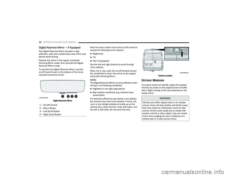
Digital Rearview Mirror
Push the menu button next to the on/off control to
access the following mirror options:Brightness
Tilt
Pan (if equipped)
Use the left and right buttons to scroll through
menu options.
When not in use, push the on/off forward toward
the windshield to return the mirror to the regular
Automatic Dimming Mirror.
NOTE:The Digital Rearview Mirror is not as effective when
driving in the following conditions:
Nighttime in low light applications
Bad weather conditions (e.g. extreme haze,
snow/slush)
If it becomes difficult to see clearly in the display,
the camera may need to be cleaned. If snow, ice,
mud, or any foreign substance builds up on the
camera lens, clean the lens, rinse with water, and
dry with a soft cloth. Do not cover the lens.
Camera Location
OUTSIDE MIRRORS
To receive maximum benefit, adjust the outside
mirror(s) to center on the adjacent lane of traffic
with a slight overlap of the view obtained on the
inside mirror.
1 — On/Off Control
2 — Menu Button
3 — Left Scroll Button
4 — Right Scroll Button
WARNING!
Vehicles and other objects seen in an outside
convex mirror will look smaller and farther away
than they really are. Relying too much on side
convex mirrors could cause you to collide with
another vehicle or other object. Use your inside
mirror when judging the size or distance of a
vehicle seen in a side convex mirror.
22_VF_OM_EN_USC_t.book Page 30
Page 34 of 268
32GETTING TO KNOW YOUR VEHICLE
Forward Folding
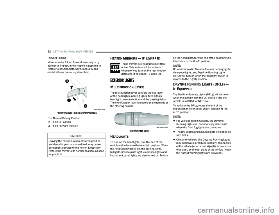
Mirrors can be folded forward manually or by
accidental impact. In this case it is possible to
restore to position both ways, manually and
electrically (as previously described).
Power/Manual Folding Mirror Positions
HEATED MIRRORS — IF EQUIPPED
These mirrors are heated to melt frost
or ice. This feature will be activated
whenever you turn on the rear window
defroster (if equipped) Ú page 39.
EXTERIOR LIGHTS
MULTIFUNCTION LEVER
The multifunction lever controls the operation
of the headlights, parking lights, turn signals,
headlight beam selection and the passing lights.
The multifunction lever is located on the left side of
the steering column.
Multifunction Lever
HEADLIGHTS
To turn on the headlights, turn the end of the
multifunction lever to the headlight position. When
the headlight switch is on, the parking lights,
taillights, license plate light, clearance lights and
instrument panel lights are also turned on. To turn off the headlights, turn the end of the multifunction
lever back to the O (off) position.
NOTE:On vehicles sold in Canada, the rear parking lights,
clearance lights, and Daytime Running Lights
(DRLs) will turn on when the headlight switch is
rotated to the O (off) position.
DAYTIME RUNNING LIGHTS (DRLS) —
I
F EQUIPPED
The Daytime Running Lights (DRLs) will come on
when the ignition is in the ON position and the
vehicle is in DRIVE or NEUTRAL.
To activate the DRLs, rotate the end of the
multifunction lever to the O (off) position or the
AUTO position.
NOTE:
For vehicles sold in Canada, the Daytime
Running Lights will automatically deactivate
when the front fog lights are turned on.
The low beams and side/taillights will not be on
with DRLs.
On some vehicles, the Daytime Running Lights
may deactivate, or reduce intensity, on one side
of the vehicle (when a turn signal is activated on
that side), or on both sides of the vehicle (when
the hazard warning lights are activated).
1 — Normal Driving Position
2 — Fold In Position
3 — Fold Forward Position
CAUTION!
Leaving the mirror in a non-powered position,
accidental impact or manual fold, may cause
permanent damage to the mirror. Electrically
restore the mirror to its normal position, as soon
as practical.
22_VF_OM_EN_USC_t.book Page 32
Page 40 of 268
38GETTING TO KNOW YOUR VEHICLE
WIPERS AND WASHERS
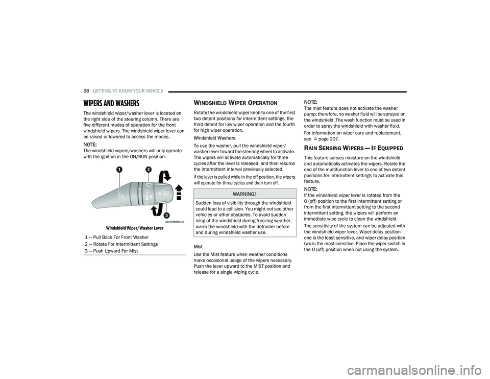
The windshield wiper/washer lever is located on
the right side of the steering column. There are
five different modes of operation for the front
windshield wipers. The windshield wiper lever can
be raised or lowered to access the modes.
NOTE:The windshield wipers/washers will only operate
with the ignition in the ON/RUN position.
Windshield Wiper/Washer Lever
WINDSHIELD WIPER OPERATION
Rotate the windshield wiper knob to one of the first
two detent positions for intermittent settings, the
third detent for low wiper operation and the fourth
for high wiper operation.
Windshield Washers
To use the washer, pull the windshield wiper/
washer lever toward the steering wheel to activate.
The wipers will activate automatically for three
cycles after the lever is released, and then resume
the intermittent interval previously selected.
If the lever is pulled while in the off position, the wipers
will operate for three cycles and then turn off.
Mist
Use the Mist feature when weather conditions
make occasional usage of the wipers necessary.
Push the lever upward to the MIST position and
release for a single wiping cycle.
NOTE:The mist feature does not activate the washer
pump; therefore, no washer fluid will be sprayed on
the windshield. The wash function must be used in
order to spray the windshield with washer fluid.
For information on wiper care and replacement,
see Úpage 207.
RAIN SENSING WIPERS — IF EQUIPPED
This feature senses moisture on the windshield
and automatically activates the wipers. Rotate the
end of the multifunction lever to one of two detent
positions for intermittent settings to activate this
feature.
NOTE:If the windshield wiper lever is rotated from the
O (off) position to the first intermittent setting or
from the first intermittent setting to the second
intermittent setting, the wipers will perform an
immediate wipe cycle to clean the windshield.
The sensitivity of the system can be adjusted with
the windshield wiper lever. Wiper delay position
one is the least sensitive, and wiper delay position
two is the most sensitive. Place the wiper switch in
the O (off) position when not using the system.
1 — Pull Back For Front Washer
2 — Rotate For Intermittent Settings
3 — Push Upward For MistWARNING!
Sudden loss of visibility through the windshield
could lead to a collision. You might not see other
vehicles or other obstacles. To avoid sudden
icing of the windshield during freezing weather,
warm the windshield with the defroster before
and during windshield washer use.
22_VF_OM_EN_USC_t.book Page 38
Page 47 of 268
GETTING TO KNOW YOUR VEHICLE45
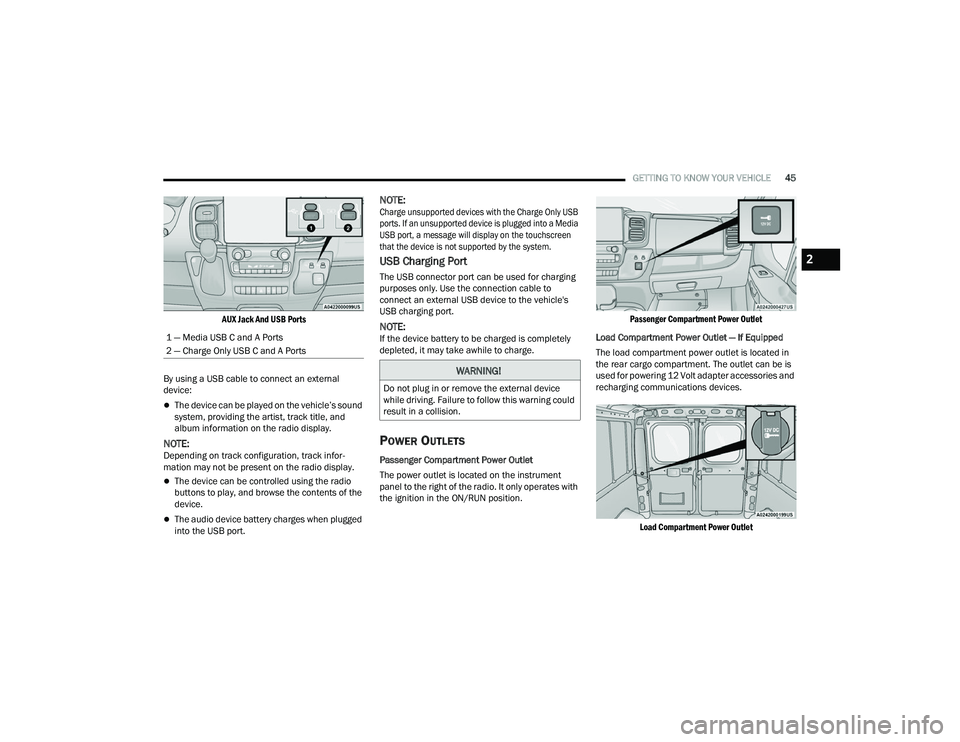
AUX Jack And USB Ports
By using a USB cable to connect an external
device:
The device can be played on the vehicle’s sound
system, providing the artist, track title, and
album information on the radio display.
NOTE:Depending on track configuration, track infor -
mation may not be present on the radio display.
The device can be controlled using the radio
buttons to play, and browse the contents of the
device.
The audio device battery charges when plugged
into the USB port.
NOTE:
Charge unsupported devices with the Charge Only USB
ports. If an unsupported device is plugged into a Media
USB port, a message will display on the touchscreen
that the device is not supported by the system.
USB Charging Port
The USB connector port can be used for charging
purposes only. Use the connection cable to
connect an external USB device to the vehicle's
USB charging port.
NOTE:If the device battery to be charged is completely
depleted, it may take awhile to charge.
POWER OUTLETS
Passenger Compartment Power Outlet
The power outlet is located on the instrument
panel to the right of the radio. It only operates with
the ignition in the ON/RUN position.
Passenger Compartment Power Outlet
Load Compartment Power Outlet — If Equipped
The load compartment power outlet is located in
the rear cargo compartment. The outlet can be is
used for powering 12 Volt adapter accessories and
recharging communications devices.
Load Compartment Power Outlet
1 — Media USB C and A Ports
2 — Charge Only USB C and A Ports
WARNING!
Do not plug in or remove the external device
while driving. Failure to follow this warning could
result in a collision.
2
22_VF_OM_EN_USC_t.book Page 45
Page 48 of 268
46GETTING TO KNOW YOUR VEHICLE
(Continued)
NOTE:Do not connect devices with power higher than
180 W to the socket. Do not damage the socket by
using unsuitable adapters.
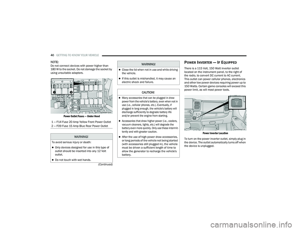
Power Outlet Fuses — Under Hood
POWER INVERTER — IF EQUIPPED
There is a 115 Volt, 150 Watt inverter outlet
located on the instrument panel, to the right of
the radio, to convert DC current to AC current.
This outlet can power cellular phones, electronics
and other low power devices requiring power up to
150 Watts. Certain game consoles will exceed this
power limit, as will most power tools.
Power Inverter Location
To turn on the power inverter outlet, simply plug in
the device. The outlet automatically turns off when
the device is unplugged.
1 — F14 Fuse 20 Amp Yellow Front Power Outlet
2 — F09 Fuse 15 Amp Blue Rear Power Outlet
WARNING!
To avoid serious injury or death:
Only devices designed for use in this type of
outlet should be inserted into any 12 Volt
outlet.
Do not touch with wet hands.
Close the lid when not in use and while driving
the vehicle.
If this outlet is mishandled, it may cause an
electric shock and failure.
CAUTION!
Many accessories that can be plugged in draw
power from the vehicle's battery, even when not in
use (i.e., cellular phones, etc.). Eventually, if
plugged in long enough, the vehicle's battery will
discharge sufficiently to degrade battery life
and/or prevent the engine from starting.
Accessories that draw higher power (i.e., coolers,
vacuum cleaners, lights, etc.) will degrade the
battery even more quickly. Only use these intermit
-
tently and with greater caution.
After the use of high power draw accessories,
or long periods of the vehicle not being started
(with accessories still plugged in), the vehicle
must be driven a sufficient length of time to
allow the generator to recharge the vehicle's
battery.
WARNING!
22_VF_OM_EN_USC_t.book Page 46
Page 49 of 268
GETTING TO KNOW YOUR VEHICLE47
The power inverter is designed with built-in
overload protection. If the power rating of
150 Watts is exceeded, the power inverter will
automatically shut down. Once the electrical
device has been removed from the outlet the
inverter should automatically reset. To avoid
overloading the circuit, check the power ratings on
electrical devices prior to using the inverter.
AUXILIARY SWITCHES — IF EQUIPPED
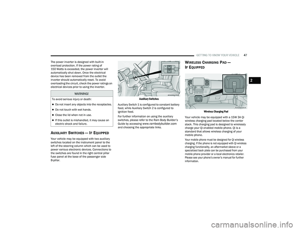
Your vehicle may be equipped with two auxiliary
switches located on the instrument panel to the
left of the steering column which can be used to
power various electronic devices. Connections to
the switches are found in the right central pillar
fuse panel at the base of the passenger side
B-pillar.
Auxiliary Switches
Auxiliary Switch 1 is configured to constant battery
feed, while Auxiliary Switch 2 is configured to
ignition feed.
For further information on using the auxiliary
switches, please refer to the Ram Body Builder’s
Guide by accessing
www.rambodybuilder.com
and choosing the appropriate links.
WIRELESS CHARGING PAD —
I
F EQUIPPED
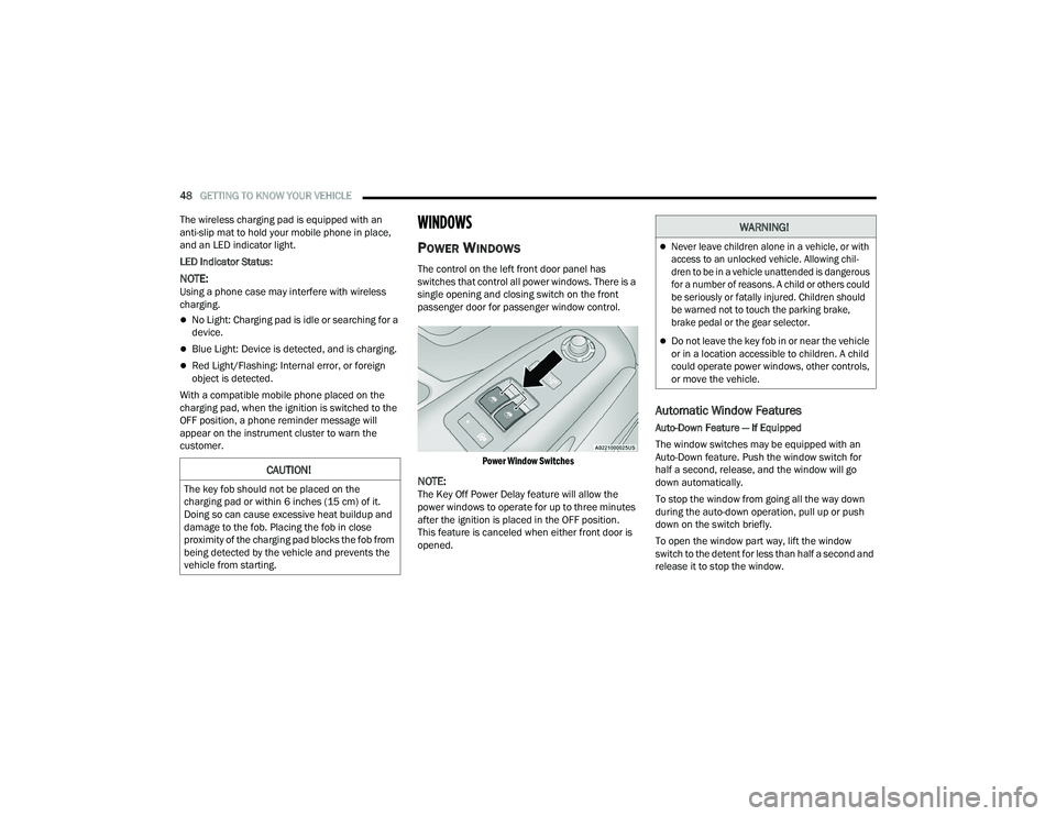
Wireless Charging Pad
Your vehicle may be equipped with a 15W 3A Qi
wireless charging pad located below the center
stack. This charging pad is designed to wirelessly
charge your Qi enabled mobile phone. Qi is a
standard that allows wireless charging of your
mobile phone.
Your mobile phone must be designed for Qi wireless
charging. If the phone is not equipped with Qi wireless
charging functionality, an aftermarket sleeve or a
specialized back plate can be purchased from your
mobile phone provider or a local electronics retailer.
Please see your phone’s owner’s manual for further
information.
WARNING!
To avoid serious injury or death:
Do not insert any objects into the receptacles.
Do not touch with wet hands.
Close the lid when not in use.
If this outlet is mishandled, it may cause an
electric shock and failure.
2
22_VF_OM_EN_USC_t.book Page 47
Page 50 of 268
48GETTING TO KNOW YOUR VEHICLE
The wireless charging pad is equipped with an
anti-slip mat to hold your mobile phone in place,
and an LED indicator light.
LED Indicator Status:
NOTE:Using a phone case may interfere with wireless
charging.
No Light: Charging pad is idle or searching for a
device.
Blue Light: Device is detected, and is charging.
Red Light/Flashing: Internal error, or foreign
object is detected.
With a compatible mobile phone placed on the
charging pad, when the ignition is switched to the
OFF position, a phone reminder message will
appear on the instrument cluster to warn the
customer.
WINDOWS
POWER WINDOWS
The control on the left front door panel has
switches that control all power windows. There is a
single opening and closing switch on the front
passenger door for passenger window control.
Power Window Switches
NOTE:The Key Off Power Delay feature will allow the
power windows to operate for up to three minutes
after the ignition is placed in the OFF position.
This feature is canceled when either front door is
opened.
Automatic Window Features
Auto-Down Feature — If Equipped
The window switches may be equipped with an
Auto-Down feature. Push the window switch for
half a second, release, and the window will go
down automatically.
To stop the window from going all the way down
during the auto-down operation, pull up or push
down on the switch briefly.
To open the window part way, lift the window
switch to the detent for less than half a second and
release it to stop the window.
CAUTION!
The key fob should not be placed on the
charging pad or within 6 inches (15 cm) of it.
Doing so can cause excessive heat buildup and
damage to the fob. Placing the fob in close
proximity of the charging pad blocks the fob from
being detected by the vehicle and prevents the
vehicle from starting.
WARNING!
Never leave children alone in a vehicle, or with
access to an unlocked vehicle. Allowing chil -
dren to be in a vehicle unattended is dangerous
for a number of reasons. A child or others could
be seriously or fatally injured. Children should
be warned not to touch the parking brake,
brake pedal or the gear selector.
Do not leave the key fob in or near the vehicle
or in a location accessible to children. A child
could operate power windows, other controls,
or move the vehicle.
22_VF_OM_EN_USC_t.book Page 48
Page 51 of 268
GETTING TO KNOW YOUR VEHICLE49
WINDOW BAR GRATES — IF EQUIPPED
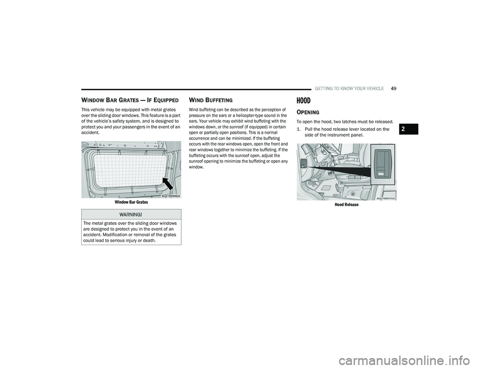
This vehicle may be equipped with metal grates
over the sliding door windows. This feature is a part
of the vehicle’s safety system, and is designed to
protect you and your passengers in the event of an
accident.
Window Bar Grates
WIND BUFFETING
Wind buffeting can be described as the perception of
pressure on the ears or a helicopter-type sound in the
ears. Your vehicle may exhibit wind buffeting with the
windows down, or the sunroof (if equipped) in certain
open or partially open positions. This is a normal
occurrence and can be minimized. If the buffeting
occurs with the rear windows open, open the front and
rear windows together to minimize the buffeting. If the
buffeting occurs with the sunroof open, adjust the
sunroof opening to minimize the buffeting or open any
window.
HOOD
OPENING
To open the hood, two latches must be released.
1. Pull the hood release lever located on the side of the instrument panel.
Hood Release
WARNING!
The metal grates over the sliding door windows
are designed to protect you in the event of an
accident. Modification or removal of the grates
could lead to serious injury or death.
2
22_VF_OM_EN_USC_t.book Page 49
Page 52 of 268
50GETTING TO KNOW YOUR VEHICLE
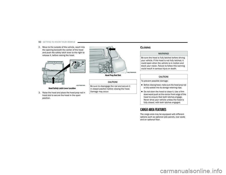
2. Move to the outside of the vehicle, reach into the opening beneath the center of the hood
and push the safety latch lever to the right to
release it, before raising the hood.
Hood Safety Latch Lever Location
3. Raise the hood and place the hood prop rod in hood slot to secure the hood in the open
position.
Hood Prop Rod Slot
CLOSING
CARGO AREA FEATURES
The cargo area may be equipped with different
options such as optional side panels, rear seats
and an optional floor.
CAUTION!
Be sure to disengage the rod and secure it
in closed position before closing the hood.
Damage may occur.
WARNING!
Be sure the hood is fully latched before driving
your vehicle. If the hood is not fully latched, it
could open when the vehicle is in motion and
block your vision. Failure to follow this warning
could result in serious injury or death.
CAUTION!
To prevent possible damage:
Before closing hood, make sure the hood prop rod
is fully seated into its storage retaining clips.
Do not slam the hood to close it. Use a firm
downward push at the center front edge of the
hood to ensure that both latches engage.
Never drive your vehicle unless the hood is
fully closed, with both latches engaged.
22_VF_OM_EN_USC_t.book Page 50
Page 54 of 268
52GETTING TO KNOW YOUR INSTRUMENT PANEL
BASE / MIDLINE INSTRUMENT CLUSTER
D
ESCRIPTIONS
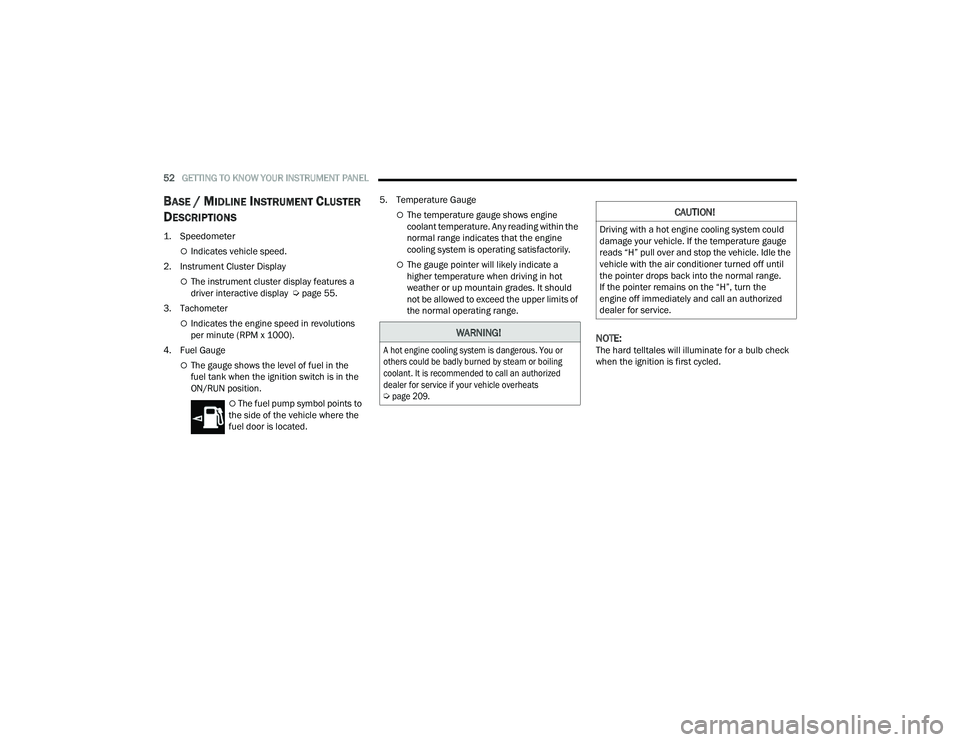
1. Speedometer
Indicates vehicle speed.
2. Instrument Cluster Display
The instrument cluster display features a
driver interactive display Ú page 55.
3. Tachometer
Indicates the engine speed in revolutions
per minute (RPM x 1000).
4. Fuel Gauge
The gauge shows the level of fuel in the
fuel tank when the ignition switch is in the
ON/RUN position.
The fuel pump symbol points to
the side of the vehicle where the
fuel door is located. 5. Temperature Gauge
The temperature gauge shows engine
coolant temperature. Any reading within the
normal range indicates that the engine
cooling system is operating satisfactorily.
The gauge pointer will likely indicate a
higher temperature when driving in hot
weather or up mountain grades. It should
not be allowed to exceed the upper limits of
the normal operating range.
NOTE:The hard telltales will illuminate for a bulb check
when the ignition is first cycled.
WARNING!
A hot engine cooling system is dangerous. You or
others could be badly burned by steam or boiling
coolant. It is recommended to call an authorized
dealer for service if your vehicle overheats
Ú
page 209.
CAUTION!
Driving with a hot engine cooling system could
damage your vehicle. If the temperature gauge
reads “H” pull over and stop the vehicle. Idle the
vehicle with the air conditioner turned off until
the pointer drops back into the normal range.
If the pointer remains on the “H”, turn the
engine off immediately and call an authorized
dealer for service.
22_VF_OM_EN_USC_t.book Page 52