ignition RAM PROMASTER 2023 Owner's Manual
[x] Cancel search | Manufacturer: RAM, Model Year: 2023, Model line: PROMASTER, Model: RAM PROMASTER 2023Pages: 296, PDF Size: 12.31 MB
Page 49 of 296

GETTING TO KNOW YOUR VEHICLE47
POWER INVERTER — IF EQUIPPED
There is a 115 Volt, 150 Watt inverter outlet
located on the instrument panel, to the right of
the radio, to convert DC current to AC current.
This outlet can power cellular phones, electronics
and other low power devices requiring power up to
150 Watts. Certain game consoles will exceed this
power limit, as will most power tools.
Power Inverter Location
To turn on the power inverter outlet, simply plug in
the device. The outlet automatically turns off when
the device is unplugged.
The power inverter is designed with built-in overload
protection. If the power rating of 150 Watts is
exceeded, the power inverter will automatically shut
down. Once the electrical device has been removed
from the outlet the inverter should automatically reset.
To avoid overloading the circuit, check the power
ratings on electrical devices prior to using the inverter.
AUXILIARY SWITCHES — IF EQUIPPED
Your vehicle may be equipped with two auxiliary
switches located on the instrument panel to the
left of the steering column which can be used to
power various electronic devices. Connections to
the switches are found in the right central pillar
fuse panel at the base of the passenger side
B-pillar.
Auxiliary Switches
Auxiliary Switch 1 is configured to constant battery
feed, while Auxiliary Switch 2 is configured to
ignition feed.
For further information on using the auxiliary
switches, please refer to the Ram Body Builder’s
Guide by accessing
www.rambodybuilder.com
and choosing the appropriate links.
After the use of high power draw accessories, or
long periods of the vehicle not being started (with
accessories still plugged in), the vehicle must be
driven a sufficient length of time to allow the
generator to recharge the vehicle's battery.
CAUTION!
WARNING!
To avoid serious injury or death:
Do not insert any objects into the receptacles.
Do not touch with wet hands.
Close the lid when not in use.
If this outlet is mishandled, it may cause an
electric shock and failure.
2
23_VF_OM_EN_USC_t.book Page 47
Page 50 of 296
48GETTING TO KNOW YOUR VEHICLE
WIRELESS CHARGING PAD —
I
F EQUIPPED
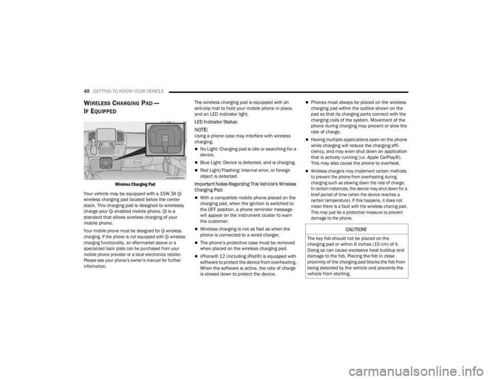
Wireless Charging Pad
Your vehicle may be equipped with a 15W 3A Qi
wireless charging pad located below the center
stack. This charging pad is designed to wirelessly
charge your Qi enabled mobile phone. Qi is a
standard that allows wireless charging of your
mobile phone.
Your mobile phone must be designed for Qi wireless
charging. If the phone is not equipped with Qi wireless
charging functionality, an aftermarket sleeve or a
specialized back plate can be purchased from your
mobile phone provider or a local electronics retailer.
Please see your phone’s owner’s manual for further
information.
The wireless charging pad is equipped with an
anti-slip mat to hold your mobile phone in place,
and an LED indicator light.
LED Indicator Status:
NOTE:Using a phone case may interfere with wireless
charging.
No Light: Charging pad is idle or searching for a
device.
Blue Light: Device is detected, and is charging.
Red Light/Flashing: Internal error, or foreign
object is detected.
Important Notes Regarding This Vehicle’s Wireless
Charging Pad:
With a compatible mobile phone placed on the
charging pad, when the ignition is switched to
the OFF position, a phone reminder message
will appear on the instrument cluster to warn
the customer.
Wireless charging is not as fast as when the
phone is connected to a wired charger.
The phone’s protective case must be removed
when placed on the wireless charging pad.
iPhone® 12 (including iPod®) is equipped with
software to protect the device from overheating.
When the software is active, the rate of charge
is slowed down to protect the device.
Phones must always be placed on the wireless
charging pad within the outline shown on the
pad so that its charging parts connect with the
charging coils of the system. Movement of the
phone during charging may prevent or slow the
rate of charge.
Having multiple applications open on the phone
while charging will reduce the charging effi -
ciency, and may even shut down an application
that is actively running (i.e. Apple CarPlay®).
This may also cause the phone to overheat.
Wireless chargers may implement certain methods
to prevent the phone from overheating during
charging such as slowing down the rate of charge.
In certain instances, the device may shut down for a
brief period of time (when the device reaches a
certain temperature). If this happens, it does not
mean there is a fault with the wireless charing pad.
This may just be a protective measure to prevent
damage to the phone.
CAUTION!
The key fob should not be placed on the
charging pad or within 6 inches (15 cm) of it.
Doing so can cause excessive heat buildup and
damage to the fob. Placing the fob in close
proximity of the charging pad blocks the fob from
being detected by the vehicle and prevents the
vehicle from starting.
23_VF_OM_EN_USC_t.book Page 48
Page 51 of 296

GETTING TO KNOW YOUR VEHICLE49
WINDOWS
POWER WINDOWS
The control on the left front door panel has
switches that control all power windows. There is a
single opening and closing switch on the front
passenger door for passenger window control.
Power Window Switches
NOTE:The Key Off Power Delay feature will allow the
power windows to operate for up to three minutes
after the ignition is placed in the OFF position.
This feature is canceled when either front door is
opened.
Automatic Window Features — If Equipped
Auto-Down Feature
The window switches may be equipped with an
Auto-Down feature. Push the window switch for
half a second, release, and the window will go
down automatically.
To stop the window from going all the way down
during the auto-down operation, pull up or push
down on the switch briefly. To open the window part way, lift the window
switch to the detent for less than half a second and
release it to stop the window.
WINDOW BAR GRATES — IF EQUIPPED
This vehicle may be equipped with metal grates
over the sliding door windows. This feature is a part
of the vehicle’s safety system, and is designed to
protect you and your passengers in the event of an
accident.
Window Bar Grates
WARNING!
Never leave children alone in a vehicle, or with
access to an unlocked vehicle. Allowing children to
be in a vehicle unattended is dangerous for a
number of reasons. A child or others could be seri -
ously or fatally injured. Children should be warned
not to touch the parking brake, brake pedal or the
gear selector.
Do not leave the key fob in or near the vehicle
or in a location accessible to children, and do
not leave the Keyless Enter ‘n Go™ Ignition in
the ON/RUN position. Occupants, particularly
unattended children, can become entrapped
by the windows while operating the power
window switches. Such entrapment may
result in serious injury or death.
WARNING!
There is no auto-reverse protection. Be sure to
clear all objects from the window before closing.2
23_VF_OM_EN_USC_t.book Page 49
Page 55 of 296
GETTING TO KNOW YOUR INSTRUMENT PANEL53
Use this QR code to access your
digital experience.
BASE / MIDLINE INSTRUMENT CLUSTER
D
ESCRIPTIONS
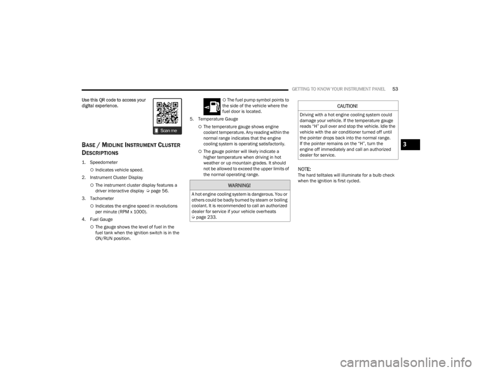
1. Speedometer
Indicates vehicle speed.
2. Instrument Cluster Display
The instrument cluster display features a
driver interactive display Ú page 56.
3. Tachometer
Indicates the engine speed in revolutions
per minute (RPM x 1000).
4. Fuel Gauge
The gauge shows the level of fuel in the
fuel tank when the ignition switch is in the
ON/RUN position.
The fuel pump symbol points to
the side of the vehicle where the
fuel door is located.
5. Temperature Gauge
The temperature gauge shows engine
coolant temperature. Any reading within the
normal range indicates that the engine
cooling system is operating satisfactorily.
The gauge pointer will likely indicate a
higher temperature when driving in hot
weather or up mountain grades. It should
not be allowed to exceed the upper limits of
the normal operating range.
NOTE:The hard telltales will illuminate for a bulb check
when the ignition is first cycled.
WARNING!
A hot engine cooling system is dangerous. You or
others could be badly burned by steam or boiling
coolant. It is recommended to call an authorized
dealer for service if your vehicle overheats
Ú page 233.
CAUTION!
Driving with a hot engine cooling system could
damage your vehicle. If the temperature gauge
reads “H” pull over and stop the vehicle. Idle the
vehicle with the air conditioner turned off until
the pointer drops back into the normal range.
If the pointer remains on the “H”, turn the
engine off immediately and call an authorized
dealer for service.
3
23_VF_OM_EN_USC_t.book Page 53
Page 57 of 296
GETTING TO KNOW YOUR INSTRUMENT PANEL55
INSTRUMENT CLUSTER DESCRIPTIONS
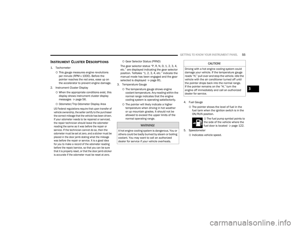
1. Tachometer
This gauge measures engine revolutions
per minute (RPM x 1000). Before the
pointer reaches the red area, ease up on
the accelerator to prevent engine damage.
2. Instrument Cluster Display
When the appropriate conditions exist, this
display shows instrument cluster display
messages Ú page 56.
Odometer/Trip Odometer Display Area
US Federal regulations require that upon transfer of
vehicle ownership, the seller certify to the purchaser
the correct mileage that the vehicle has been driven.
If your odometer needs to be repaired or serviced,
the repair technician should leave the odometer
reading the same as it was before the repair or
service. If the technician cannot do so, then the
odometer must be set at zero, and a sticker must be
placed in the door jamb stating what the mileage
was before the repair or service. It is a good idea
for you to make a record of the odometer reading
before the repair/service, so that you can be sure
that it is properly reset, or that the door jamb sticker
is accurate if the odometer must be reset at zero.
Gear Selector Status (PRND)
The gear selector status “P, R, N, D, 1, 2, 3, 4,
etc.” are displayed indicating the gear selector
position. Telltales “1, 2, 3, 4, etc.” indicate the
manual mode has been engaged and the gear
selected is displayed Ú page 81.
3. Temperature Gauge
The temperature gauge shows engine
coolant temperature. Any reading within the
normal range indicates that the engine
cooling system is operating satisfactorily.
The pointer will likely indicate a higher
temperature when driving in hot weather
or up mountain grades. It should not be
allowed to exceed the upper limits of the
normal operating range. 4. Fuel GaugeThe pointer shows the level of fuel in the
fuel tank when the ignition switch is in the
ON/RUN position.
The fuel pump symbol points to
the side of the vehicle where the
fuel door is located Ú page 122.
5. Speedometer
Indicates vehicle speed.
WARNING!
A hot engine cooling system is dangerous. You or
others could be badly burned by steam or boiling
coolant. You may want to call an authorized
dealer for service if your vehicle overheats.
CAUTION!
Driving with a hot engine cooling system could
damage your vehicle. If the temperature gauge
reads “H,” pull over and stop the vehicle. Idle the
vehicle with the air conditioner turned off until
the pointer drops back into the normal range.
If the pointer remains on the “H,” turn the
engine off immediately and call an authorized
dealer for service.
3
23_VF_OM_EN_USC_t.book Page 55
Page 58 of 296
56GETTING TO KNOW YOUR INSTRUMENT PANEL
INSTRUMENT CLUSTER DISPLAY
Your vehicle will be equipped with an instrument
cluster display, which offers useful information
to the driver. With the ignition in the OFF mode,
opening/closing of a door will activate the display
for viewing, and display the total miles, or
kilometers, in the odometer. Your instrument
cluster display is designed to display important
information about your vehicle’s systems and
features. Using a driver interactive display located
on the instrument panel, your instrument cluster
display can show you how systems are working and
give you warnings when they are not. The steering
wheel mounted controls allow you to scroll through
the main menus and submenus. You can access
the specific information you want and make
selections and adjustments.
LOCATION AND CONTROLS
The instrument cluster display features a driver
interactive display that is located in the instrument
cluster.
Instrument Cluster Display and Controls
This system allows the driver to select a variety
of useful information by pushing the switches
mounted on the instrument panel. Examples of
menu items are:
Buzzer Volume
Exit Menu
If equipped with a Uconnect system, some
customer programmable features will display in
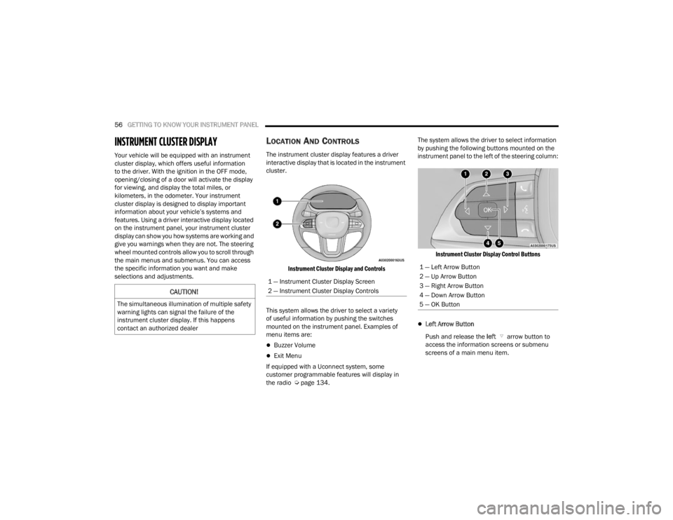
the radio Ú page 134. The system allows the driver to select information
by pushing the following buttons mounted on the
instrument panel to the left of the steering column:
Instrument Cluster Display Control Buttons
Left Arrow Button
Push and release the left arrow button to
access the information screens or submenu
screens of a main menu item.
CAUTION!
The simultaneous illumination of multiple safety
warning lights can signal the failure of the
instrument cluster display. If this happens
contact an authorized dealer
1 — Instrument Cluster Display Screen
2 — Instrument Cluster Display Controls
1 — Left Arrow Button
2 — Up Arrow Button
3 — Right Arrow Button
4 — Down Arrow Button
5 — OK Button
23_VF_OM_EN_USC_t.book Page 56
Page 59 of 296
GETTING TO KNOW YOUR INSTRUMENT PANEL57
Up Arrow Button
Push and release the up arrow button to
scroll upward through the main menu and
submenus.
Right Arrow Button
Push and release the right arrow button to
access the information screens or submenu
screens of a main menu item.
Down Arrow Button
Push and release the down arrow button to
scroll downward through the main menu and
submenus.
OK Button
Push the OK button to access/select the infor -
mation screens or submenu screens of a main
menu item. Push and hold the OK button for one
second to reset displayed/selected features
that can be reset.
NOTE:For vehicles with a 3.5 inch instrument cluster
display, press the OK button to toggle between
mph or km/h. For Screen Setup:
OK
button allows user to enter menu and
submenus.
Within each submenu layer, the up and
down arrow buttons will allow the user to
select the item of interest.
Pushing the OK button makes the selection and
a confirmation screen will appear (returning the
user to the first page of the submenu).
Pushing the left arrow button will exit each
submenu layer and return to the main menu.
Pushing the right arrow button will navigate
through each submenu layer.
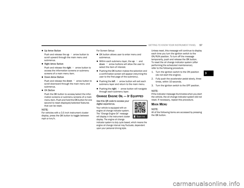
CHANGE ENGINE OIL — IF EQUIPPED
Use this QR code to access your
digital experience.
Your vehicle is equipped with an
engine oil change indicator system.
The “Change Engine Oil” message
will display in the instrument cluster
display. The engine oil change
indicator system is duty cycle based, which means the
engine oil change interval may fluctuate, dependent
upon your personal driving style.
Unless reset, this message will continue to display
each time you turn the ignition switch to the
ON/RUN position. To turn off the message
temporarily, push and release the
OK button.
To reset the oil change indicator system (after
performing the scheduled maintenance),
refer to the following procedure.
1. Turn the ignition switch to the ON position (do not start the engine).
2. Fully push the accelerator pedal slowly, three times, within 10 seconds.
3. Turn the ignition switch to the OFF position.
NOTE:If the indicator message illuminates when you start
the vehicle, the oil change indicator system did not
reset. If necessary, repeat this procedure.
MAIN MENU
NOTE:All of the following items are accessed by pressing
the OK button.
3
23_VF_OM_EN_USC_t.book Page 57
Page 65 of 296

GETTING TO KNOW YOUR INSTRUMENT PANEL63
Security – If Equipped
By selecting the item “Security” you can make the following adjustments:
Passenger Airbag: Front passenger air bag may be enabled or disabled
Speed Warning: Set the vehicle speed limit, which the driver is notified through a visual and acoustic signaling (display of a message and a symbol on the
display)
Seat Belt Reminder: This function is only viewable when the Seat Belt Reminder (SBR) system is active
Hill Start Assist: Activation/Deactivation of the Hill Start Assist system Vehicle Shut Off
——
By selecting the item “Vehicle Shut Off”,
you can turn off the engine from the
instrument cluster. This feature is
available in the event of a Keyless
Ignition system failure, and will display
instructions for turning off the engine via
the instrument cluster display controls.
*If Equipped
3
23_VF_OM_EN_USC_t.book Page 63
Page 67 of 296

GETTING TO KNOW YOUR INSTRUMENT PANEL65
Security – If Equipped
By selecting the item “Security” you can make the
following adjustments (if equipped):
Passenger Airbag: Front passenger air bag may
be enabled or disabled
Speed Warning: Set the vehicle speed limit,
which the driver is notified through a visual and
acoustic signaling (display of a message and a
symbol on the display)
Seat Belt Reminder: This function is only view -
able when the Seat Belt Reminder (SBR) system
is active
Hill Start Assist: Activation/Deactivation of the
Hill Start Assist system
WARNING LIGHTS AND MESSAGES
The warning/indicator lights will illuminate in the
instrument panel together with a dedicated message
and/or acoustic signal when applicable. These
indications are indicative and precautionary and as
such must not be considered as exhaustive and/or
alternative to the information contained in the Owner’s
Manual, which you are advised to read carefully in all
cases. Always refer to the information in this chapter in
the event of a failure indication. All active telltales will
display first if applicable. The system check menu may
appear different based upon equipment options and
current vehicle status. Some telltales are optional and
may not appear.
RED WARNING LIGHTS
Air Bag Warning Light
This light will turn on for four to eight seconds
as a bulb check when the ignition is placed in
the ON/RUN or MAR/ON/RUN position. If the
light is either not on during startup, stays on,
or turns on while driving, have the system inspected at
an authorized dealer as soon as possible. This light will
illuminate with a single chime when a fault with the
Air Bag Warning Light has been detected, it will stay
on until the fault is cleared. If the light comes on
intermittently or remains on while driving, have an
authorized dealer service the vehicle immediately.
Safety & Assitance
Warning Buzzer Volume
—Off, Low, Medium, High
Backup Alarm —On / Off
Vehicle Shut Off ——By selecting the item “Vehicle Shut
Off”, you can turn off the engine from
the instrument cluster. This feature is
available in the event of a Keyless
Ignition system failure, and will
display instructions for turning off the
engine via the instrument cluster
display controls.
*If Equipped
3
23_VF_OM_EN_USC_t.book Page 65
Page 68 of 296
66GETTING TO KNOW YOUR INSTRUMENT PANEL
Brake Warning Light
This warning light monitors various brake
functions, including brake fluid level and
parking brake application. If the brake
light turns on it may indicate that the
parking brake is applied, that the brake fluid level
is low, or that there is a problem with the Anti-Lock
Brake System reservoir.
If the light remains on when the parking brake has been
disengaged, and the fluid level is at the full mark on the
master cylinder reservoir, it indicates a possible brake
hydraulic system malfunction or that a problem with the
Brake Booster has been detected by the Anti-Lock
Brake System (ABS) / Electronic Stability Control (ESC)
system. In this case, the light will remain on until the
condition has been corrected. If the problem is related
to the brake booster, the ABS pump will run when
applying the brake, and a brake pedal pulsation may be
felt during each stop.
The dual brake system provides a reserve braking
capacity in the event of a failure to a portion of the
hydraulic system. A leak in either half of the dual
brake system is indicated by the Brake Warning
Light, which will turn on when the brake fluid
level in the master cylinder has dropped below a
specified level.
The light will remain on until the cause is corrected.
NOTE:The light may flash momentarily during sharp
cornering maneuvers, which change fluid level
conditions. The vehicle should have service
performed, and the brake fluid level checked.
If brake failure is indicated, immediate repair is
necessary.
Vehicles equipped with the Anti-Lock Brake System
(ABS) are also equipped with Electronic Brake
Force Distribution (EBD). In the event of an EBD
failure, the Brake Warning Light will turn on along
with the ABS Light. Immediate repair to the ABS
system is required.
Operation of the Brake Warning Light can be
checked by turning the ignition switch from the OFF
position to the ON/RUN position. The light should
illuminate for approximately two seconds. The light
should then turn off unless the parking brake is
applied or a brake fault is detected. If the light does
not illuminate, have the light inspected by an
authorized dealer. The light also will turn on when the parking brake
is applied with the ignition switch in the ON/RUN
position.
NOTE:This light shows only that the parking brake is
applied. It does not show the degree of brake
application.
Battery Charge Warning Light
This warning light will illuminate when the
battery is not charging properly. If it stays on
while the engine is running, there may be
a malfunction with the charging system.
Contact an authorized dealer as soon as possible.
This indicates a possible problem with the
electrical system or a related component.
Door Open Warning Light
This indicator will illuminate when one or
more door(s) are not fully closed. A pop-up
appears on the instrument cluster display
showing which door is open.
NOTE:If the vehicle is moving and a door is opened, there
will also be a single chime.
WARNING!
Driving a vehicle with the red brake light on is
dangerous. Part of the brake system may have
failed. It will take longer to stop the vehicle.
You could have a collision. Have the vehicle
checked immediately.
23_VF_OM_EN_USC_t.book Page 66