warning lights RAM PROMASTER 2023 Owner's Manual
[x] Cancel search | Manufacturer: RAM, Model Year: 2023, Model line: PROMASTER, Model: RAM PROMASTER 2023Pages: 296, PDF Size: 12.31 MB
Page 140 of 296
138MULTIMEDIA
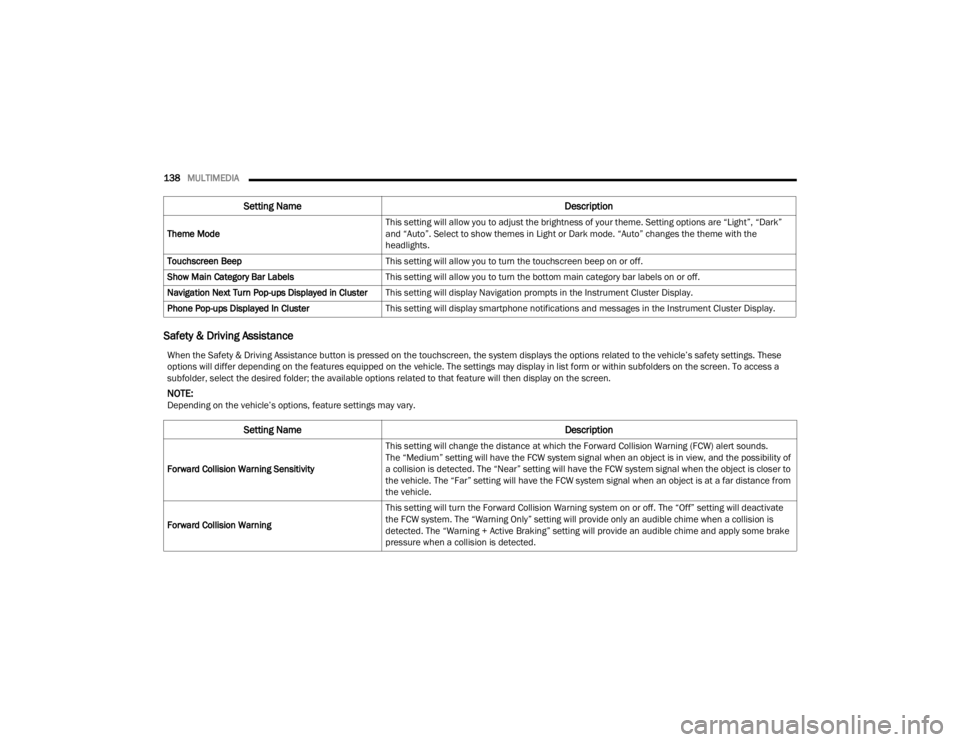
Safety & Driving Assistance
Theme Mode This setting will allow you to adjust the brightness of your theme. Setting options are “Light”, “Dark”
and “Auto”. Select to show themes in Light or Dark mode. “Auto” changes the theme with the
headlights.
Touchscreen Beep This setting will allow you to turn the touchscreen beep on or off.
Show Main Category Bar Labels This setting will allow you to turn the bottom main category bar labels on or off.
Navigation Next Turn Pop-ups Displayed in Cluster This setting will display Navigation prompts in the Instrument Cluster Display.
Phone Pop-ups Displayed In Cluster This setting will display smartphone notifications and messages in the Instrument Cluster Display.
Setting Name Description
When the Safety & Driving Assistance button is pressed on the touchscreen, the system displays the options related to the vehicle’s safety settings. These
options will differ depending on the features equipped on the vehicle. The settings may display in list form or within subfolders on the screen. To access a
subfolder, select the desired folder; the available options related to that feature will then display on the screen.
NOTE:Depending on the vehicle’s options, feature settings may vary.
Setting Name Description
Forward Collision Warning SensitivityThis setting will change the distance at which the Forward Collision Warning (FCW) alert sounds.
The “Medium” setting will have the FCW system signal when an object is in view, and the possibility of
a collision is detected. The “Near” setting will have the FCW system signal when the object is closer to
the vehicle. The “Far” setting will have the FCW system signal when an object is at a far distance from
the vehicle.
Forward Collision Warning This setting will turn the Forward Collision Warning system on or off. The “Off” setting will deactivate
the FCW system. The “Warning Only” setting will provide only an audible chime when a collision is
detected. The “Warning + Active Braking” setting will provide an audible chime and apply some brake
pressure when a collision is detected.
23_VF_OM_EN_USC_t.book Page 138
Page 141 of 296
MULTIMEDIA139
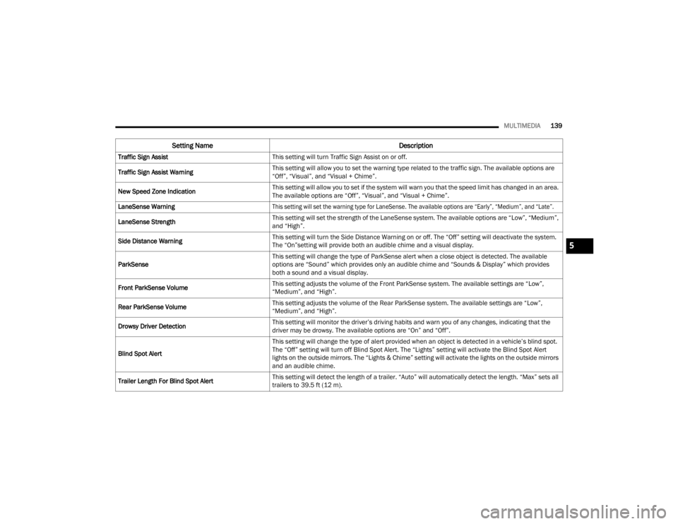
Traffic Sign Assist This setting will turn Traffic Sign Assist on or off.
Traffic Sign Assist Warning This setting will allow you to set the warning type related to the traffic sign. The available options are
“Off”, “Visual”, and “Visual + Chime”.
New Speed Zone Indication This setting will allow you to set if the system will warn you that the speed limit has changed in an area.
The available options are “Off”, “Visual”, and “Visual + Chime”.
LaneSense Warning
This setting will set the warning type for LaneSense. The available options are “Early”, “Medium”, and “Late”.
LaneSense Strength This setting will set the strength of the LaneSense system. The available options are “Low”, “Medium”,
and “High”.
Side Distance Warning This setting will turn the Side Distance Warning on or off. The “Off” setting will deactivate the system.
The “On”setting will provide both an audible chime and a visual display.
ParkSense This setting will change the type of ParkSense alert when a close object is detected. The available
options are “Sound” which provides only an audible chime and “Sounds & Display” which provides
both a sound and a visual display.
Front ParkSense Volume This setting adjusts the volume of the Front ParkSense system. The available settings are “Low”,
“Medium”, and “High”.
Rear ParkSense Volume This setting adjusts the volume of the Rear ParkSense system. The available settings are “Low”,
“Medium”, and “High”.
Drowsy Driver Detection This setting will monitor the driver’s driving habits and warn you of any changes, indicating that the
driver may be drowsy. The available options are “On” and “Off”.
Blind Spot Alert This setting will change the type of alert provided when an object is detected in a vehicle’s blind spot.
The “Off” setting will turn off Blind Spot Alert. The “Lights” setting will activate the Blind Spot Alert
lights on the outside mirrors. The “Lights & Chime” setting will activate the lights on the outside mirrors
and an audible chime.
Trailer Length For Blind Spot Alert This setting will detect the length of a trailer. “Auto” will automatically detect the length. “Max” sets all
trailers to 39.5 ft (12 m).
Setting Name
Description
5
23_VF_OM_EN_USC_t.book Page 139
Page 160 of 296
158SAFETY
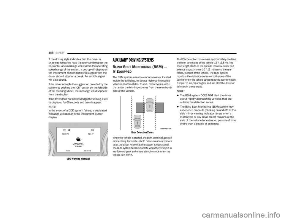
If the driving style indicates that the driver is
unable to follow the road trajectory and respect the
horizontal lane markings while within the operating
speed range of the system, a pop up will display on
the instrument cluster display to suggest that the
driver should stop for a break. An audible signal
will also sound.
If the driver accepts the suggestion provided by the
system by pushing the “OK” button on the left side
of the steering wheel, the message will disappear
from the display.
If the driver
does not acknowledge
the warning, it will
be displayed for 60 seconds and then disappear.
NOTE:In the event of a DDD system failure, a dedicated
message will appear in the instrument cluster
display.
DDD Warning Message
AUXILIARY DRIVING SYSTEMS
BLIND SPOT MONITORING (BS M) —
I
F EQUIPPED
The BSM system uses two radar sensors, located
inside the taillights, to detect highway licensable
vehicles (automobiles, trucks, motorcycles, etc.)
that enter the blind spot zones from the rear/front/
side of the vehicle.
Rear Detection Zones
When the vehicle is started, the BSM Warning Light will
momentarily illuminate in both outside rearview mirrors
to let the driver know that the system is operational.
The BSM system sensors operate when the vehicle is in
any forward gear and enters standby mode when the
vehicle is in PARK. The BSM detection zone covers approximately one lane
width on both sides of the vehicle 12 ft (3.8 m). The
zone length starts at the outside rearview mirror and
extends approximately 10 ft (3 m) beyond the rear
fascia/bumper of the vehicle. The BSM system
monitors the detection zones on both sides of the
vehicle when the vehicle speed reaches approximately
6 mph (10 km/h) or higher and will alert the driver of
vehicles in these areas.
NOTE:
The BSM system DOES NOT alert the driver
about rapidly approaching vehicles that are
outside the detection zones.
The Blind Spot Monitoring (BSM) system may
experience dropouts (blinking on and off) of the
side mirror warning indicator lamps when a
motorcycle or any small object remains at the
side of the vehicle for extended periods of time
(more than a couple of seconds).
23_VF_OM_EN_USC_t.book Page 158
Page 161 of 296

SAFETY159
The vehicle’s taillights, where the radar sensors
are located, must remain free of snow, ice, and
dirt/road contamination so that the BSM system
can function properly. Do not block the taillights
with foreign objects (bumper stickers, bicycle
racks, etc.).
Radar Sensor Locations
If the system detects degraded performance due
to contamination or foreign objects, a message will
warn you of a blocked sensor and the warning
indicators in the side view mirrors will be on.
The warning indicators will remain illuminated until
blockage clearing conditions are met. First clear
the taillights around the sensors of the blockage.
After removing the blockage, the following
procedure can be used to reset the system, cycle
the ignition from ON to OFF and then back ON. If the blockage message is still present after
cycling the ignition and driving in traffic, check
again for a blockage.
The BSM system notifies the driver of objects in the
detection zones by illuminating the BSM Warning
Light located in the outside mirrors in addition to
sounding an audible (chime) alert and reducing the
radio volume Ú
page 161.
Warning Light Location
The BSM system monitors the detection zone from
three different entry points (side, rear, front) while
driving to see if an alert is necessary. The BSM
system will issue an alert during these types of
zone entries.
Entering From The Side
Vehicles that move into your adjacent lanes from
either side of the vehicle.
Side Monitoring
Entering From The Rear
Vehicles that come up from behind your vehicle on
either side and enter the rear detection zone with
a relative speed of less than 30 mph (48 km/h).
Rear Monitoring
6
23_VF_OM_EN_USC_t.book Page 159
Page 163 of 296

SAFETY161
Rear Cross Path (RCP)
RCP is intended to aid the driver when backing out
of parking spaces where their vision of oncoming
vehicles may be blocked. Proceed slowly and
cautiously out of the parking space until the rear
end of the vehicle is exposed. The RCP system will
then have a clear view of the cross traffic, and if an
oncoming vehicle is detected, alert the driver.
RCP Detection Zones
RCP monitors the rear detection zones on both
sides of the vehicle, for objects that are moving
toward the side of the vehicle with a minimum
speed of approximately 3 mph (5 km/h), to objects
moving a maximum of approximately 20 mph
(32 km/h), such as in parking lot situations.
When RCP is on and the vehicle is in REVERSE (R),
the driver is alerted using both the visual and
audible alarms, including reducing the radio
volume.
NOTE:
In a parking lot situation, oncoming vehicles can be
blocked by vehicles parked on either side. If the
sensors are blocked by other structures or vehicles, the
system will not be able to alert the driver.
Blind Spot Modes
Blind Spot has three selectable modes of operation
that are available in the Uconnect system.
Blind Spot Alert Lights Only
When operating in Blind Spot Alert mode, the BSM
system will provide a visual alert in the appropriate side
view mirror based on a detected object. However, when
the system is operating in Rear Cross Path (RCP) mode,
the system will respond with both visual and audible
alerts when a detected object is present. Whenever an
audible alert is requested, the radio is muted.
Blind Spot Alert Lights/Chime
When operating in Blind Spot Alert Lights/Chime mode,
the BSM system will provide a visual alert in the
appropriate side view mirror based on a detected
object. If the turn signal is then activated, and it
corresponds to an alert present on that side of the
vehicle, an audible chime will also be sounded.
Whenever a turn signal and detected object are present
on the same side at the same time, both the visual and
audible alerts will be issued. In addition to the audible
alert the radio (if on) will also be muted.
NOTE:Whenever an audible alert is requested by the
BSM system, the radio is also muted.
When the system is in RCP, the system shall respond
with both visual and audible alerts when a detected
object is present. Whenever an audible alert is
requested, the radio is also muted. Turn/hazard signal
status is ignored; the RCP state always requests the
chime.
Blind Spot Alert Off
When the BSM system is turned off there will be no
visual or audible alerts from either the BSM or RCP
systems.
NOTE:The BSM system will store the current operating
mode when the vehicle is shut off. Each time the
vehicle is started the previously stored mode will
be recalled and used.
WARNING!
Rear Cross Path Detection (RCP) is not a backup
aid system. It is intended to be used to help a
driver detect an oncoming vehicle in a parking
lot situation. Drivers must be careful when
backing up, even when using RCP. Always check
carefully behind your vehicle, look behind you,
and be sure to check for pedestrians, animals,
other vehicles, obstructions, and blind spots
before backing up. Failure to do so can result in
serious injury or death.
6
23_VF_OM_EN_USC_t.book Page 161
Page 185 of 296

SAFETY183
Air Bag System Components
NOTE:The Occupant Restraint Controller (ORC) monitors
the internal circuits and interconnecting wiring
associated with electrical Air Bag System Compo -
nents listed below:
Occupant Restraint Controller (ORC)
Air Bag Warning Light
Steering Wheel and Column
Instrument Panel
Driver and Front Passenger Air Bags
Seat Belt Buckle Switch
Supplemental Side Air Bags
Front and Side Impact Sensors
Seat Belt Pretensioners
If A Deployment Occurs
The front air bags are designed to deflate
immediately after deployment.
NOTE:Front and/or side air bags will not deploy in all colli -
sions. This does not mean something is wrong with
the air bag system. If you do have a collision which deploys the air
bags, any or all of the following may occur:
The air bag material may sometimes cause abra
-
sions and/or skin reddening to the occupants as
the air bags deploy and unfold. The abrasions are
similar to friction rope burns or those you might get
sliding along a carpet or gymnasium floor. They are
not caused by contact with chemicals. They are not
permanent and normally heal quickly. However, if
you haven’t healed significantly within a few days,
or if you have any blistering, see your doctor
immediately.
As the air bags deflate, you may see some
smoke-like particles. The particles are a normal
by-product of the process that generates the
non-toxic gas used for air bag inflation. These
airborne particles may irritate the skin, eyes,
nose, or throat. If you have skin or eye irritation,
rinse the area with cool water. For nose or throat
irritation, move to fresh air. If the irritation
continues, see your doctor. If these particles
settle on your clothing, follow the garment
manufacturer’s instructions for cleaning.
Do not drive your vehicle after the air bags have
deployed. If you are involved in another collision,
the air bags will not be in place to protect you.
NOTE:
Air bag covers may not be obvious in the interior
trim, but they will open during air bag deployment.
After any collision, the vehicle should be taken
to an authorized dealer immediately.
Fuel Cut Off Switch
Your vehicle is equipped with a Fuel Cut Off switch.
In the event of an accident, if the communication
network remains intact, and the power remains
intact, depending on the nature of the event, the
Fuel Cut Off Switch may perform the following
functions:
Cut off fuel to the engine and turn off the
engine.
Flash hazard lights as long as the battery has
power or until the hazard light button is pressed.
The hazard lights can be deactivated by
pressing the hazard light button.
WARNING!
Deployed air bags and seat belt pretensioners
cannot protect you in another collision. Have the air
bags, seat belt pretensioners, and the seat belt
retractor assemblies replaced by an authorized
dealer immediately. Also, have the Occupant
Restraint Controller System serviced as well.
6
23_VF_OM_EN_USC_t.book Page 183
Page 186 of 296
184SAFETY
Turn on the interior lights, which remain on as
long as the battery has power.
Unlock the power door locks.
NOTE:After an accident, remember to cycle the ignition
to the STOP (OFF/LOCK) position and remove the
key from the ignition switch to avoid draining the
battery. Carefully check the vehicle for fuel leaks in
the engine compartment and on the ground near
the engine compartment and fuel tank before
resetting the system and starting the engine.
If there are no fuel leaks or damage to the vehicle
electrical devices (e.g. headlights) after an
accident, reset the Fuel Cut Off Switch by following
the procedure described below. If you have any
doubt, contact an authorized dealer.
Fuel Cut Off Switch Reset Procedure
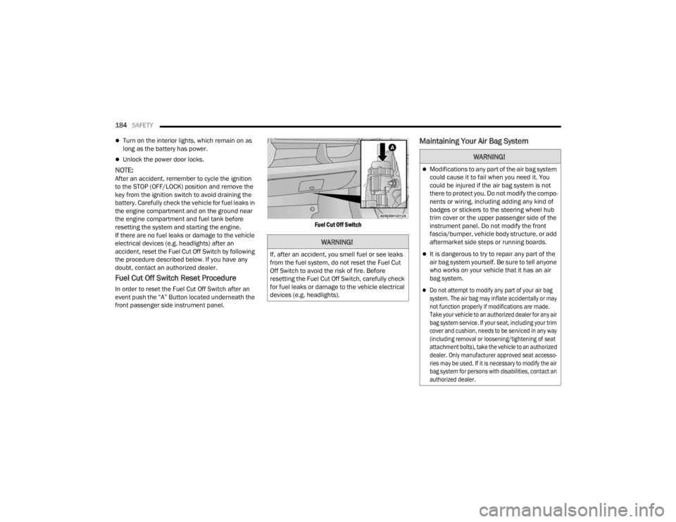
In order to reset the Fuel Cut Off Switch after an
event push the “A” Button located underneath the
front passenger side instrument panel.
Fuel Cut Off Switch
Maintaining Your Air Bag System
WARNING!
If, after an accident, you smell fuel or see leaks
from the fuel system, do not reset the Fuel Cut
Off Switch to avoid the risk of fire. Before
resetting the Fuel Cut Off Switch, carefully check
for fuel leaks or damage to the vehicle electrical
devices (e.g. headlights).
WARNING!
Modifications to any part of the air bag system
could cause it to fail when you need it. You
could be injured if the air bag system is not
there to protect you. Do not modify the compo
-
nents or wiring, including adding any kind of
badges or stickers to the steering wheel hub
trim cover or the upper passenger side of the
instrument panel. Do not modify the front
fascia/bumper, vehicle body structure, or add
aftermarket side steps or running boards.
It is dangerous to try to repair any part of the
air bag system yourself. Be sure to tell anyone
who works on your vehicle that it has an air
bag system.
Do not attempt to modify any part of your air bag
system. The air bag may inflate accidentally or may
not function properly if modifications are made.
Take your vehicle to an authorized dealer for any air
bag system service. If your seat, including your trim
cover and cushion, needs to be serviced in any way
(including removal or loosening/tightening of seat
attachment bolts), take the vehicle to an authorized
dealer. Only manufacturer approved seat accesso -
ries may be used. If it is necessary to modify the air
bag system for persons with disabilities, contact an
authorized dealer.
23_VF_OM_EN_USC_t.book Page 184
Page 193 of 296
SAFETY191
(Continued)
PERIODIC SAFETY CHECKS YOU SHOULD
M
AKE OUTSIDE THE VEHICLE
Tires
Examine tires for excessive tread wear and uneven
wear patterns. Check for stones, nails, glass, or
other objects lodged in the tread or sidewall.
Inspect the tread for cuts and cracks. Inspect
sidewalls for cuts, cracks, and bulges. Check the
lug nut/bolt torque for tightness. Check the tires
(including spare) for proper cold inflation pressure.
Lights
Have someone observe the operation of brake
lights and exterior lights while you work the
controls. Check turn signal and high beam
indicator lights on the instrument panel.
Door Latches
Check for proper closing, latching, and locking.
Fluid Leaks
Check area under the vehicle after overnight
parking for fuel, coolant, oil, or other fluid leaks.
Also, if gasoline fumes are detected or if fuel or
brake fluid leaks are suspected, the cause should
be located and corrected immediately.
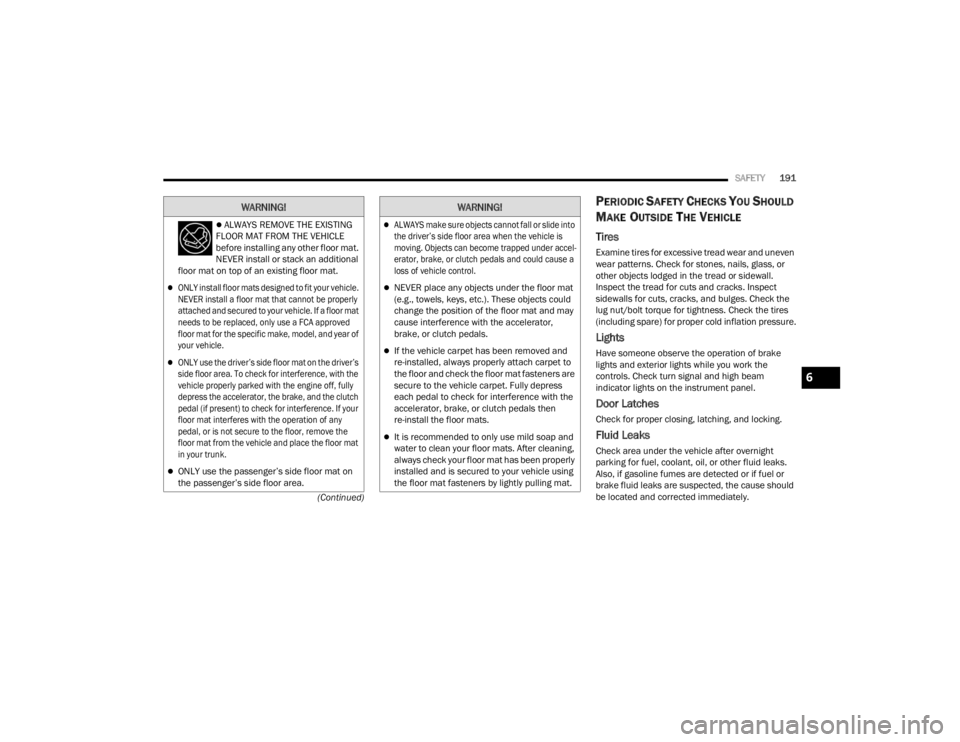
ALWAYS REMOVE THE EXISTING
FLOOR MAT FROM THE VEHICLE
before installing any other floor mat.
NEVER install or stack an additional
floor mat on top of an existing floor mat.
ONLY install floor mats designed to fit your vehicle.
NEVER install a floor mat that cannot be properly
attached and secured to your vehicle. If a floor mat
needs to be replaced, only use a FCA approved
floor mat for the specific make, model, and year of
your vehicle.
ONLY use the driver’s side floor mat on the driver’s
side floor area. To check for interference, with the
vehicle properly parked with the engine off, fully
depress the accelerator, the brake, and the clutch
pedal (if present) to check for interference. If your
floor mat interferes with the operation of any
pedal, or is not secure to the floor, remove the
floor mat from the vehicle and place the floor mat
in your trunk.
ONLY use the passenger’s side floor mat on
the passenger’s side floor area.
WARNING!
ALWAYS make sure objects cannot fall or slide into
the driver’s side floor area when the vehicle is
moving. Objects can become trapped under accel -
erator, brake, or clutch pedals and could cause a
loss of vehicle control.
NEVER place any objects under the floor mat
(e.g., towels, keys, etc.). These objects could
change the position of the floor mat and may
cause interference with the accelerator,
brake, or clutch pedals.
If the vehicle carpet has been removed and
re-installed, always properly attach carpet to
the floor and check the floor mat fasteners are
secure to the vehicle carpet. Fully depress
each pedal to check for interference with the
accelerator, brake, or clutch pedals then
re-install the floor mats.
It is recommended to only use mild soap and
water to clean your floor mats. After cleaning,
always check your floor mat has been properly
installed and is secured to your vehicle using
the floor mat fasteners by lightly pulling mat.
WARNING!
6
23_VF_OM_EN_USC_t.book Page 191
Page 196 of 296
194IN CASE OF EMERGENCY
(Continued)
SOS Call
1. Push the SOS Call button on the overhead
console.
NOTE:In case the SOS Call button is pushed in error,
there will be a ten second delay before the SOS
Call system initiates a call to a SOS operator.
To cancel the SOS Call connection, push the SOS
call button on the overhead console or press the
cancellation button on the Device Screen. Termi -
nation of the SOS Call will turn off the green LED
light on the overhead console.
2. The LED lights located within the SOS and ASSIST buttons on the overhead console
will turn green once a connection to a SOS
operator has been made.
3. Once a connection between the vehicle and a SOS operator is made, the SOS Call system
may transmit the following important vehicle
information to a SOS operator:
Indication that the occupant placed a
SOS Call
The vehicle brand
The last known GPS coordinates of the
vehicle
4. You should be able to speak with the SOS operator through the vehicle audio system to
determine if additional help is needed.
NOTE:
Your vehicle may be transmitting data as
authorized by the subscriber.
Once a connection is made between the
vehicle’s SOS Call system and the SOS oper -
ator, the SOS operator may be able to open
a voice connection with the vehicle to deter -
mine if additional help is needed. Once the
SOS operator opens a voice connection with
the vehicle’s SOS Call system, the operator
should be able to speak with you or other
vehicle occupants and hear sounds occur -
ring in the vehicle. The vehicle’s SOS Call
system will attempt to remain connected
with the SOS operator until the SOS oper -
ator terminates the connection. 5. The SOS operator may attempt to contact
appropriate emergency responders and
provide them with important vehicle
information and GPS coordinates.
WARNING!
ALWAYS obey traffic laws and pay attention to
the road. ALWAYS drive safely with your hands on
the steering wheel. You have full responsibility
and assume all risks related to the use of the
features and applications in this vehicle.
Only use the features and applications when it is
safe to do so. Failure to do so may result in an
accident involving serious injury or death.
WARNING!
If anyone in the vehicle could be in danger
(e.g., fire or smoke is visible, dangerous road
conditions or location), do not wait for voice
contact from an Emergency Services Agent. All
occupants should exit the vehicle immediately
and move to a safe location.
Never place anything on or near the vehicle’s
operable network and GPS antennas. You
could prevent operable network and GPS
signal reception, which can prevent your
vehicle from placing an emergency call.
An operable network and GPS signal reception
is required for the SOS Call system to function
properly.
23_VF_OM_EN_USC_t.book Page 194
Page 197 of 296
IN CASE OF EMERGENCY195
SOS Call System Limitations
Vehicles sold in Mexico DO NOT have SOS Call
system capabilities.
SOS or other emergency line operators in Mexico
may not answer or respond to SOS system calls. If the SOS Call system detects a malfunction,
any of the following may occur at the time the
malfunction is detected, and at the beginning of
each ignition cycle:
The overhead console lights located within the
SOS and ASSIST buttons will continuously illumi
-
nate red.
The Device Screen will display the following
message: “Vehicle device requires service.
Please contact an authorized dealer.”
An In-Vehicle Audio message will state “Vehicle
device requires service. Please contact an
authorized dealer.” Even if the SOS Call system is fully functional,
factors beyond FCA US LLC’s control may prevent
or stop the SOS Call system operation. These
include, but are not limited to, the following
factors:
The ignition is in the OFF position
The vehicle’s electrical systems are not intact
The SOS Call system software and/or hardware
are damaged during a crash
The vehicle battery loses power or becomes
disconnected during a vehicle crash
LTE (voice/data) or 4G (data) network and/or
Global Positioning Satellite signals are unavail
-
able or obstructed
Equipment malfunction at the SOS operator
facility
Operator error by the SOS operator
LTE (voice/data) or 4G (data) network congestion
Weather
Buildings, structures, geographic terrain, or
tunnels
The SOS Call system is embedded into the
vehicle’s electrical system. Do not add after -
market electrical equipment to the vehicle’s elec -
trical system. This may prevent your vehicle from
sending a signal to initiate an emergency call.
To avoid interference that can cause the SOS Call
system to fail, never add aftermarket equipment
(e.g., two-way mobile radio, CB radio, data
recorder, etc.) to your vehicle’s electrical system
or modify the antennas on your vehicle. IF YOUR
VEHICLE LOSES BATTERY POWER FOR ANY
REASON (INCLUDING DURING OR AFTER AN ACCI -
DENT), THE UCONNECT FEATURES, APPS AND
SERVICES, AMONG OTHERS, WILL NOT OPERATE.
Modifications to any part of the SOS Call
system could cause the air bag system to fail
when you need it. You could be injured if the
air bag system is not there to help protect you.
WARNING!
WARNING!
Ignoring the overhead console light could
mean you will not have SOS Call services.
If the overhead console light is illuminated,
have an authorized dealer service the SOS
Call system immediately.
The Occupant Restraint Control module turns
on the air bag Warning Light on the instrument
panel if a malfunction in any part of the
system is detected. If the Air Bag Warning
Light is illuminated, have an authorized dealer
service the Occupant Restraint Control system
immediately.
7
23_VF_OM_EN_USC_t.book Page 195