display RAM PROMASTER 2023 Manual Online
[x] Cancel search | Manufacturer: RAM, Model Year: 2023, Model line: PROMASTER, Model: RAM PROMASTER 2023Pages: 296, PDF Size: 12.31 MB
Page 151 of 296

MULTIMEDIA149
Software Updates
System Information
When the Software Updates button is pressed on the touchscreen, the system will display the setting related to updating the Uconnect software.
NOTE:Depending on the vehicle’s options, feature settings may vary.
Setting Name Description
Software Downloads over Wi-FiThis setting will allow software updates to happen over Wi-Fi. Selectable options for the setting are
“On” and “Off”.
After pressing the System Information button on the touchscreen, the following settings will be available:
NOTE:Depending on the vehicle’s options, feature settings may vary.
Setting Name
Description
Software LicenseWhen this feature is selected, a “Software License” screen will appear, displaying the system software
version.
Version Information When this feature is selected, a Version Information screen will appear, displaying information about
the version of your radio.
License Information When this feature is selected, a License Information screen will appear, displaying the licensing
information of your radio.
5
23_VF_OM_EN_USC_t.book Page 149
Page 152 of 296
150MULTIMEDIA
Reset
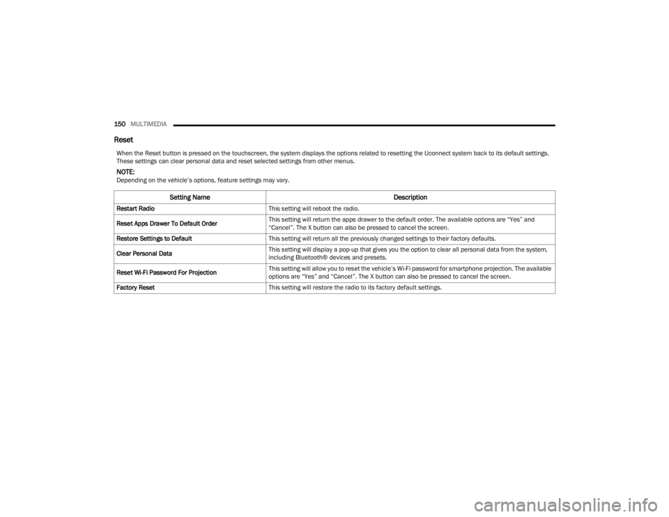
When the Reset button is pressed on the touchscreen, the system displays the options related to resetting the Uconnect system back to its default settings.
These settings can clear personal data and reset selected settings from other menus.
NOTE:Depending on the vehicle’s options, feature settings may vary.
Setting Name Description
Restart RadioThis setting will reboot the radio.
Reset Apps Drawer To Default Order This setting will return the apps drawer to the default order. The available options are “Yes” and
“Cancel”. The X button can also be pressed to cancel the screen.
Restore Settings to Default This setting will return all the previously changed settings to their factory defaults.
Clear Personal Data This setting will display a pop-up that gives you the option to clear all personal data from the system,
including Bluetooth® devices and presets.
Reset Wi-Fi Password For Projection This setting will allow you to reset the vehicle’s Wi-Fi password for smartphone projection. The available
options are “Yes” and “Cancel”. The X button can also be pressed to cancel the screen.
Factory Reset This setting will restore the radio to its factory default settings.
23_VF_OM_EN_USC_t.book Page 150
Page 160 of 296
158SAFETY
If the driving style indicates that the driver is
unable to follow the road trajectory and respect the
horizontal lane markings while within the operating
speed range of the system, a pop up will display on
the instrument cluster display to suggest that the
driver should stop for a break. An audible signal
will also sound.
If the driver accepts the suggestion provided by the
system by pushing the “OK” button on the left side
of the steering wheel, the message will disappear
from the display.
If the driver
does not acknowledge
the warning, it will
be displayed for 60 seconds and then disappear.
NOTE:In the event of a DDD system failure, a dedicated
message will appear in the instrument cluster
display.
DDD Warning Message
AUXILIARY DRIVING SYSTEMS
BLIND SPOT MONITORING (BS M) —
I
F EQUIPPED
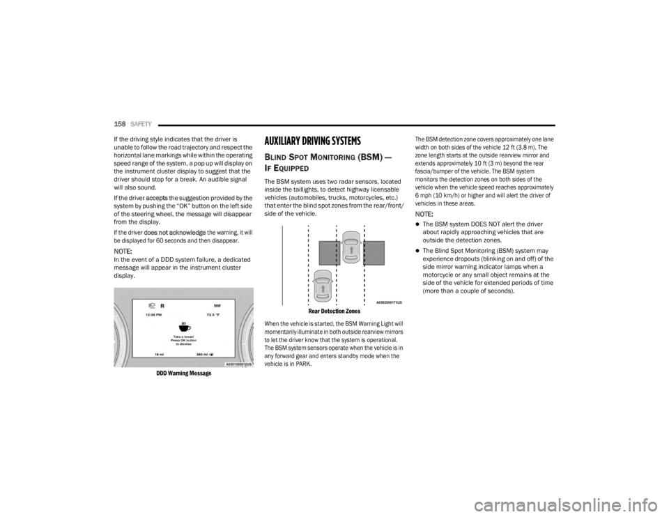
The BSM system uses two radar sensors, located
inside the taillights, to detect highway licensable
vehicles (automobiles, trucks, motorcycles, etc.)
that enter the blind spot zones from the rear/front/
side of the vehicle.
Rear Detection Zones
When the vehicle is started, the BSM Warning Light will
momentarily illuminate in both outside rearview mirrors
to let the driver know that the system is operational.
The BSM system sensors operate when the vehicle is in
any forward gear and enters standby mode when the
vehicle is in PARK. The BSM detection zone covers approximately one lane
width on both sides of the vehicle 12 ft (3.8 m). The
zone length starts at the outside rearview mirror and
extends approximately 10 ft (3 m) beyond the rear
fascia/bumper of the vehicle. The BSM system
monitors the detection zones on both sides of the
vehicle when the vehicle speed reaches approximately
6 mph (10 km/h) or higher and will alert the driver of
vehicles in these areas.
NOTE:
The BSM system DOES NOT alert the driver
about rapidly approaching vehicles that are
outside the detection zones.
The Blind Spot Monitoring (BSM) system may
experience dropouts (blinking on and off) of the
side mirror warning indicator lamps when a
motorcycle or any small object remains at the
side of the vehicle for extended periods of time
(more than a couple of seconds).
23_VF_OM_EN_USC_t.book Page 158
Page 164 of 296
162SAFETY
Trailer Merge Assist — If Equipped
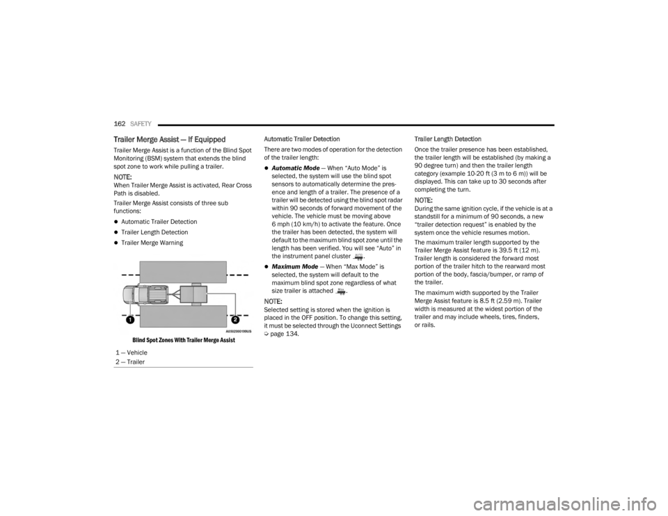
Trailer Merge Assist is a function of the Blind Spot
Monitoring (BSM) system that extends the blind
spot zone to work while pulling a trailer.
NOTE:When Trailer Merge Assist is activated, Rear Cross
Path is disabled.
Trailer Merge Assist consists of three sub
functions:
Automatic Trailer Detection
Trailer Length Detection
Trailer Merge Warning
Blind Spot Zones With Trailer Merge Assist
Automatic Trailer Detection
There are two modes of operation for the detection
of the trailer length:
Automatic Mode
— When “Auto Mode” is
selected, the system will use the blind spot
sensors to automatically determine the pres -
ence and length of a trailer. The presence of a
trailer will be detected using the blind spot radar
within 90 seconds of forward movement of the
vehicle. The vehicle must be moving above
6 mph (10 km/h) to activate the feature. Once
the trailer has been detected, the system will
default to the maximum blind spot zone until the
length has been verified. You will see “Auto” in
the instrument panel cluster .
Maximum Mode — When “Max Mode” is
selected, the system will default to the
maximum blind spot zone regardless of what
size trailer is attached .
NOTE:Selected setting is stored when the ignition is
placed in the OFF position. To change this setting,
it must be selected through the Uconnect Settings
Ú page 134. Trailer Length Detection
Once the trailer presence has been established,
the trailer length will be established (by making a
90 degree turn) and then the trailer length
category (example 10-20 ft (3 m to 6 m)) will be
displayed. This can take up to 30 seconds after
completing the turn.
NOTE:During the same ignition cycle, if the vehicle is at a
standstill for a minimum of 90 seconds, a new
“trailer detection request” is enabled by the
system once the vehicle resumes motion.
The maximum trailer length supported by the
Trailer Merge Assist feature is 39.5 ft (12 m).
Trailer length is considered the forward most
portion of the trailer hitch to the rearward most
portion of the body, fascia/bumper, or ramp of
the trailer.
The maximum width supported by the Trailer
Merge Assist feature is 8.5 ft (2.59 m). Trailer
width is measured at the widest portion of the
trailer and may include wheels, tires, finders,
or rails.
1 — Vehicle
2 — Trailer
23_VF_OM_EN_USC_t.book Page 162
Page 166 of 296

164SAFETY
FORWARD COLLISION WARNING (FCW)
W
ITH MITIGATION — IF EQUIPPED
The FCW with Mitigation system provides the driver
with audible warnings, visual warnings (within the
instrument cluster display), and may apply a brake
jerk to warn the driver when it detects a potential
frontal collision. The warnings and limited braking
are intended to provide the driver with enough time
to react, avoid or mitigate the potential collision.
NOTE:FCW monitors the information from the forward
looking camera as well as the Electronic Brake
Controller (EBC), to calculate the probability of a
forward collision. When the system determines
that a forward collision is probable, the driver will
be provided with audible and visual warnings as
well as a possible brake jerk warning.
If the driver does not take action based upon these
progressive warnings, then the system will provide
a limited level of active braking to help slow the
vehicle and mitigate the potential forward collision.
If the driver reacts to the warnings by braking and
the system determines that the driver intends to
avoid the collision by braking but has not applied
sufficient brake force, the system will compensate
and provide additional brake force as required.
If a FCW with Mitigation event begins at a speed below
26 mph (42 km/h), the system may provide the
maximum braking possible to mitigate the potential forward collision. Vehicles With Automatic Trans
-
mission: After the end of the intervention of automatic
braking, the transmission may remain in last gear
stored — therefore the vehicle could lurch forward, once
the brakes release a few seconds later. If the Forward
Collision Warning with Mitigation event stops the
vehicle completely, the system will hold the vehicle at
standstill for two seconds and then release the brakes.
FCW Message
When the system determines a collision with the
vehicle in front of you is no longer probable, the
warning message will be deactivated.
NOTE:
The minimum speed for FCW activation is
3 mph (5 km/h).
The FCW alerts may be triggered on objects
other than vehicles such as guardrails or sign
posts based on the course prediction. This is expected and is a part of normal FCW activation
and functionality.
It is unsafe to test the FCW system. To prevent
such misuse of the system the Active Braking
portion of FCW will be deactivated for the first
20 seconds from braking actuation.
The FCW system is intended for on-road use
only. If the vehicle is taken off-road, the FCW
system should be deactivated to prevent unnec
-
essary warnings to the surroundings.
FCW may not react to irrelevant objects such as
overhead objects, ground reflections, objects
not in the path of the vehicle, stationary objects
that are far away, oncoming traffic, or leading
vehicles with the same or higher rate of speed.
FCW will be disabled with the unavailable
screens Ú page 280.
WARNING!
Forward Collision Warning (FCW) is not intended
to avoid a collision on its own, nor can FCW
detect every type of potential collision. The driver
has the responsibility to avoid a collision by
controlling the vehicle via braking and steering.
Failure to follow this warning could lead to
serious injury or death.
23_VF_OM_EN_USC_t.book Page 164
Page 167 of 296

SAFETY165
Turning FCW On Or Off
The FCW button is located in the Uconnect display
in the control settings Ú page 134.
To turn the FCW system on, press the forward
collision button once.
To turn the FCW system off, press the forward
collision button once.
NOTE:
Changing the FCW status to “Off” deactivates
the system, so no warning or active braking will
be available in case of a possible collision.
Changing the FCW status to “Only Warning”
prevents the system from providing limited
active braking, or additional brake support if the
driver is not braking adequately in the event of
a potential frontal collision, but maintains the
audible and visual warnings.
When FCW status is set to “Warning and
Braking”, this allows the system to warn the
driver of a possible collision with the vehicle
in front using audible/visual warnings and it
applies autonomous braking.
The FCW system state is kept in memory from
one ignition position to the next. If the system is
turned off, it will maintain its status in the next
key cycle.
FCW Braking Status And Sensitivity
The FCW Sensitivity and Active Braking status are
programmable through the Uconnect system
Úpage 134.
Far
When the sensitivity of FCW is set to the
“Far” setting and the system status is
“Only Warning”, this allows the system to
warn the driver of a possible more distant
collision with the vehicle in front using
audible/visual warnings.
More cautious drivers that do not mind
frequent warnings may prefer this setting.
NOTE:The “Far” setting may result in a greater number of
FCW possible collision warnings experienced.
Medium
When the sensitivity of FCW is set to the
“Medium” setting and the system status is
“Only Warning”, this allows the system to
warn the driver of a possible collision with
the vehicle in front using audible/visual
warnings.
Near
When the sensitivity of FCW is set to the
“Near” setting and the system status is
“Only Warning”, this allows the system to warn the driver of a possible closer collision
with the vehicle in front using audible/
visual warnings.
This setting provides less reaction time than the
“Far” and “Medium” settings, which allows for a
more dynamic driving experience.
More dynamic or aggressive drivers that
want to avoid frequent warnings may prefer
this setting.
NOTE:The “Near” setting may result in a lesser number of
FCW possible collision warnings experienced.
FCW Limited Warning
If the instrument cluster displays “FCW Limited
Functionality Clean Front Windshield” momentarily,
there may be a condition that limits FCW functionality.
Although the vehicle is still drivable under normal
conditions, the active braking may not be fully
available. Once the condition that limited the system
performance is no longer present, the system will
return to its full performance state. If the problem
persists, see an authorized dealer.
If the front camera is blocked due to external
environmental conditions (i.e. heavy rain, snow,
fog), the system will be deactivated and a warning
message will display in the instrument cluster.6
23_VF_OM_EN_USC_t.book Page 165
Page 168 of 296

166SAFETY
Service FCW Warning
If the system turns off, and the instrument cluster
displays: “FCW Unavailable Service Required”,
this indicates there is an internal system fault.
Although the vehicle is still drivable under normal
conditions, have the system checked by an
authorized dealer.
The “FCW Temporarily Unavailable” message can
sometimes be displayed while driving in highly
reflective areas (i.e. tunnels with reflective tiles, or
ice and snow). The system will recover after the
vehicle has left these areas. Under rare conditions,
when the camera is not tracking any vehicles or
objects in its path, this warning may temporarily
occur. If weather conditions are not a factor, the
driver should examine the fascia/bumper where
the camera is located. It may require cleaning or
removal of an obstruction from the fascia/bumper
cover.
The FCW Warning Light will appear on the
instrument cluster to indicate the front camera
is obstructed by sun or other visibility reducing
weather.
NOTE:
If the “FCW Temporarily Unavailable” message
occurs frequently (e.g. more than once on every
trip) without any snow, rain, mud, or other
obstruction, have the camera realigned at an
authorized dealer.
Installing a snow plow or front-end protector is
not recommended. Doing so may block the
camera and inhibit FCW operation.
Use only a soft cloth for cleaning. Do not use
solvents or abrasive pastes.
Precautions While Driving With FCW
In certain driving conditions, such as:
Driving in the vicinity of a curve
Small vehicles and/or not aligned to the lane
Lane changing of other vehicles
Passing of vehicles in an oncoming intersection
The intervention of the system could be
unexpected or delayed. The driver must therefore
always pay particular attention, while maintaining
control of the vehicle to drive in complete safety. Driving In The Vicinity Of A Curve
Entering or exiting a large curve, the system could
detect the presence of a vehicle that is in front of
the vehicle, but that does not preside in the same
lane. In cases such as this, the system might
respond.
Driving In The Vicinity Of A Curve
23_VF_OM_EN_USC_t.book Page 166
Page 169 of 296

SAFETY167
Small Vehicles And/Or Not Aligned To The Lane
The system is not able to detect the presence of
vehicles that are in front of the vehicle but placed
outside the field of action of the camera and could
therefore not react in the presence of small
vehicles such as bicycles or motorcycles.
Small Vehicles And/Or Not Aligned To The Lane
Lane Changing Of Other Vehicles
Vehicles that suddenly change lanes, while staying
in the traffic lane of their vehicle and inside the
field of action of the camera, may cause the
intervention of the system.
Lane Changing Of Other Vehicles
Passing Of Vehicles In An Oncoming Intersection
The system could temporarily react to a vehicle
that crossed the range of the camera in an
oncoming intersection.
Passing Of Vehicles In An Oncoming Intersection
Pedestrian Emergency Braking (PEB) —
If Equipped
PEB is a subsystem of the Forward Collision
Warning (FCW) system which provides the driver
with audible warnings and visual warnings, in the
instrument cluster display. It may apply limited
automatic braking when it detects a potential
frontal collision with a pedestrian/cyclist.
PEB Message
If a PEB event begins at a speed below 39 mph
(62 km/h), the system may provide maximum braking
to mitigate the potential collision with a pedestrian/
cyclist. If the PEB event stops the vehicle completely,
the system will hold the vehicle at a standstill for
two seconds and then release the brakes. When the
system determines a collision with the pedestrian/
cyclist in front of you is no longer probable, the warning
message will be deactivated.
6
23_VF_OM_EN_USC_t.book Page 167
Page 170 of 296
168SAFETY
The minimum speed for PEB activation is
3 mph (5 km/h).
Turning PEB On Or Off
NOTE:The default status of PEB is “On.” This allows the
system to warn you of a possible frontal collision
with the pedestrian/cyclist.
PEB is turned on and off using the FCW button in
the Uconnect display in the control settings.
Ú page 134.
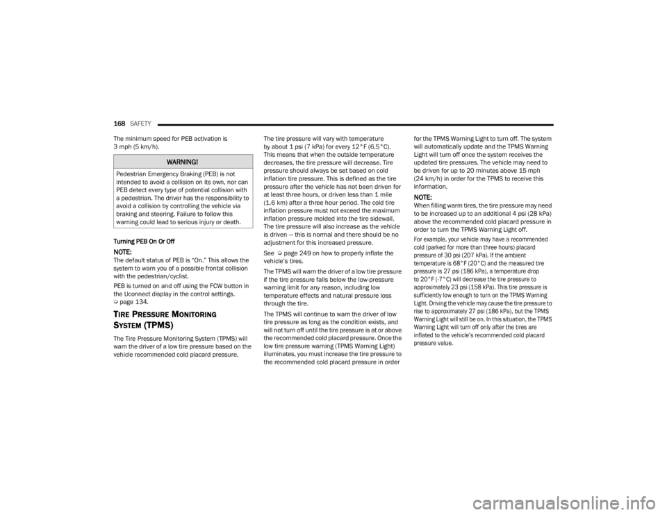
TIRE PRESSURE MONITORING
S
YSTEM (TPMS)
The Tire Pressure Monitoring System (TPMS) will
warn the driver of a low tire pressure based on the
vehicle recommended cold placard pressure. The tire pressure will vary with temperature
by about 1 psi (7 kPa) for every 12°F (6.5°C).
This means that when the outside temperature
decreases, the tire pressure will decrease. Tire
pressure should always be set based on cold
inflation tire pressure. This is defined as the tire
pressure after the vehicle has not been driven for
at least three hours, or driven less than 1 mile
(1.6 km) after a three hour period. The cold tire
inflation pressure must not exceed the maximum
inflation pressure molded into the tire sidewall.
The tire pressure will also increase as the vehicle
is driven — this is normal and there should be no
adjustment for this increased pressure.
See Ú
page 249 on how to properly inflate the
vehicle’s tires.
The TPMS will warn the driver of a low tire pressure
if the tire pressure falls below the low-pressure
warning limit for any reason, including low
temperature effects and natural pressure loss
through the tire.
The TPMS will continue to warn the driver of low
tire pressure as long as the condition exists, and
will not turn off until the tire pressure is at or above
the recommended cold placard pressure. Once the
low tire pressure warning (TPMS Warning Light)
illuminates, you must increase the tire pressure to
the recommended cold placard pressure in order for the TPMS Warning Light to turn off. The system
will automatically update and the TPMS Warning
Light will turn off once the system receives the
updated tire pressures. The vehicle may need to
be driven for up to 20 minutes above 15 mph
(24 km/h) in order for the TPMS to receive this
information.
NOTE:When filling warm tires, the tire pressure may need
to be increased up to an additional 4 psi (28 kPa)
above the recommended cold placard pressure in
order to turn the TPMS Warning Light off.
For example, your vehicle may have a recommended
cold (parked for more than three hours) placard
pressure of 30 psi (207 kPa). If the ambient
temperature is 68°F (20°C) and the measured tire
pressure is 27 psi (186 kPa), a temperature drop
to 20°F (-7°C) will decrease the tire pressure to
approximately 23 psi (158 kPa). This tire pressure is
sufficiently low enough to turn on the TPMS Warning
Light. Driving the vehicle may cause the tire pressure to
rise to approximately 27 psi (186 kPa), but the TPMS
Warning Light will still be on. In this situation, the TPMS
Warning Light will turn off only after the tires are
inflated to the vehicle’s recommended cold placard
pressure value.
WARNING!
Pedestrian Emergency Braking (PEB) is not
intended to avoid a collision on its own, nor can
PEB detect every type of potential collision with
a pedestrian. The driver has the responsibility to
avoid a collision by controlling the vehicle via
braking and steering. Failure to follow this
warning could lead to serious injury or death.
23_VF_OM_EN_USC_t.book Page 168
Page 171 of 296
SAFETY169
NOTE:
The TPMS is not intended to replace normal tire
care and maintenance or to provide warning of
a tire failure or condition.
The TPMS should not be used as a tire pressure
gauge while adjusting your tire pressure.
Driving on a significantly underinflated tire
causes the tire to overheat and can lead to tire
failure. Underinflation also reduces fuel effi -
ciency and tire tread life, and may affect the
vehicle’s handling and stopping ability.
The TPMS is not a substitute for proper tire
maintenance, and it is the driver’s responsibility
to maintain correct tire pressure using an accu -
rate tire pressure gauge, even if underinflation
has not reached the level to trigger illumination
of the TPMS Warning Light.
Seasonal temperature changes will affect tire
pressure, and the TPMS will monitor the actual
tire pressure in the tire Ú page 280.
Base System
This is the TPMS Warning Light located in
the instrument cluster.
The TPMS uses wireless technology with wheel
rim mounted electronic sensors to monitor tire
pressure levels. Sensors, mounted to each wheel as part of the valve stem, transmit tire pressure
readings to the receiver module.
NOTE:It is particularly important for you to check the tire
pressure in all of the tires on your vehicle regularly
and to maintain the proper pressure.
The TPMS consists of the following components:
Receiver module
Four Tire Pressure Monitoring System sensors
Tire Pressure Monitoring System Warning Light
Tire Pressure Monitoring System Low
Pressure Warnings
The Tire Pressure Monitoring System Warning Light
will illuminate in the instrument cluster, an audible
chime will be activated, and the “Check tire
pressure” message will display when one or more
of the four active road tire pressures are low.
Should this occur, you should stop as soon as
possible, check the inflation pressure of each
tire on your vehicle, and inflate each tire to the
vehicle’s recommended cold placard pressure
value. The system will automatically update and
the Tire Pressure Monitoring System Warning Light
will extinguish once the updated tire pressures
have been received. The vehicle may need to be
driven for up to 20 minutes above 15 mph
(24 km/h) to receive this information.
CAUTION!
The TPMS has been optimized for the original
equipment tires and wheels. TPMS pressures and
warning have been established for the tire size
equipped on your vehicle. Undesirable system
operation or sensor damage may result when
using replacement equipment that is not of the
same size, type, and/or style. Aftermarket wheels
can cause sensor damage.
Using aftermarket tire sealants may cause the Tire
Pressure Monitoring System (TPMS) sensor to
become inoperable. After using an aftermarket
tire sealant it is recommended that you take your
vehicle to an authorized dealership to have your
sensor function checked.
After inspecting or adjusting the tire pressure
always reinstall the valve stem cap. This will
prevent moisture and dirt from entering the
valve stem, which could damage the TPMS
sensor.
6
23_VF_OM_EN_USC_t.book Page 169