load RAM PROMASTER 2023 Owners Manual
[x] Cancel search | Manufacturer: RAM, Model Year: 2023, Model line: PROMASTER, Model: RAM PROMASTER 2023Pages: 296, PDF Size: 12.31 MB
Page 1 of 296

©2022 FCA US LLC. All Rights Reserved. Tous droits réservés. Ram is a registered trademark of FCA US LLC.
Ram est une marque déposée de FCA US LLC. App Store is a registered trademark of Apple Inc. Google Play Store is a registered trademark of Google.
2023 PROMASTER CITY
First Edition
23_VM_OM_EN_USC
Whether it is providing information about specific product features, taking a tour through your vehicle’s heritage, knowing what steps to take following an accident or scheduling your next appointment, we know you will find the app an important
extension of your Ram vehicle. Simply download the app, select your make and model and enjoy the ride. To get this app, go directly to the App Store
® or Google Play® Store and enter the search keyword “ram toolbox” (U.S. residents only).
DOWNLOAD THE MOST UP-TO-DATE OWNER’S MANUAL,
RADIO AND W
ARRANTY BOOKS
OWNERS.MOPAR.CA CANADA
MOPAR.COM/OM USA2023 PROMASTER CITY
OWNER’S MANUAL©2022 FCA US LLC. All Rights Reserved. Tous droits réservés. Ram is a registered trademark of FCA US LLC.
Ram est une marque déposée de FCA US LLC. App Store is a registered trademark of Apple Inc. Google Play Store is a registered trademark of Google.
2023 PROMASTER
Second Edition
23_VF_OM_EN_USC
Whether it is providing information about specific product features, taking a tour through your vehicle’s heritage, knowing what steps to take following an accident or scheduling your next appointment, we know you will find the app an important
extension of your Ram vehicle. Simply download the app, select your make and model and enjoy the ride. To get this app, go directly to the App Store
® or Google Play® Store and enter the search keyword “ram toolbox” (U.S. residents only).
DOWNLOAD THE MOST UP-TO-DATE OWNER’S MANUAL,
RADIO AND W
ARRANTY BOOKS
OWNERS.MOPAR.CA CANADAMOPAR.COM/OM
USA2023 PROMASTER
OWNER’S MANUAL
Page 6 of 296

4
Indications On The Display ........................... 102
Minimum Risk Maneuver.............................. 103 System Status................................................ 103
System Operation/Limitations ..................... 103
PARKSENSE FRONT/REAR PARK ASSIST —
IF EQUIPPED ........................................................ 104
ParkSense Sensors ....................................... 105
ParkSense Warning Display.......................... 105
ParkSense Display ........................................ 105
Enabling And Disabling ParkSense .............. 108
Service The ParkSense Park Assist
System ........................................................... 108ParkSense Park Assist Failure Indications .. 108
Cleaning The ParkSense System ................. 108ParkSense Park Assist System Usage
Precautions .................................................... 109
Side Distance Warning System ................... 110
PARKSENSE ACTIVE PARK ASSIST
SYSTEM — IF EQUIPPED ..................................... 112
Enabling And Disabling The ParkSense
Active Park Assist System ............................. 112
Parallel/Perpendicular Parking Space
Assistance Operation .................................... 113
Exiting The Parking Space ............................ 116
LANESENSE — IF EQUIPPED ............................. 116
LaneSense Operation ................................... 116Turning LaneSense On Or Off ....................... 117
LaneSense Warning Message ...................... 117Changing LaneSense Status ........................ 119
PARKVIEW REAR BACK UP CAMERA .............. 119 SURROUND VIEW CAMERA SYSTEM —
IF EQUIPPED ........................................................ 120
REFUELING THE VEHICLE ................................... 122
Loose Fuel Filler Cap Message .................... 123
VEHICLE LOADING .............................................. 123
Vehicle Certification Label ............................ 123
Gross Vehicle Weight Rating (GVWR) .......... 123
Gross Axle Weight Rating (GAWR) ............... 123
Tire Size ......................................................... 123
Rim Size ......................................................... 124
Inflation Pressure .......................................... 124
Curb Weight ................................................... 124
Overloading.................................................... 124
Loading ......................................................... 124
TRAILER TOWING ................................................ 124
Common Towing Definitions......................... 124
Trailer Hitch Classification ............................ 126
Trailer Towing Weights (Maximum Trailer
Weight Ratings) ............................................ 126
Trailer And Tongue Weight ........................... 127Towing Requirements .................................. 127
Towing Tips ................................................... 130
RECREATIONAL TOWING (BEHIND
MOTORHOME) .................................................... 130
Towing This Vehicle Behind Another
Vehicle ........................................................... 130
Recreational Towing...................................... 131
DRIVING TIPS ....................................................... 131
Driving On Slippery Surfaces ....................... 131
Driving Through Water ................................. 131
MULTIMEDIA
UCONNECT SYSTEMS ......................................... 133
CYBERSECURITY ................................................. 133
UCONNECT SETTINGS ........................................ 134 Customer Programmable Features ............. 134
RADIO OPERATION AND MOBILE PHONES...... 151
Regulatory And Safety Information .............. 151
SAFETY
SAFETY FEATURES .............................................. 152Anti-Lock Brake System (ABS)...................... 152
Electronic Brake Control (EBC) System ...... 153
DROWSY DRIVER DETECTION (DDD) —
IF EQUIPPED ......................................................... 157
To Activate/Deactivate ................................. 157
System Operation.......................................... 157
AUXILIARY DRIVING SYSTEMS .......................... 158
Blind Spot Monitoring (BSM) —
If Equipped ................................................... 158
Forward Collision Warning (FCW) With
Mitigation — If Equipped ............................... 164
Tire Pressure Monitoring
System (TPMS) .............................................. 168
OCCUPANT RESTRAINT SYSTEMS ................... 170
Occupant Restraint Systems Features ....... 170
Important Safety Precautions ...................... 170
Seat Belt Systems ........................................ 171
Supplemental Restraint Systems (SRS) ...... 178Child Restraints ............................................. 185
23_VF_OM_EN_USC_t.book Page 4
Page 23 of 296
GETTING TO KNOW YOUR VEHICLE21
(Continued)
SECURITY SYSTEM MANUAL OVERRIDE
The Vehicle Security system will not arm if you lock
the doors using the manual door lock.
DOORS
POWER DOOR LOCKS
The power lock/unlock button has an LED that
indicates whether the doors are locked or
unlocked.
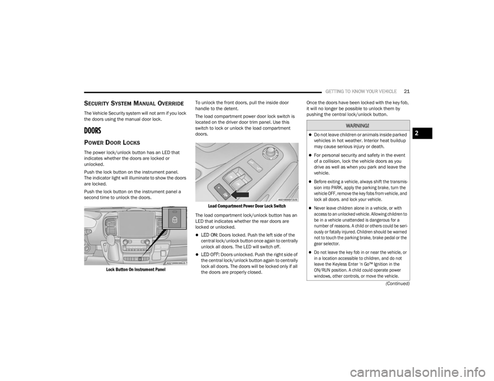
Push the lock button on the instrument panel.
The indicator light will illuminate to show the doors
are locked.
Push the lock button on the instrument panel a
second time to unlock the doors.
Lock Button On Instrument Panel
To unlock the front doors, pull the inside door
handle to the detent.
The load compartment power door lock switch is
located on the driver door trim panel. Use this
switch to lock or unlock the load compartment
doors.
Load Compartment Power Door Lock Switch
The load compartment lock/unlock button has an
LED that indicates whether the rear doors are
locked or unlocked.
LED ON:
Doors locked. Push the left side of the
central lock/unlock button once again to centrally
unlock all doors. The LED will switch off.
LED OFF: Doors unlocked. Push the right side of
the central lock/unlock button again to centrally
lock all doors. The doors will be locked only if all
the doors are properly closed. Once the doors have been locked with the key fob,
it will no longer be possible to unlock them by
pushing the central lock/unlock button.
WARNING!
Do not leave children or animals inside parked
vehicles in hot weather. Interior heat buildup
may cause serious injury or death.
For personal security and safety in the event
of a collision, lock the vehicle doors as you
drive as well as when you park and leave the
vehicle.
Before exiting a vehicle, always shift the transmis
-
sion into PARK, apply the parking brake, turn the
vehicle OFF, remove the key fobs from vehicle, and
lock all doors. and lock your vehicle.
Never leave children alone in a vehicle, or with
access to an unlocked vehicle. Allowing children to
be in a vehicle unattended is dangerous for a
number of reasons. A child or others could be seri -
ously or fatally injured. Children should be warned
not to touch the parking brake, brake pedal or the
gear selector.
Do not leave the key fob in or near the vehicle, or
in a location accessible to children, and do not
leave the Keyless Enter ‘n Go™ Ignition in the
ON/RUN position. A child could operate power
windows, other controls, or move the vehicle.
2
23_VF_OM_EN_USC_t.book Page 21
Page 24 of 296

22GETTING TO KNOW YOUR VEHICLE
AUTO UNLOCK DOORS
This feature unlocks all front doors when one front
door is opened.
NOTE:If the rear or side door is open, only the rear or side
door is unlocked. Automatic Unlock On Exit Feature
If Auto Unlock is enabled within Uconnect Settings
Ú
page 134, this feature will unlock all the doors
when any door is opened if the vehicle is stopped
and in PARK.
KEYLESS ENTER ‘N GO™ — PASSIVE
E
NTRY
The Passive Entry system is an enhancement
to the vehicle’s key fob and a feature of Keyless
Enter ‘n Go™ — Passive Entry. This feature allows
you to lock and unlock the vehicle’s door(s) without
having to push the key fob lock or unlock buttons.
NOTE:
Passive Entry may be programmed on or off
within Uconnect Settings Ú page 134.
The key fob may not be detected by the vehicle
Passive Entry system if it is located next to a
mobile phone, laptop, or other electronic device;
these devices may block the key fob’s wireless
signal and prevent the Passive Entry system
from locking/unlocking the vehicle.
Passive Entry Unlock initiates illuminated
approach (low beams, license plate lamp,
position lamps) for whichever duration is set
between 0, 30, 60 or 90 seconds. Passive Entry
Unlock also initiates two flashes of the turn
signals.
If the vehicle is unlocked by Passive Entry and
no door is opened within 60 seconds, the
vehicle will relock and (if equipped) will arm
the Vehicle Security system.
To Unlock From The Driver, Passenger or Rear
Door
With a valid Passive Entry key fob within 5 ft
(1.5 m) of the door handle, push the Passive Entry
button next to the handle to unlock the vehicle.
Unlock the front doors only if the Uconnect
setting is set to "Approach" and you press the
button located next to the front handle.
Unlock the load compartment doors only if the
Uconnect setting is set to "Approach" and you
press the button located next to the rear handle.
The Passive Entry feature will be disabled if the
Uconnect setting is set to "Off".
NOTE:
Either the load compartment and cabin
compartment or all doors will unlock when
you press Passive Entry button, depending on
the selected setting in the Uconnect system
Ú page 134.
Driving with the rear doors open can allow
poisonous exhaust gases into your vehicle.
You and your passengers could be injured by
these fumes. Keep the rear doors closed
when you are operating the vehicle.
If you are required to drive with the rear doors
open, make sure that all windows are closed and
the climate control blower control is set to a high
speed. DO NOT use the recirculation mode.
CAUTION!
An unlocked vehicle is an invitation. Always remove
the key fob from the vehicle and lock all of the doors
when leaving the vehicle unattended.
WARNING!
23_VF_OM_EN_USC_t.book Page 22
Page 48 of 296

46GETTING TO KNOW YOUR VEHICLE
(Continued)
POWER OUTLETS
Passenger Compartment Power Outlet
The power outlet is located on the instrument
panel to the right of the radio. It only operates with
the ignition in the ON/RUN position.
Passenger Compartment Power Outlet
Load Compartment Power Outlet — If Equipped
The load compartment power outlet is located in
the rear cargo compartment. The outlet can be is
used for powering 12 Volt adapter accessories and
recharging communications devices.
Load Compartment Power Outlet
NOTE:Do not connect devices with power higher than
180 W to the socket. Do not damage the socket by
using unsuitable adapters.
Power Outlet Fuses — Under Hood
1 — F14 Fuse 20 Amp Yellow Front Power Outlet
2 — F09 Fuse 15 Amp Blue Rear Power Outlet
WARNING!
To avoid serious injury or death:
Only devices designed for use in this type of outlet
should be inserted into any 12 Volt outlet.
Do not touch with wet hands.
Close the lid when not in use and while driving
the vehicle.
If this outlet is mishandled, it may cause an
electric shock and failure.
CAUTION!
Many accessories that can be plugged in draw
power from the vehicle's battery, even when not in
use (i.e., cellular phones, etc.). Eventually, if
plugged in long enough, the vehicle's battery
will discharge sufficiently to degrade battery life
and/or prevent the engine from starting.
Accessories that draw higher power (i.e., coolers,
vacuum cleaners, lights, etc.) will degrade the
battery even more quickly. Only use these intermit -
tently and with greater caution.
23_VF_OM_EN_USC_t.book Page 46
Page 49 of 296

GETTING TO KNOW YOUR VEHICLE47
POWER INVERTER — IF EQUIPPED
There is a 115 Volt, 150 Watt inverter outlet
located on the instrument panel, to the right of
the radio, to convert DC current to AC current.
This outlet can power cellular phones, electronics
and other low power devices requiring power up to
150 Watts. Certain game consoles will exceed this
power limit, as will most power tools.
Power Inverter Location
To turn on the power inverter outlet, simply plug in
the device. The outlet automatically turns off when
the device is unplugged.
The power inverter is designed with built-in overload
protection. If the power rating of 150 Watts is
exceeded, the power inverter will automatically shut
down. Once the electrical device has been removed
from the outlet the inverter should automatically reset.
To avoid overloading the circuit, check the power
ratings on electrical devices prior to using the inverter.
AUXILIARY SWITCHES — IF EQUIPPED
Your vehicle may be equipped with two auxiliary
switches located on the instrument panel to the
left of the steering column which can be used to
power various electronic devices. Connections to
the switches are found in the right central pillar
fuse panel at the base of the passenger side
B-pillar.
Auxiliary Switches
Auxiliary Switch 1 is configured to constant battery
feed, while Auxiliary Switch 2 is configured to
ignition feed.
For further information on using the auxiliary
switches, please refer to the Ram Body Builder’s
Guide by accessing
www.rambodybuilder.com
and choosing the appropriate links.
After the use of high power draw accessories, or
long periods of the vehicle not being started (with
accessories still plugged in), the vehicle must be
driven a sufficient length of time to allow the
generator to recharge the vehicle's battery.
CAUTION!
WARNING!
To avoid serious injury or death:
Do not insert any objects into the receptacles.
Do not touch with wet hands.
Close the lid when not in use.
If this outlet is mishandled, it may cause an
electric shock and failure.
2
23_VF_OM_EN_USC_t.book Page 47
Page 81 of 296

STARTING AND OPERATING79
(Continued)
If the Auto Park Brake feature is enabled, the
parking brake will automatically engage whenever
the transmission is placed into PARK. If your foot is
on the brake pedal, you may notice a small amount
of brake pedal movement while the parking brake
is engaging.
The parking brake will release automatically when
the ignition is ON, the transmission is in DRIVE or
REVERSE, the driver seat belt is buckled, and an
attempt is made to drive away.
To release the parking brake manually, the ignition
switch must be in the ON/RUN position. Put your
foot on the brake pedal, then push the parking
brake switch down momentarily. You may hear a
slight whirring sound from the back of the vehicle
while the parking brake disengages. You may also
notice a small amount of movement in the brake
pedal. Once the parking brake is fully disengaged,
the Brake Warning Light in the instrument cluster
and the LED indicator on the switch will extinguish.
NOTE:When parking on a hill, it is important to turn the
front wheels toward the curb on a downhill grade
and away from the curb on an uphill grade. Apply
the parking brake before placing the gear selector
in PARK, otherwise the load on the transmission
locking mechanism may make it difficult to move
the gear selector out of PARK.
If exceptional circumstances should make it
necessary to engage the parking brake while the
vehicle is in motion, maintain upward pressure
on the EPB switch for as long as engagement is
desired. The Brake Warning Light will illuminate,
and a continuous chime will sound. The rear stop
lamps will also be illuminated automatically while
the vehicle remains in motion.
To disengage the parking brake while the vehicle
is in motion, release the switch. If the vehicle is
brought to a complete stop using the parking
brake, when the vehicle reaches approximately
3 mph, (5 km/h) the parking brake will remain
engaged.
WARNING!
Never use the PARK position as a substitute
for the parking brake. Always apply the
parking brake fully when parked to guard
against vehicle movement and possible injury
or damage.
When exiting the vehicle, always take the key
fob with you and lock your vehicle.
Never leave children alone in a vehicle, or with
access to an unlocked vehicle. Allowing children to
be in a vehicle unattended is dangerous for a
number of reasons. A child or others could be seri
-
ously or fatally injured. Children should be warned
not to touch the parking brake, brake pedal or the
gear selector.
Do not leave the key fob in or near the vehicle,
or in a location accessible to children, and do
not leave a vehicle equipped with Keyless
Enter ‘n Go™ in the ACC or ON/RUN position.
A child could operate power windows, other
controls, or move the vehicle.
Be sure the parking brake is fully disengaged
before driving; failure to do so can lead to
brake failure and a collision.
Always fully apply the parking brake when leaving
your vehicle, or it may roll and cause damage or
injury. Also be certain to leave the transmission in
PARK. Failure to do so may allow the vehicle to roll
and cause damage or injury.
CAUTION!
If the Brake System Warning Light remains on
with the parking brake released, a brake system
malfunction is indicated. Have the brake system
serviced by an authorized dealer immediately.
WARNING!
4
23_VF_OM_EN_USC_t.book Page 79
Page 84 of 296

82STARTING AND OPERATING
NOTE:Swivel seats that are unlocked can also prevent
the transmission gear selector from being moved
out of the PARK position. To shift the transmission
out of the PARK position the first time after
cranking is allowed, ensure swivel seats are locked
in the forward facing position.
9-SPEED AUTOMATIC TRANSMISSION
The transmission gear position display (located in
the instrument cluster) indicates the transmission
gear range. You must press the brake pedal to
move the gear selector out of PARK. To drive, move
the gear selector from PARK or NEUTRAL to the
DRIVE position.
The electronically controlled transmission provides
a precise shift schedule. The transmission
electronics are self-calibrating; therefore, the first
few shifts on a new vehicle may be somewhat
abrupt. This is a normal condition, and precision
shifts will develop within a few hundred miles
(kilometers).
Gear Selector
Only shift from DRIVE to PARK or REVERSE when
the accelerator pedal is released and the vehicle is
stopped. Be sure to keep your foot on the brake
pedal when shifting between these gears.
The transmission gear selector provides PARK,
REVERSE, NEUTRAL, DRIVE, and Electronic Range
Select (ERS) shift positions. Manual downshifts
can be made using the ERS shift control. Moving
the gear selector into the ERS “-”/”+” position
(beside the DRIVE position) activates ERS mode,
displays the current gear in the instrument cluster,
and prevents automatic upshifts beyond this gear.
In ERS mode, toggling the gear selector forward “-”
or rearward “+” will change the highest available
gear Ú page 85.
NOTE:If the gear selector cannot be moved to the PARK,
REVERSE, or NEUTRAL position (when pushed forward) it is probably in the ERS “+”/”-” position
(beside the DRIVE position). In ERS mode, the
transmission gear limit (1, 2, 3, etc.) is displayed in
the instrument cluster. Move the gear selector to
the right (into the DRIVE [D] position) for access to
PARK, REVERSE, and NEUTRAL.
Gear Ranges
Do not press the accelerator pedal when shifting
out of PARK or NEUTRAL.
NOTE:After selecting any gear range, wait a moment to
allow the selected gear to engage before acceler
-
ating. This is especially important when the engine
is cold.
PARK (P)
This range supplements the parking brake by
locking the transmission. The engine can be
started in this range. Never attempt to use PARK
while the vehicle is in motion. Apply the parking
brake when exiting the vehicle in this range.
When parking on a hill, apply the parking brake
before shifting the transmission to PARK,
otherwise the load on the transmission locking
mechanism may make it difficult to move the gear
selector out of PARK. As an added precaution, turn
the front wheels toward the curb on a downhill
grade, and away from the curb on an uphill grade.
23_VF_OM_EN_USC_t.book Page 82
Page 86 of 296

84STARTING AND OPERATING
REVERSE (R)
This range is for moving the vehicle backward.
Shift into REVERSE only after the vehicle has come
to a complete stop.
NEUTRAL (N)
Use this range when the vehicle is standing
for prolonged periods with the engine running.
The engine may be started in this range. Apply the
parking brake and shift the transmission into PARK
if you must exit the vehicle.
DRIVE (D)
This range should be used for most city and
highway driving. It provides the smoothest upshifts
and downshifts, and the best fuel economy.
The transmission automatically upshifts through
all forward gears.
When frequent transmission shifting occurs (such
as when operating the vehicle under heavy loading
conditions, in hilly terrain, traveling into strong
head winds, or while towing a heavy trailer), select
TOW/HAUL mode or use the Electronic Range
Select (ERS) shift control to select a lower gear
range Úpage 85. Under these conditions, using a
lower gear range will improve performance and
extend transmission life by reducing excessive
shifting and heat buildup.
During cold temperatures, transmission operation may
be modified depending on engine and transmission
temperature as well as vehicle speed. This feature
improves warm-up time of the engine and transmission
to achieve maximum efficiency. During extremely cold temperatures (-16°F [-27°C] or below), operation may
briefly be limited to THIRD gear only. Normal operation
will resume once the transmission temperature has
risen to a suitable level.
Transmission Limp Home Mode
Transmission function is monitored electronically for
abnormal conditions. If a condition is detected that
could result in transmission damage, Transmission
Limp Home Mode is activated. In this mode, the
transmission remains in THIRD gear regardless of
which forward gear is selected. PARK, REVERSE, and
NEUTRAL will continue to operate. The Malfunction
Indicator Light (MIL) may be illuminated. Transmission
Limp Home Mode allows the vehicle to be driven to an
authorized dealer for service without damaging the
transmission.
In the event of a momentary problem, the
transmission can be reset to regain all forward
gears by performing the following steps:
1. Stop the vehicle.
2. Shift the transmission into PARK.
3. Turn the ignition OFF.
4. Wait approximately 10 seconds.
5. Restart the engine.
6. Shift into the desired gear range. If the
problem is no longer detected, the
transmission will return to normal operation.
CAUTION!
Before moving the transmission gear selector
out of PARK, you must turn the ignition to the
ON/RUN position, and also press the brake
pedal. Otherwise, damage to the gear selector
could result.
DO NOT race the engine when shifting from
PARK or NEUTRAL into another gear range, as
this can damage the drivetrain.
WARNING!
Do not coast in NEUTRAL and never turn off the
ignition to coast down a hill. These are unsafe
practices that limit your response to changing
traffic or road conditions. You might lose control
of the vehicle and have a collision.
CAUTION!
Towing the vehicle, coasting, or driving for any
other reason with the transmission in NEUTRAL
can cause severe transmission damage.
For Recreational Towing Ú page 130.
For Towing A Disabled Vehicle Ú page 219.
23_VF_OM_EN_USC_t.book Page 84
Page 87 of 296

STARTING AND OPERATING85
NOTE:Even if the transmission can be reset, we
recommend that you visit an authorized dealer at
your earliest possible convenience. An authorized
dealer has diagnostic equipment to assess the
condition of your transmission. If the transmission
cannot be reset, authorized dealer service is
required.
Electronic Range Select (ERS) Operation
The ERS shift control allows the driver to select the max
gear limit. For example, if you set the transmission gear
limit to FOURTH gear, the transmission will not shift
above FOURTH gear, but will shift through the lower
gears normally.
You can switch between DRIVE and ERS mode at any
vehicle speed. When the gear selector is in the DRIVE
position, the transmission will operate automatically,
shifting between all available gears. Moving the gear
selector to the ERS position (beside DRIVE) will activate
ERS mode, display the current gear in the instrument
cluster, and set that gear as the max gear limit. Once in
ERS mode, moving the gear selector forward “-” or
rearward “+” will change the max gear limit.
NOTE:The transmission will still continue to use the
optimal highest gear, for the current driving condi -
tions, within the selected gear range limit.
To exit ERS mode, simply return the gear selector
to the DRIVE position.
NOTE:To select the proper gear position for maximum
deceleration (engine braking), move the gear
selector into the ERS position, then tap it forward
“-” repeatedly as the vehicle slows. The trans -
mission will shift to the range from which the
vehicle can best be slowed down.
When To Use TOW/HAUL Mode
When driving in hilly areas, towing a trailer, carrying a
heavy load, etc., and frequent transmission shifting
occurs, push the TOW/HAUL switch to activate
TOW/HAUL mode. This will improve performance and
reduce the potential for transmission overheating or
failure due to excessive shifting. When operating in
TOW/HAUL mode, transmission upshifts are delayed,
and the transmission will automatically downshift
(for engine braking) during steady braking maneuvers.
The TOW/HAUL Indicator Light will illuminate in the
instrument cluster to indicate that TOW/HAUL
mode has been activated. Pushing the switch a
second time restores normal operation. Normal operation is always the default at engine start-up.
If TOW/HAUL mode is desired, the switch must be
pushed each time the engine is started.
POWER STEERING
The electric power steering system will provide
increased vehicle response and ease of
maneuverability. The power steering system
adapts to different driving conditions.
If the steering icon is flashing, it indicates that the
vehicle needs to be taken to the dealer for service.
It is likely the vehicle has lost power steering
assistance.
If the steering icon is displayed and the
“POWER STEERING SYSTEM OVER TEMP”
message is displayed on the instrument cluster
screen, this indicates an over temperature
condition in the power steering system. Once
driving conditions are safe, pull over and let the
vehicle idle for a few moments until the icon and
message turn off Ú
page 56.
If the steering icon is displayed and the
“SERVICE POWER STEERING – ASSIST OFF”
message is displayed on the instrument cluster
screen, this indicates the vehicle needs to be
taken to the dealer for service Ú page 56.
WARNING!
Do not downshift for additional engine braking
on a slippery surface. The drive wheels could
lose their grip and the vehicle could skid,
causing a collision or personal injury.
4
23_VF_OM_EN_USC_t.book Page 85