start stop button RAM PROMASTER 2023 Owners Manual
[x] Cancel search | Manufacturer: RAM, Model Year: 2023, Model line: PROMASTER, Model: RAM PROMASTER 2023Pages: 296, PDF Size: 12.31 MB
Page 18 of 296
16GETTING TO KNOW YOUR VEHICLE
NOTE:
’ü¼When having the Sentry Key Immobilizer system
serviced, bring all vehicle keys with you to an
authorized dealer.
’ü¼Keys must be ordered to the correct key cut to
match the vehicle locks.
’ü¼It is not mandatory to replace the key fob if a
new emergency key is needed, and vice versa.
SENTRY KEY
The Sentry Key Immobilizer system prevents
unauthorized vehicle operation by disabling the
engine. The system does not need to be armed or
activated. Operation is automatic, regardless of
whether the vehicle is locked or unlocked.
The system uses a key fob, keyless push button
ignition and a Radio Frequency (RF) receiver to
prevent unauthorized vehicle operation. Therefore,
only key fobs that are programmed to the vehicle
can be used to start and operate the vehicle.
The system will shut the engine off in two seconds
if an invalid key fob is used to start the engine.
After placing the ignition switch in the ON/RUN
position, the Vehicle Security Light will turn on for
three seconds for a bulb check. If the light remains on after the bulb check, it indicates that there is a
problem with the electronics. In addition, if the light
begins to flash after the bulb check, it indicates
that someone used an invalid key fob to start the
engine. Either of these conditions will result in the
engine being shut off after two seconds.
If the Vehicle Security Light turns on during normal
vehicle operation (vehicle running for longer than
10 seconds), it indicates that there is a fault in the
electronics. Should this occur, have the vehicle
serviced as soon as possible by an authorized dealer.
All of the key fobs provided with your new vehicle
have been programmed to the vehicle electronics
Ú
page 280.
NOTE:A key fob that has not been programmed is also
considered an invalid key.
IGNITION SWITCH
KEYLESS ENTER ŌĆśN GOŌäó IGNITION
This feature allows the driver to operate the
ignition switch with the push of a button as long as
the key fob is in the passenger compartment within
the area of the front driver and passenger seats.
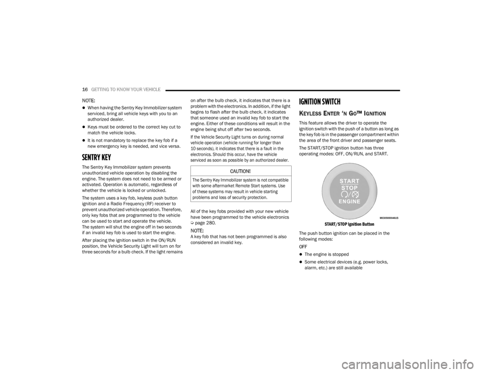
The START/STOP ignition button has three
operating modes: OFF, ON/RUN, and START.
START/STOP Ignition Button
The push button ignition can be placed in the
following modes:
OFF
’ü¼The engine is stopped
’ü¼Some electrical devices (e.g. power locks,
alarm, etc.) are still available
CAUTION!
The Sentry Key Immobilizer system is not compatible
with some aftermarket Remote Start systems. Use
of these systems may result in vehicle starting
problems and loss of security protection.
23_VF_OM_EN_USC_t.book Page 16
Page 19 of 296
GETTING TO KNOW YOUR VEHICLE17
ON/RUN
’ü¼Driving position
’ü¼All electrical devices are available (e.g. climate
controls, heated seats, etc.)
START
’ü¼The engine will start (when foot is on the brake)
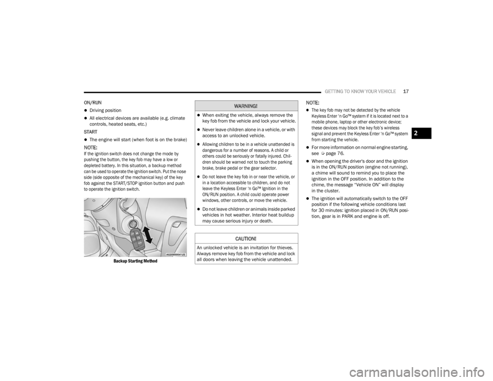
NOTE:
If the ignition switch does not change the mode by
pushing the button, the key fob may have a low or
depleted battery. In this situation, a backup method
can be used to operate the ignition switch. Put the nose
side (side opposite of the mechanical key) of the key
fob against the START/STOP ignition button and push
to operate the ignition switch.
Backup Starting Method
NOTE:
’ü¼The key fob may not be detected by the vehicle
Keyless Enter ŌĆśn GoŌäó system if it is located next to a
mobile phone, laptop or other electronic device;
these devices may block the key fobŌĆÖs wireless
signal and prevent the Keyless Enter ŌĆśn GoŌäó system
from starting the vehicle.
’ü¼For more information on normal engine starting,
see Úpage 76.
’ü¼When opening the driver's door and the ignition
is in the ON/RUN position (engine not running),
a chime will sound to remind you to place the
ignition in the OFF position. In addition to the
chime, the message ŌĆ£Vehicle ONŌĆØ will display
in the cluster.
’ü¼The ignition will automatically switch to the OFF
position if the following vehicle conditions last
for 30 minutes: ignition placed in ON/RUN posi -
tion, gear is in PARK and engine is off.
WARNING!
’ü¼When exiting the vehicle, always remove the
key fob from the vehicle and lock your vehicle.
’ü¼Never leave children alone in a vehicle, or with
access to an unlocked vehicle.
’ü¼Allowing children to be in a vehicle unattended is
dangerous for a number of reasons. A child or
others could be seriously or fatally injured. Chil -
dren should be warned not to touch the parking
brake, brake pedal or the gear selector.
’ü¼Do not leave the key fob in or near the vehicle, or
in a location accessible to children, and do not
leave the Keyless Enter ŌĆśn GoŌäó Ignition in the
ON/RUN position. A child could operate power
windows, other controls, or move the vehicle.
’ü¼Do not leave children or animals inside parked
vehicles in hot weather. Interior heat buildup
may cause serious injury or death.
CAUTION!
An unlocked vehicle is an invitation for thieves.
Always remove key fob from the vehicle and lock
all doors when leaving the vehicle unattended.
2
23_VF_OM_EN_USC_t.book Page 17
Page 21 of 296

GETTING TO KNOW YOUR VEHICLE19
TO EXIT REMOTE START MODE
To drive the vehicle after starting the Remote Start
system, push and release the START/STOP ignition
button while pressing the brake pedal prior to the
end of the 15 minute cycle.
The Remote Start system will turn the engine off if
the Remote Start button on the key fob is pushed
again, or if the engine is allowed to run for the
entire 15 minute cycle. Once the ignition is placed
in the ON/RUN position, the climate controls
will resume the previously set operations
(temperature, blower control, etc.).
NOTE:To avoid unintentional shutdowns, the system will
disable for two seconds after receiving a valid
Remote Start request.
For vehicles equipped with the Keyless Enter ŌĆśn GoŌäó ŌĆö
Passive Entry feature, the message ŌĆ£Remote Start
Active ŌĆö Push Start ButtonŌĆØ will display in the
instrument cluster display until you push the
START/STOP ignition button.
REMOTE START DEFROST MODE
A
CTIVATION ŌĆö IF EQUIPPED
When Remote Start is active, and the outside
ambient temperature is 40┬░F (4.5┬░C) or below, the
system will automatically activate rear defrost for
15 minutes or less. The timing is dependent on
the ambient temperature. Once the timer expires,
the system will automatically adjust the settings
depending on ambient conditions. See ŌĆ£Remote
Start Comfort Systems ŌĆö If EquippedŌĆØ in the next
section for detailed operation.
REMOTE START COMFORT SYSTEMS ŌĆö
I
F EQUIPPED
When Remote Start is activated, the rear defrost
will automatically turn on in cold weather.
The vehicle will adjust the climate control settings
depending on the outside ambient temperature.
Manual Temperature Control (MTC) ŌĆö If Equipped
’ü¼In ambient temperatures of 40┬░F (4.5┬░C) or
below, the climate settings will default to
maximum heat, with fresh air entering the
cabin. If the front defrost timer expires, the
vehicle will enter Mix Mode.
’ü¼In ambient temperatures from 40┬░F (4.5┬░C) to
78┬░F (26┬░C), the climate settings will be based
on the last settings selected by the driver.
’ü¼In ambient temperatures of 78┬░F (26┬░C)
or above, the climate settings will default to
MAX A/C, Bi-Level mode, with Recirculation on.
For more information on ATC, MTC, and climate
control settings, see Ú page 40.
NOTE:These features will stay on through the duration of
Remote Start, or until the ignition is placed in the
ON/RUN position. The climate control settings
will change, and exit the automatic defaults, if
manually adjusted by the driver while the vehicle is
in Remote Start mode. This includes turning the
climate controls off using the OFF button.
REMOTE START WINDSHIELD WIPER
D
E-ICER ACTIVATION ŌĆö IF EQUIPPED
When Remote Start is active and the outside
ambient temperature is less than 33┬░F (0.6┬░C),
the Windshield Wiper De-Icer will activate. Exiting
Remote Start will resume its previous operation.
If the Windshield Wiper De-Icer was active, the
timer and operation will continue.
2
23_VF_OM_EN_USC_t.book Page 19
Page 31 of 296
GETTING TO KNOW YOUR VEHICLE29
UCONNECT VOICE RECOGNITION ŌĆö
IF EQUIPPED
INTRODUCING VOICE RECOGNITION
Start using Uconnect Voice Recognition with
these helpful quick tips. It provides the key Voice
Commands and tips you need to know to control
your vehicleŌĆÖs Voice Recognition (VR) system.
NOTE:Voice Recognition is only available on the
Uconnect 5 NAV With 10.1-inch Display.
BASIC VOICE COMMANDS
The following can be given at any point while using
your Uconnect system.
Push the VR button and after the beep, say a
command. You can also say the system ŌĆ£Wake UpŌĆØ
word, ŌĆ£Hey UconnectŌĆØ or ŌĆ£Hey RamŌĆØ, and then say
a command. The factory default Wake Up word is
set to ŌĆ£Hey UconnectŌĆØ and can be reprogrammed
through the Uconnect Settings. After the beep, say:
’ü¼ŌĆ£Cancel ŌĆØ to stop a current voice session.
’ü¼ŌĆ£Help ŌĆØ to hear a list of suggested Voice
Commands.
’ü¼ŌĆ£ Repeat ŌĆØ to listen to the system prompts again.
Notice the visual cues that inform you of your Voice
Recognition systemŌĆÖs status.
GET STARTED
The VR button is used to activate/deactivate
your Voice Recognition system. You can also use
the systemŌĆÖs ŌĆ£Wake UpŌĆØ word to activate voice
recognition. The ŌĆ£Wake UpŌĆØ word can be set
through the Uconnect Settings Ú page 134.
Helpful hints for using Voice Recognition:
’ü¼Reduce background noise. Wind noise and
passenger conversations are examples of noise
that may impact recognition.
’ü¼Speak clearly at a normal pace and volume
while facing straight ahead.
’ü¼Each time you give a Voice Command, first push the
VR button, wait until after the beep, then say your
Voice Command. Also, you can say the vehicle
ŌĆ£Wake UpŌĆØ word to issue a Voice Command.
The available ŌĆ£Wake UpŌĆØ words are ŌĆ£Hey UconnectŌĆØ
and ŌĆ£Hey RamŌĆØ.
’ü¼You can interrupt the help message or system
prompts by pushing the VR button and saying a
Voice Command from the current category.
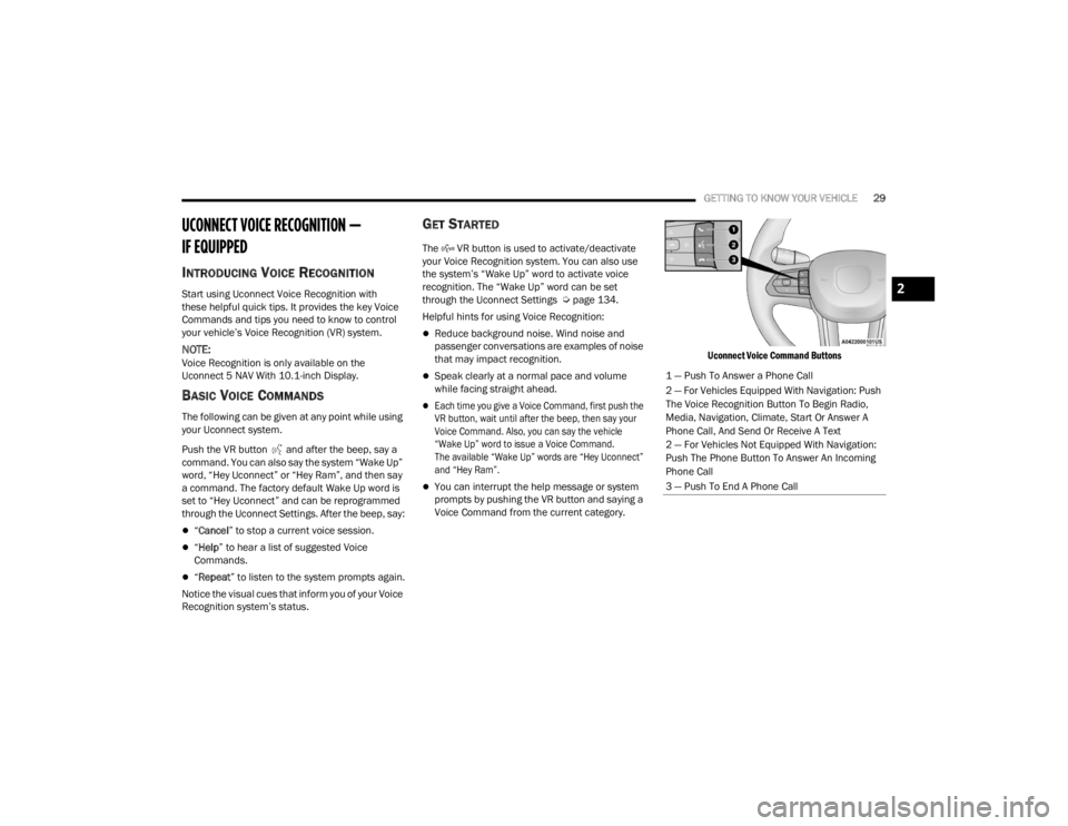
Uconnect Voice Command Buttons
1 ŌĆö Push To Answer a Phone Call
2 ŌĆö For Vehicles Equipped With Navigation: Push
The Voice Recognition Button To Begin Radio,
Media, Navigation, Climate, Start Or Answer A
Phone Call, And Send Or Receive A Text
2 ŌĆö For Vehicles Not Equipped With Navigation:
Push The Phone Button To Answer An Incoming
Phone Call
3 ŌĆö Push To End A Phone Call
2
23_VF_OM_EN_USC_t.book Page 29
Page 69 of 296

GETTING TO KNOW YOUR INSTRUMENT PANEL67
Drowsy Driver Detected Warning Light ŌĆö
If Equipped
Drowsy driver detection helps to avoid
crashes caused by fatigue by advising
drivers to take a break in time. Once a
Drowsy Driver is detected, A pop-up will
display continuously until the driver presses the
OK button to clear.
Once the pop-up message is cleared, it is stored
until the condition is no longer true.
Electric Power Steering (EPS) Fault
Warning Light
This warning light will turn on when
there's a fault with the EPS system
Ú page 85.
Electronic Throttle Control (ETC) Warning
Light
This warning light will illuminate to inform of
a problem with the ETC system. If a problem
is detected while the vehicle is running, the
light will either stay on or flash depending on
the nature of the problem. Cycle the ignition when
the vehicle is safely and completely stopped and the
transmission is placed in the PARK (P) position.
The light should turn off. If the light remains on with the
vehicle running, your vehicle will usually be drivable;
however, see an authorized dealer for service as soon
as possible.
If the light continues to flash when the vehicle is
running, immediate service is required and you may
experience reduced performance, an elevated/
rough idle, or engine stall and your vehicle may
require towing. The light will come on when the
ignition is placed in the ON/RUN or MAR/ON/RUN
position and remain on briefly as a bulb check. If the
light does not come on during starting, have the
system checked by an authorized dealer.
Engine Temperature Warning Light
This light warns of an overheated
engine condition. If the engine coolant
temperature is too high, this indicator will
illuminate and a single chime will sound.
If the light turns on while driving, safely pull over and
stop the vehicle. If the Air Conditioning (A/C) system is
on, turn it off. Also, shift the transmission into NEUTRAL
and idle the vehicle. If the temperature reading does
not return to normal, turn the engine off immediately
and call for service
Ú
page 216.
Generic Warning Light
The Generic Warning Light will illuminate
to signal the failure of one or more safety
warning lights with a corresponding
message. The safety systems that may
cause the Generic Warning Light to illuminate
include but are not limited too: Seat belt Reminder,
Electric Park Brake, Brakes, Air Bag, and Swivel
Seat failure.
The telltale will remain on in case of swivel seat
failure and will blink in case of Air Bag Warning
Light Failure. Contact an authorized dealer
immediately for service.
WARNING!
Continued operation with reduced assist could
pose a safety risk to yourself and others. Service
should be obtained as soon as possible.
3
23_VF_OM_EN_USC_t.book Page 67
Page 78 of 296
76
STARTING AND OPERATING
STARTING THE ENGINE
Before starting your vehicle, adjust your seat,
adjust both inside and outside mirrors, and fasten
your seat belts.
AUTOMATIC TRANSMISSION
The gear selector must be in the PARK or NEUTRAL
position before you can start the engine.
NOTE:You must press the brake pedal before shifting out
of PARK.
NORMAL STARTING
NOTE:Normal starting of either a cold or warm engine is
obtained without pumping or pressing the accel-
erator pedal.
Proceed as follows:
1. The transmission must be in PARK (P).
2. Press and hold the brake pedal while pushing the ENGINE START/STOP button once.
3. If the engine does not start after 10 seconds, place the ignition in the OFF position and wait
10-15 seconds before attempting to restart
the engine.
TIP START FEATURE
Do not press the accelerator. Press briefly the
START/STOP ignition button and release it.
The starter motor will continue to run but will
automatically disengage when the engine is
running.
COLD WEATHER OPERATION
(B
ELOW ŌĆō22┬░F OR ŌłÆ30┬░C)
To ensure reliable starting at these temperatures,
use of an externally powered electric engine block
heater (available from an authorized dealer) is
recommended.
EXTENDED PARK STARTING
NOTE:Extended Park condition occurs when the vehicle
has not been started or driven for at least 30 days.
1. Install a battery charger or jumper cables to
the battery to ensure a full battery charge
during the crank cycle.
2. Press and hold the brake pedal while pushing the ENGINE START/STOP button once.
WARNING!
’ü¼Never leave children alone in a vehicle, or with
access to an unlocked vehicle.
’ü¼Allowing children to be in a vehicle unattended
is dangerous for a number of reasons. A child
or others could be seriously or fatally injured.
Children should be warned not to touch the
parking brake, brake pedal or the transmis -
sion gear selector.
’ü¼Do not leave the key fob in or near the vehicle
(or in a location accessible to children). A child
could operate power windows, other controls,
or move the vehicle.
23_VF_OM_EN_USC_t.book Page 76
Page 92 of 296
90STARTING AND OPERATING
(Continued)
Adaptive Cruise Control (ACC) Operation
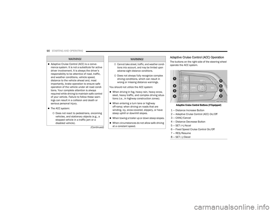
The buttons on the right side of the steering wheel
operate the ACC system.
Adaptive Cruise Control Buttons (If Equipped)
WARNING!
’ü¼Adaptive Cruise Control (ACC) is a conve -
nience system. It is not a substitute for active
driver involvement. It is always the driverŌĆÖs
responsibility to be attentive of road, traffic,
and weather conditions, vehicle speed,
distance to the vehicle ahead and, most
importantly, brake operation to ensure safe
operation of the vehicle under all road condi -
tions. Your complete attention is always
required while driving to maintain safe control
of your vehicle. Failure to follow these warn -
ings can result in a collision and death or
serious personal injury.
’ü¼The ACC system:
’éĪDoes not react to pedestrians, oncoming
vehicles, and stationary objects (e.g., a
stopped vehicle in a traffic jam or a
disabled vehicle).
’éĪCannot take street, traffic, and weather condi -
tions into account, and may be limited upon
adverse sight distance conditions.
’éĪDoes not always fully recognize complex
driving conditions, which can result in
wrong or missing distance warnings.
You should not utilize the ACC system:
’ü¼When driving in fog, heavy rain, heavy snow,
sleet, heavy traffic, and complex driving situa -
tions (i.e., in highway construction zones).
’ü¼When entering a turn lane or highway
off-ramp; when driving on roads that are
winding, icy, snow-covered, slippery, or have
steep uphill or downhill slopes.
’ü¼When towing a trailer up or down steep slopes.
’ü¼When circumstances do not allow safe driving
at a constant speed.
WARNING!
1 ŌĆö Distance Increase Button
2 ŌĆö Adaptive Cruise Control (ACC) On/Off
3 ŌĆö CANC/Cancel
4 ŌĆö Distance Decrease Button
5 ŌĆö SET (+)/Accel
6 ŌĆö Fixed Speed Cruise Control On/Off
7 ŌĆö RES/Resume
8 ŌĆö SET (-)/Decel
23_VF_OM_EN_USC_t.book Page 90
Page 96 of 296
94STARTING AND OPERATING
When ACC Is Active
’ü¼When you use the SET
(-)
button to decelerate, if the
engineŌĆÖs braking power does not slow the vehicle
sufficiently to reach the set speed, the brake system
will automatically slow the vehicle.
’ü¼The ACC system decelerates the vehicle to a full
stop when following the vehicle in front. If your
vehicle follows the vehicle in front to a standstill,
after two seconds the driver will either have to
push the RES (resume) button, or apply the
accelerator pedal to reengage the ACC to the
existing set speed.
’ü¼The ACC system maintains set speed when
driving uphill and downhill. However, a slight
speed change on moderate hills is normal.
In addition, downshifting may occur while
climbing uphill or descending downhill. This is
normal operation and necessary to maintain set
speed. When driving uphill and downhill, the
ACC system will cancel if the braking tempera -
ture exceeds normal range (overheated).
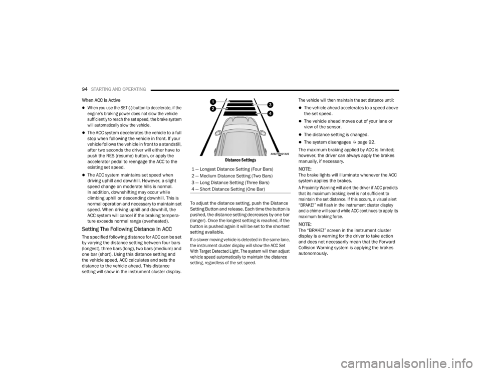
Setting The Following Distance In ACC
The specified following distance for ACC can be set
by varying the distance setting between four bars
(longest), three bars (long), two bars (medium) and
one bar (short). Using this distance setting and
the vehicle speed, ACC calculates and sets the
distance to the vehicle ahead. This distance
setting will show in the instrument cluster display.
Distance Settings
To adjust the distance setting, push the Distance
Setting Button and release. Each time the button is
pushed, the distance setting decreases by one bar
(longer). Once the longest setting is reached, if the
button is pushed again it will be set to the shortest
setting available.
If a slower moving vehicle is detected in the same lane,
the instrument cluster display will show the ACC Set
With Target Detected Light. The system will then adjust
vehicle speed automatically to maintain the distance
setting, regardless of the set speed. The vehicle will then maintain the set distance until:
’ü¼The vehicle ahead accelerates to a speed above
the set speed.
’ü¼The vehicle ahead moves out of your lane or
view of the sensor.
’ü¼The distance setting is changed.
’ü¼The system disengages ├Ü
page 92.
The maximum braking applied by ACC is limited;
however, the driver can always apply the brakes
manually, if necessary.
NOTE:The brake lights will illuminate whenever the ACC
system applies the brakes.
A Proximity Warning will alert the driver if ACC predicts
that its maximum braking level is not sufficient to
maintain the set distance. If this occurs, a visual alert
ŌĆ£BRAKE!ŌĆØ will flash in the instrument cluster display
and a chime will sound while ACC continues to apply its
maximum braking force.
NOTE:The ŌĆ£BRAKE!ŌĆØ screen in the instrument cluster
display is a warning for the driver to take action
and does not necessarily mean that the Forward
Collision Warning system is applying the brakes
autonomously.
1 ŌĆö Longest Distance Setting (Four Bars)
2 ŌĆö Medium Distance Setting (Two Bars)
3 ŌĆö Long Distance Setting (Three Bars)
4 ŌĆö Short Distance Setting (One Bar)
23_VF_OM_EN_USC_t.book Page 94
Page 97 of 296

STARTING AND OPERATING95
Overtake Aid
When driving with Adaptive Cruise Control (ACC)
engaged and following a vehicle, the system will
provide an additional acceleration up to the ACC
set speed to assist in passing the vehicle. This
additional acceleration is triggered when the driver
utilizes the left turn signal and will only be active
when passing on the left hand side.
ACC Operation At Stop
In the event that the ACC system brings your
vehicle to a standstill while following a vehicle in
front, if the vehicle in front starts moving within two
seconds of your vehicle coming to a standstill, your
vehicle will resume motion without the need for
any driver action.
If the vehicle in front does not start moving within
two seconds of your vehicle coming to a standstill,
the driver will either have to push the RES (resume)
button, or apply the accelerator pedal to reengage
the ACC to the existing set speed.
NOTE:After the ACC system holds your vehicle at a stand -
still for approximately three consecutive minutes,
the parking brake will be activated, and the ACC
system will be canceled.
While ACC is holding your vehicle at a standstill, if
the driver tries to leave the vehicle, the parking
brake will be activated and the ACC system will be
canceled.
Display Warnings And Maintenance
RADAR SENSOR UNAVAILABILITY WARNING
The ŌĆ£ACC Front Radar Sensor Temporarily BlindedŌĆØ
warning will display and a chime will sound when
conditions temporarily limit system performance.
This most often occurs at times of poor visibility,
such as in snow or heavy rain. The ACC system
may also become temporarily blinded due to
obstructions, such as mud, dirt or ice. In these
cases, the instrument cluster display will display
this warning message and the system will
deactivate.
This message can sometimes be displayed while
driving in highly reflective areas (i.e. ice and snow,
or tunnels with reflective tiles). The ACC system will
recover after the vehicle has left these areas.
Under rare conditions, when the radar is not
tracking any vehicles or objects in its path this
warning may temporarily occur.
NOTE:If the ŌĆ£ACC Front Radar Sensor Temporarily
BlindedŌĆØ warning is active, Fixed Speed Cruise
Control can be still enabled.
If weather conditions are not a factor, the driver
should examine the sensor. It may require cleaning
or removal of an obstruction. The sensor is located
in the center of the vehicle behind the lower grille.
To keep the ACC system operating properly, it is
important to note the following maintenance
items:
’ü¼Always keep the sensor clean. Carefully wipe the
sensor lens with a soft cloth. Be cautious not to
damage the sensor lens.
’ü¼Do not remove any screws from the sensor.
Doing so could cause an ACC system malfunc -
tion or failure and require a sensor realignment.
’ü¼If the sensor or front end of the vehicle is
damaged due to a collision, see an authorized
dealer for service.
’ü¼Do not attach or install any accessories near the
sensor, including transparent material or after -
market grilles. Doing so could cause an ACC
system failure or malfunction.
When the condition that deactivated the system is
no longer present, the system will return to the
ŌĆ£Adaptive Cruise Control OffŌĆØ state and will resume
function by simply reactivating it.
WARNING!
When the ACC system is resumed, the driver
must ensure that there are no pedestrians,
vehicles or objects in the path of the vehicle.
Failure to follow these warnings can result in a
collision and death or serious personal injury.
4
23_VF_OM_EN_USC_t.book Page 95
Page 122 of 296

120STARTING AND OPERATING
NOTE:
If snow, ice, mud, or any foreign substance builds up
on the camera lens, clean the lens, rinse with water,
and dry with a soft cloth. Do not cover the lens.
SURROUND VIEW CAMERA SYSTEM ŌĆö
IF EQUIPPED
Your vehicle may be equipped with the Surround View
Camera system that allows you to see an on-screen
image of the surroundings and Top View of your vehicle
whenever the gear selector is put into REVERSE or a
different view is selected through the touchscreen
buttons. The Top View of the vehicle will show which
doors are open. The image will be displayed on the
touchscreen display along with a caution note ŌĆ£Check
Entire SurroundingsŌĆØ across the top of the screen. After five seconds, this note will disappear. The Surround
View Camera system is comprised of four sequential
cameras located in the front grille, rear Center High
Mounted Stop Lamp (CHMSL), and side mirrors.
NOTE:The Surround View Camera system has program
-
mable settings that may be selected through the
Uconnect system Ú page 134.
When the vehicle is shifted into REVERSE, the Rear
View and Top View is the default view of the
system.
When the vehicle is shifted out of REVERSE with
camera delay turned on, the camera image will
continue to be displayed for up to 10 seconds unless
the vehicle speed exceeds 8 mph (13 km/h), the
vehicle is shifted into PARK, or the ignition is placed in
the OFF position. There is a touchscreen X button to
disable the display of the camera image.
When the vehicle is shifted out of REVERSE with
camera delay turned off, the Surround View system
is exited and the last known screen appears again.
Whenever the Rear View Camera image is
activated through the Back Up Camera button
in the Controls menu, and the vehicle speed is
greater than, or equal to, 8 mph (13 km/h), a
display timer for the image is initiated. The image
will continue to be displayed until the display timer
exceeds 10 seconds.
NOTE:
’ü¼If the vehicle speed remains below 8 mph
(13 km/h), the Rear View Camera image will
be displayed continuously until deactivated via
the touchscreen X button, the transmission is
shifted into PARK, or the ignition is placed in the
OFF position.
’ü¼The touchscreen X button to disable display of
the camera image is made available ONLY when
the vehicle is not in REVERSE.
When enabled, active guidelines are overlaid on
the image to illustrate the width of the vehicle,
including the side view mirrors and its projected
back up path based on the steering wheel position.
Different colored zones indicate the distance to
the rear of the vehicle.
The following table shows the approximate
distances for each zone:
CAUTION!
’ü¼To avoid vehicle damage, ParkView should
only be used as a parking aid. The ParkView
camera is unable to view every obstacle or
object in your drive path.
’ü¼To avoid vehicle damage, the vehicle must be
driven slowly when using ParkView to be able
to stop in time when an obstacle is seen. It is
recommended that the driver look frequently
over his/her shoulder when using ParkView.
Zone Distance To The Rear Of The
Vehicle
Red 0 - 1 ft (0 - 30 cm)
Yellow 1 ft - 6.5 ft (30 cm - 2 m) Green 6.5 ft or greater (2 m or greater)
23_VF_OM_EN_USC_t.book Page 120