ESP Ram ProMaster City 2018 Owner's Manual
[x] Cancel search | Manufacturer: RAM, Model Year: 2018, Model line: ProMaster City, Model: Ram ProMaster City 2018Pages: 180, PDF Size: 7.52 MB
Page 62 of 180
NOTE:
• Air bag covers may not be obvious in theinterior trim, but they will open during air
bag deployment.
• After any collision, the vehicle should be taken to an authorized dealer immediately.
Enhanced Accident Response System
In the event of an impact, if the communica-
tion network remains intact, and the power
remains intact, depending on the nature of
the event, the ORC will determine whether to
have the Enhanced Accident Response Sys-
tem perform the following functions:
• Cut off fuel to the engine.
• Flash hazard lights as long as the batteryhas power or until the hazard light button is
pressed. The hazard lights can be deacti-
vated by pressing the hazard light button.
• Turn on the interior lights, which remain on as long as the battery has power or for
15 minutes from the intervention of the
Enhanced Accident Response System.
• Unlock the power door locks.
Enhanced Accident Response System Reset
Procedure
In order to reset the Enhanced Accident Re-
sponse System functions after an event, the
ignition switch must be changed from igni-
tion START or ON/RUN to ignition OFF. Care-
fully check the vehicle for fuel leaks in the
engine compartment and on the ground near
the engine compartment and fuel tank before
resetting the system and starting the engine.
Maintaining Your Air Bag System
WARNING!
• Modifications to any part of the air bag system could cause it to fail when you
need it. You could be injured if the air
bag system is not there to protect you.
Do not modify the components or wiring,
including adding any kind of badges or
stickers to the steering wheel hub trim
cover or the upper right side of the
instrument panel. Do not modify the
front bumper, vehicle body structure, or
add aftermarket side steps or running
boards.
WARNING!
• It is dangerous to try to repair any part ofthe air bag system yourself. Be sure to
tell anyone who works on your vehicle
that it has an air bag system.
• Do not attempt to modify any part of your
air bag system. The air bag may inflate
accidentally or may not function prop-
erly if modifications are made. Take your
vehicle to an authorized dealer for any
air bag system service. If your seat, in-
cluding your trim cover and cushion,
needs to be serviced in any way (includ-
ing removal or loosening/tightening of
seat attachment bolts), take the vehicle
to your authorized dealer. Only manufac-
turer approved seat accessories may be
used. If it is necessary to modify the air
bag system for persons with disabilities,
contact your authorized dealer.
SAFETY
60
Page 85 of 180
The Rear Back Up Camera can also be acti-
vated when the vehicle is not in REVERSE
through the Uconnect System. Refer to
“Uconnect 3/3 NAV With 5-inch Display”
supplement for further information.
NOTE:
If one of the rear cargo doors is not com-
pletely closed, the Back Up Camera cannot
provide an accurate image of the area behind
the vehicle. A dedicated message will appear
on the Uconnect display indicating the cam-
era is not in the correct position.The Camera Delay setting can be set to on/off
in the rear camera settings menu. When the
vehicle is shifted out of REVERSE and the
Camera Delay is turned off, the rear camera
mode is exited and the navigation or audio
screen appears on display again.
When the transmission is shifted out of RE-
VERSE, and Camera Delay is activated in the
menu screen, the camera image will continue
to be displayed for up to 10 seconds, unless
the speed of the vehicle is greater than 8 mph
(13 km/h), the transmission is in PARK, or
the ignition key is in the OFF position.The display of the camera image can be
enabled or disabled through the rear camera
setting menu item (Camera on/off).
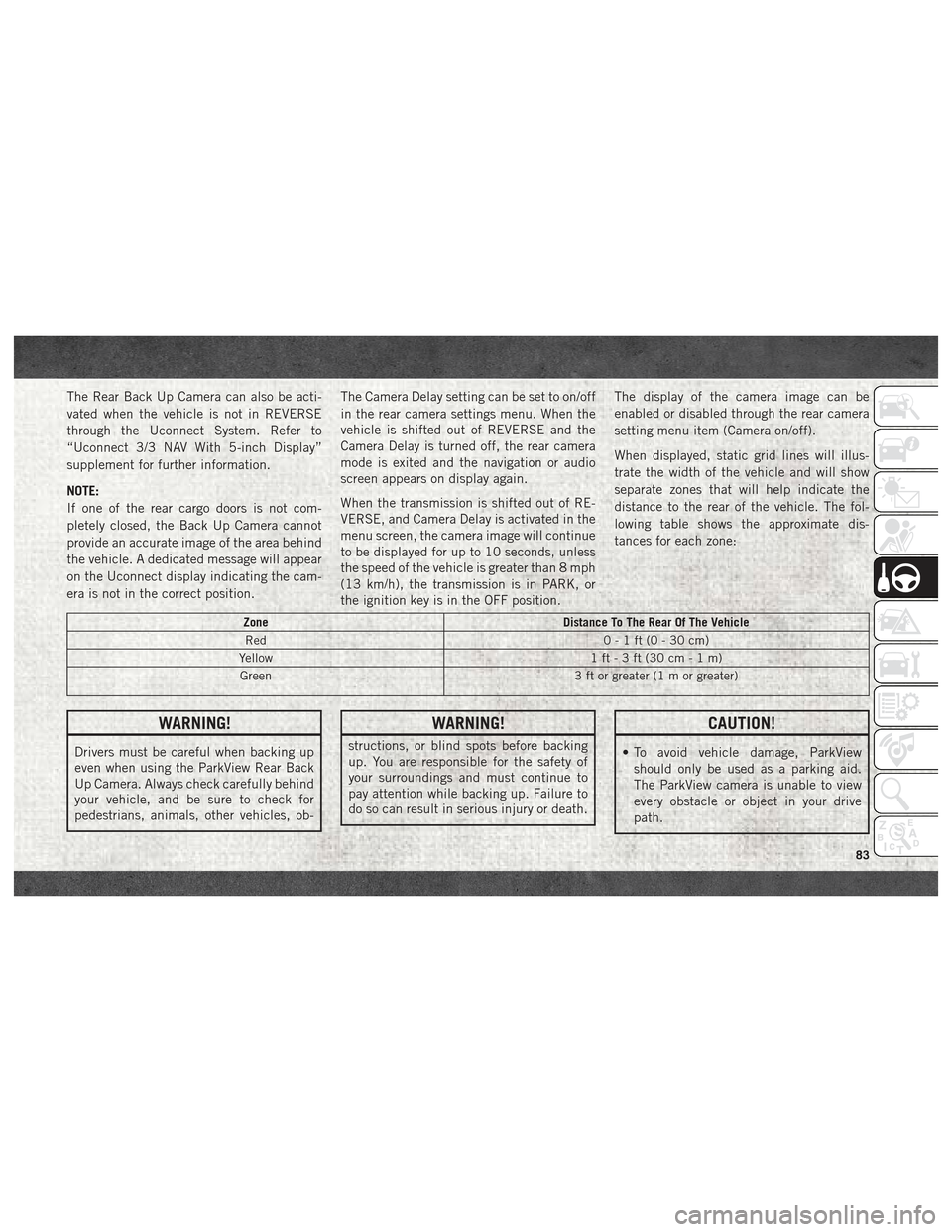
When displayed, static grid lines will illus-
trate the width of the vehicle and will show
separate zones that will help indicate the
distance to the rear of the vehicle. The fol-
lowing table shows the approximate dis-
tances for each zone:
Zone
Distance To The Rear Of The Vehicle
Red 0-1ft(0-30cm)
Yellow 1 ft - 3 ft (30 cm - 1 m)
Green 3 ft or greater (1 m or greater)
WARNING!
Drivers must be careful when backing up
even when using the ParkView Rear Back
Up Camera. Always check carefully behind
your vehicle, and be sure to check for
pedestrians, animals, other vehicles, ob-
WARNING!
structions, or blind spots before backing
up. You are responsible for the safety of
your surroundings and must continue to
pay attention while backing up. Failure to
do so can result in serious injury or death.
CAUTION!
• To avoid vehicle damage, ParkView
should only be used as a parking aid.
The ParkView camera is unable to view
every obstacle or object in your drive
path.
83
Page 89 of 180
IN CASE OF EMERGENCY
BULB REPLACEMENT............88
Replacement Bulbs..............88
FUSES......................89
Underhood Fuses ...............89
Interior Fuses .................91
Central Unit Fuse Panel ...........92
JACKING AND TIRE CHANGING ......92
Jack Location.................93
Removing The Spare Tire ..........93
Preparations For Jacking ..........95Jacking Instructions
.............95
Vehicles With Alloy Wheels .........98
Vehicles Equipped With Wheel Covers. . .99
TIRE SERVICE KIT — IF EQUIPPED . .100
Tire Service Kit Storage ..........100
Tire Service Kit Usage ...........100
JUMP STARTING..............102
Preparations For Jump Starting ......102
Jump Starting Procedure ..........103
IGNITION KEY REMOVAL OVERRIDE . . .104 GEAR SELECTOR OVERRIDE
.......105
IF YOUR ENGINE OVERHEATS ......106
FREEING A STUCK VEHICLE .......106
TOWING A DISABLED VEHICLE .....108
ENHANCED ACCIDENT RESPONSE
SYSTEM (EARS) ...............108
EVENT DATA RECORDER (EDR) ......108
IN CASE OF EMERGENCY
87
Page 91 of 180

FUSES
WARNING!
• When replacing a blown fuse, always usean appropriate replacement fuse with
the same amp rating as the original fuse.
Never replace a fuse with another fuse of
higher amp rating. Never replace a
blown fuse with metal wires or any other
material. Do not place a fuse inside a
circuit breaker cavity or vice versa. Fail-
ure to use proper fuses may result in
WARNING!
serious personal injury, fire and/or prop-
erty damage.
• Before replacing a fuse, make sure that
the ignition is off and that all the other
services are switched off and/or disen-
gaged.
• If the replaced fuse blows again, contact
an authorized dealer.
• If a general protection fuse for safety
systems (air bag system, braking sys-
tem), power unit systems (engine sys-
tem, transmission system) or steering
WARNING!
system blows, contact an authorized
dealer.
Underhood Fuses
The Front Distribution Unit is located on the
right side of the engine compartment, next to
the battery. To access the fuses, remove fas-
teners and remove the cover.
The ID number of the electrical component
corresponding to each fuse can be found on
the back of the cover.
Cavity Maxi Fuse Mini Fuse Description
F01 60 Amp Blue –Body Controller
F02 40 Amp Orange –Rear Power Windows, Fog Lamps, Front Heated Seats
(If Equipped)
F02 30 Amp Green –Rear Power Windows, Front Heated Seats (If
Equipped)
F02 30 Amp Green –Fog Lamps, Front Heated Seats (If Equipped)
F02 20 Amp Yellow –Front Heated Seats
F03 20 Amp Yellow –Ignition Switch
F04 40 Amp Orange –BSM System Module
F06 20 Amp Yellow –Radiator Fan - Low Speed
89
Page 103 of 180
WARNING!
stow the Tire Service Kit in the place
provided. Failure to follow these warn-
ings can result in injuries that are seri-
ous or fatal to you, your passengers, and
others around you.
• Take care not to allow the contents of
Tire Service Kit to come in contact with
hair, eyes, or clothing. Tire Service Kit
sealant is harmful if inhaled, swallowed,
or absorbed through the skin. It causes
skin, eye, and respiratory irritation.
Flush immediately with plenty of water if
there is any contact with eyes or skin.
Change clothing as soon as possible, if
there is any contact with clothing.
• Tire Service Kit Sealant solution con-
tains latex. In case of an allergic reac-
tion or rash, consult a physician imme-
diately. Keep Tire Service Kit out of
reach of children. If swallowed, rinse
mouth immediately with plenty of water
and drink plenty of water. Do not induce
vomiting! Consult a physician immedi-
ately. Insert the power plug into the vehicle power
outlet socket. Start the vehicle engine.
Push the Tire Service Kit power button to the
“I” position. The electric compressor will be
turned on, sealant and air will inflate the tire.
Minimum 26 psi (1.8 bar) of pressure should
be reached within 20 minutes. If the pressure
has not been reached, turn off and remove
the Tire Service Kit, drive the vehicle 30 feet
(10 meters) back and forth, to better distrib-
ute the sealant inside the tire.
Attach the clear flexible filling tube of the
compressor directly to the tire valve and re-
peat the inflation process.
When the correct pressure has been reached,
start driving the vehicle to uniformly distrib-
ute the sealant inside the tire. After 10 min-
utes, stop and check the tire pressure. If the
pressure is below 19 psi (1.3 bar), do not
drive the vehicle, as the tire is too damaged,
contact the nearest authorized dealer.
WARNING!
Tire Service Kit is not a permanent flat tire
repair. Have the tire inspected and re-
paired or replaced after using Tire Service
Kit. Do not exceed 65 mph (110 km/h)
until the tire is repaired or replaced. Fail-
ure to follow this warning can result in
injuries that are serious or fatal to you,
your passengers, and others around you.
Have the tire checked as soon as possible
at an authorized dealer.
If the pressure is at 19 psi (1.3 bar) or above
repeat the inflation process to reach the cor-
rect tire pressure and continue driving.
Peel off the warning label from the bottle and
place it on the dashboard as a reminder to the
driver that a tire has been treated with Tire
Service Kit.
WARNING!
The metal end fitting from Power Plug may
get hot after use, so it should be handled
carefully.
101
Page 110 of 180
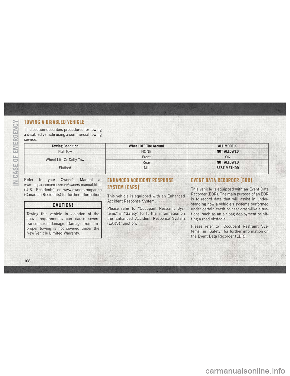
TOWING A DISABLED VEHICLE
This section describes procedures for towing
a disabled vehicle using a commercial towing
service.
Towing ConditionWheel OFF The Ground ALL MODELS
Flat Tow NONENOT ALLOWED
Wheel Lift Or Dolly Tow Front
OK
Rear NOT ALLOWED
Flatbed ALL
BEST METHOD
Refer to your Owner’s Manual at
www.mopar.com/en-us/care/owners-manual.html
(U.S. Residents) or www.owners.mopar.ca
(Canadian Residents) for further information.
CAUTION!
Towing this vehicle in violation of the
above requirements can cause severe
transmission damage. Damage from im-
proper towing is not covered under the
New Vehicle Limited Warranty.
ENHANCED ACCIDENT RESPONSE
SYSTEM (EARS)
This vehicle is equipped with an Enhanced
Accident Response System.
Please refer to “Occupant Restraint Sys-
tems” in “Safety” for further information on
the Enhanced Accident Response System
(EARS) function.
EVENT DATA RECORDER (EDR)
This vehicle is equipped with an Event Data
Recorder (EDR). The main purpose of an EDR
is to record data that will assist in under-
standing how a vehicle’s systems performed
under certain crash or near crash-like situa-
tions, such as an air bag deployment or hit-
ting a road obstacle.
Please refer to “Occupant Restraint Sys-
tems” in “Safety” for further information on
the Event Data Recorder (EDR).IN CASE OF EMERGENCY
108
Page 119 of 180

EXAMPLE:
Service Description:
95 = Load Index
• A numerical code associated with the maximum load a tire can carry
H = Speed Symbol
• A symbol indicating the range of speeds at which a tire can carry a load corresponding to its load index under certain operating conditions
• The maximum speed corresponding to the speed symbol should only be achieved under specified operating conditions (i.e., tire pressure, vehicle
loading, road conditions, and posted speed limits)
Load Identification:
Absence of the following load identification symbols on the sidewall of the tire indicates a Standard Load (SL) tire:
• XL= Extra load (or reinforced) tire, or
• LL= Light load tire or
• C, D, E, F, G = Load range associated with the maximum load a tire can carry at a specified pressure
Maximum Load – Maximum load indicates the maximum load this tire is designed to carry
Maximum Pressure – Maximum pressure indicates the maximum permissible cold tire inflation pressure for this tire
117
Page 125 of 180
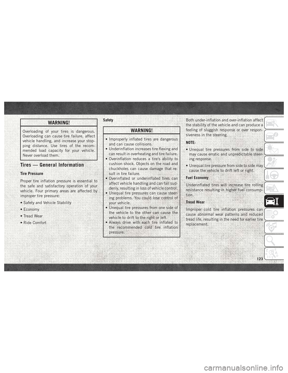
WARNING!
Overloading of your tires is dangerous.
Overloading can cause tire failure, affect
vehicle handling, and increase your stop-
ping distance. Use tires of the recom-
mended load capacity for your vehicle.
Never overload them.
Tires — General Information
Tire Pressure
Proper tire inflation pressure is essential to
the safe and satisfactory operation of your
vehicle. Four primary areas are affected by
improper tire pressure:
• Safety and Vehicle Stability
• Economy
• Tread Wear
• Ride ComfortSafety
WARNING!
• Improperly inflated tires are dangerous
and can cause collisions.
• Underinflation increases tire flexing and
can result in overheating and tire failure.
• Overinflation reduces a tire's ability to cushion shock. Objects on the road and
chuckholes can cause damage that re-
sult in tire failure.
• Overinflated or underinflated tires can
affect vehicle handling and can fail sud-
denly, resulting in loss of vehicle control.
• Unequal tire pressures can cause steer-
ing problems. You could lose control of
your vehicle.
• Unequal tire pressures from one side of
the vehicle to the other can cause the
vehicle to drift to the right or left.
• Always drive with each tire inflated to
the recommended cold tire inflation
pressure. Both under-inflation and over-inflation affect
the stability of the vehicle and can produce a
feeling of sluggish response or over respon-
siveness in the steering.
NOTE:
• Unequal tire pressures from side to side
may cause erratic and unpredictable steer-
ing response.
• Unequal tire pressure from side to side may cause the vehicle to drift left or right.
Fuel Economy
Underinflated tires will increase tire rolling
resistance resulting in higher fuel consump-
tion.
Tread Wear
Improper cold tire inflation pressures can
cause abnormal wear patterns and reduced
tread life, resulting in the need for earlier tire
replacement.
123
Page 126 of 180
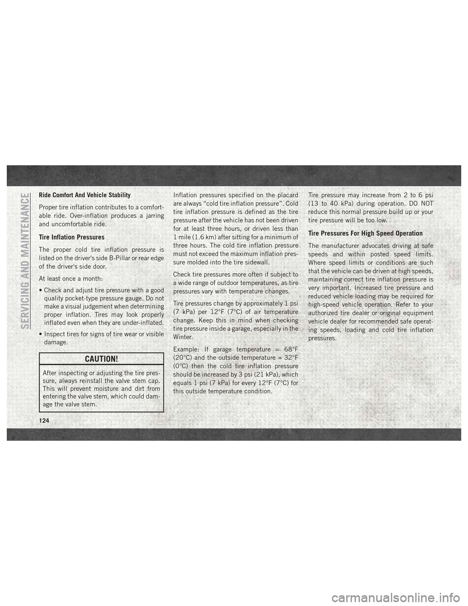
Ride Comfort And Vehicle Stability
Proper tire inflation contributes to a comfort-
able ride. Over-inflation produces a jarring
and uncomfortable ride.
Tire Inflation Pressures
The proper cold tire inflation pressure is
listed on the driver's side B-Pillar or rear edge
of the driver's side door.
At least once a month:
• Check and adjust tire pressure with a goodquality pocket-type pressure gauge. Do not
make a visual judgement when determining
proper inflation. Tires may look properly
inflated even when they are under-inflated.
• Inspect tires for signs of tire wear or visible damage.
CAUTION!
After inspecting or adjusting the tire pres-
sure, always reinstall the valve stem cap.
This will prevent moisture and dirt from
entering the valve stem, which could dam-
age the valve stem. Inflation pressures specified on the placard
are always “cold tire inflation pressure”. Cold
tire inflation pressure is defined as the tire
pressure after the vehicle has not been driven
for at least three hours, or driven less than
1 mile (1.6 km) after sitting for a minimum of
three hours. The cold tire inflation pressure
must not exceed the maximum inflation pres-
sure molded into the tire sidewall.
Check tire pressures more often if subject to
a wide range of outdoor temperatures, as tire
pressures vary with temperature changes.
Tire pressures change by approximately 1 psi
(7 kPa) per 12°F (7°C) of air temperature
change. Keep this in mind when checking
tire pressure inside a garage, especially in the
Winter.
Example: If garage temperature = 68°F
(20°C) and the outside temperature = 32°F
(0°C) then the cold tire inflation pressure
should be increased by 3 psi (21 kPa), which
equals 1 psi (7 kPa) for every 12°F (7°C) for
this outside temperature condition.
Tire pressure may increase from 2 to 6 psi
(13 to 40 kPa) during operation. DO NOT
reduce this normal pressure build up or your
tire pressure will be too low.
Tire Pressures For High Speed Operation
The manufacturer advocates driving at safe
speeds and within posted speed limits.
Where speed limits or conditions are such
that the vehicle can be driven at high speeds,
maintaining correct tire inflation pressure is
very important. Increased tire pressure and
reduced vehicle loading may be required for
high-speed vehicle operation. Refer to your
authorized tire dealer or original equipment
vehicle dealer for recommended safe operat-
ing speeds, loading and cold tire inflation
pressures.
SERVICING AND MAINTENANCE
124
Page 132 of 180

WARNING!
Compact and Collapsible spares are for
temporary emergency use only. With these
spares, do not drive more than 50 mph
(80 km/h). Temporary use spares have
limited tread life. When the tread is worn
to the tread wear indicators, the temporary
use spare tire needs to be replaced. Be
sure to follow the warnings, which apply to
your spare. Failure to do so could result in
spare tire failure and loss of vehicle con-
trol.
Full Size Spare — If Equipped
The full size spare is for temporary emer-
gency use only. This tire may look like the
originally equipped tire on the front or rear
axle of your vehicle, but it is not. This spare
tire may have limited tread life. When the
tread is worn to the tread wear indicators, the
temporary use full size spare tire needs to be
replaced. Since it is not the same as your
original equipment tire, replace (or repair)
the original equipment tire and reinstall on
the vehicle at the first opportunity.
Limited Use Spare — If Equipped
The limited use spare tire is for temporary
emergency use only. This tire is identified by
a label located on the limited use spare
wheel. This label contains the driving limita-
tions for this spare. This tire may look like the
original equipped tire on the front or rear axle
of your vehicle, but it is not. Installation of
this limited use spare tire affects vehicle
handling. Since it is not the same as your
original equipment tire, replace (or repair)
the original equipment tire and reinstall on
the vehicle at the first opportunity.
WARNING!
Limited use spares are for emergency use
only. Installation of this limited use spare
tire affects vehicle handling. With this tire,
do not drive more than the speed listed on
the limited use spare wheel. Keep inflated
to the cold tire inflation pressures listed on
your Tire and Loading Information Placard
located on the driver’s side B-Pillar or the
rear edge of the driver’s side door. Replace
(or repair) the original equipment tire at
the first opportunity and reinstall it on your
WARNING!
vehicle. Failure to do so could result in
loss of vehicle control.
Wheel And Wheel Trim Care
All wheels and wheel trim, especially alumi-
num and chrome plated wheels, should be
cleaned regularly using mild (neutral Ph)
soap and water to maintain their luster and to
prevent corrosion. Wash wheels with the
same soap solution recommended for the
body of the vehicle.
Your wheels are susceptible to deterioration
caused by salt, sodium chloride, magnesium
chloride, calcium chloride, etc., and other
road chemicals used to melt ice or control
dust on dirt roads. Use a soft cloth or sponge
and mild soap to wipe away promptly. Do not
use harsh chemicals or a stiff brush. They
can damage the wheel’s protective coating
that helps keep them from corroding and
tarnishing.
SERVICING AND MAINTENANCE
130