technical specifications Ram ProMaster City 2018 User Guide
[x] Cancel search | Manufacturer: RAM, Model Year: 2018, Model line: ProMaster City, Model: Ram ProMaster City 2018Pages: 180, PDF Size: 7.52 MB
Page 5 of 180
GRAPHICAL TABLE OF CONTENTS
GETTING TO KNOW YOUR VEHICLE
GETTING TO KNOW YOUR INSTRUMENT PANEL SAFETY
STARTING AND OPERATING IN CASE OF EMERGENCY
SERVICING AND MAINTENANCE TECHNICAL SPECIFICATIONS MULTIMEDIA
CUSTOMER ASSISTANCE INDEX
Page 82 of 180
ENGINE BREAK-IN
RECOMMENDATIONS — GASOLINE
ENGINE
A long break-in period is not required for the
engine and drivetrain (transmission and axle)
in your vehicle.
Drive moderately during the first 300 miles
(500 km). After the initial 60 miles
(100 km), speeds up to 50 or 55 mph (80 or
90 km/h) are desirable.
While cruising, brief full-throttle acceleration
within the limits of local traffic laws contrib-
utes to a good break-in. Wide-open throttle
acceleration in low gear can be detrimental
and should be avoided.
The engine oil installed in the engine at the
factory is a high-quality energy conserving
type lubricant. Oil changes should be consis-
tent with anticipated climate conditions un-
der which vehicle operations will occur. For
the recommended viscosity and quality
grades, refer to “Fluids And Lubricants” in
“Technical Specifications”.
CAUTION!
Never use Non-Detergent Oil or Straight
Mineral Oil in the engine or damage may
result.
NOTE:
A new engine may consume some oil during
its first few thousand miles (kilometers) of
operation. This should be considered a nor-
mal part of the break-in and not interpreted
as a problem. Please check your oil level with
the engine oil indicator often during the
break in period. Add oil as required.
SPEED CONTROL
When engaged, the Speed Control takes over
accelerator operations at speeds greater than
25 mph (40 km/h).
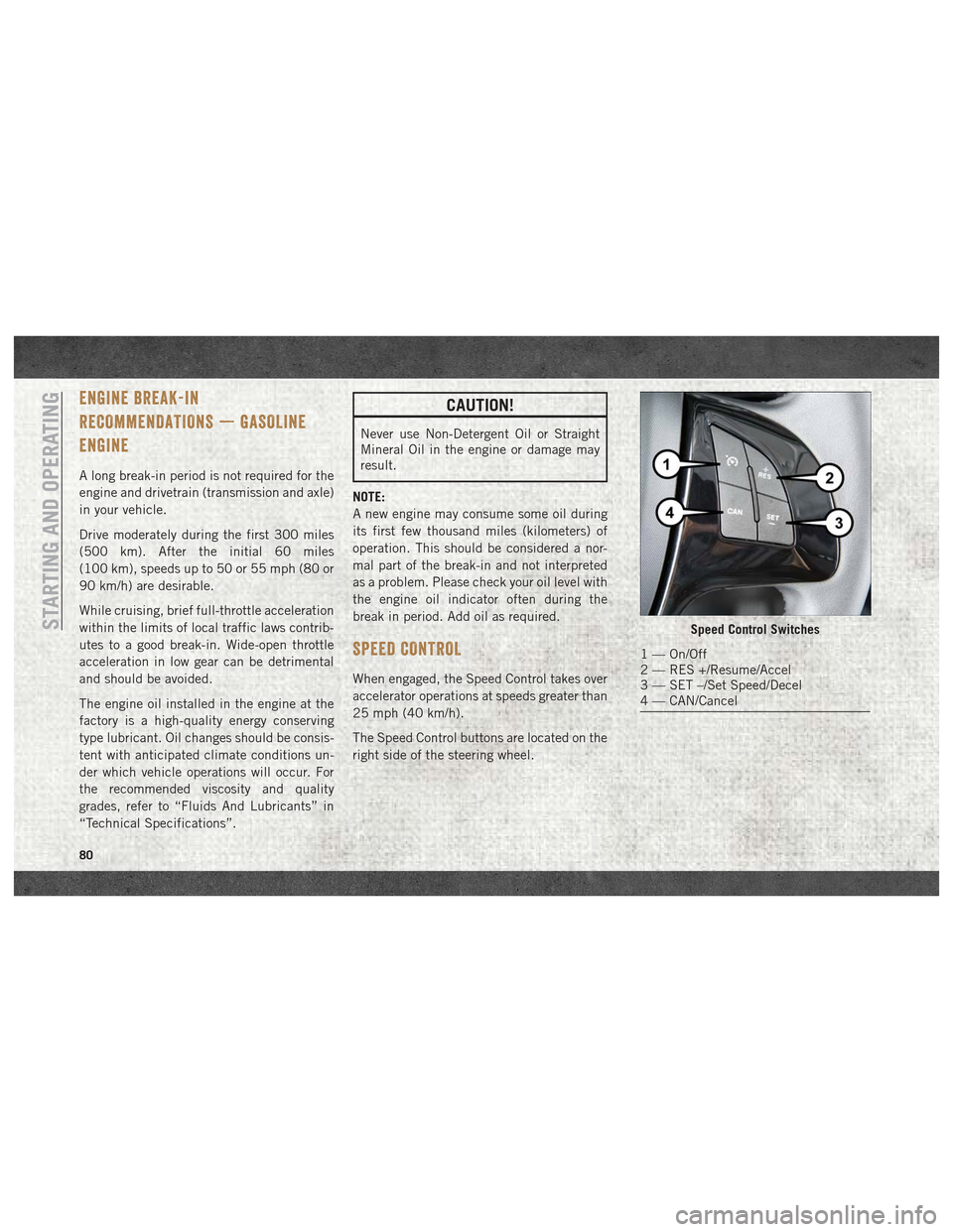
The Speed Control buttons are located on the
right side of the steering wheel.
Speed Control Switches
1 — On/Off
2 — RES +/Resume/Accel
3 — SET –/Set Speed/Decel
4 — CAN/Cancel
STARTING AND OPERATING
80
Page 100 of 180
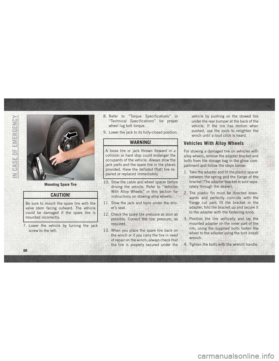
CAUTION!
Be sure to mount the spare tire with the
valve stem facing outward. The vehicle
could be damaged if the spare tire is
mounted incorrectly.
7. Lower the vehicle by turning the jack screw to the left. 8. Refer to “Torque Specifications” in
“Technical Specifications” for proper
wheel lug bolt torque.
9. Lower the jack to its fully-closed position.
WARNING!
A loose tire or jack thrown forward in a
collision or hard stop could endanger the
occupants of the vehicle. Always stow the
jack parts and the spare tire in the places
provided. Have the deflated (flat) tire re-
paired or replaced immediately.
10. Stow the cable and wheel spacer before driving the vehicle. Refer to “Vehicles
With Alloy Wheels” in this section for
instructions on stowing alloy wheels.
11. Stow the jack and tools under the driv- er’s seat.
12. Check the spare tire pressure as soon as possible. Correct the tire pressure, as
required.
13. When you place the spare tire back on the winch or if you carry the tire in need
of repair on the winch, always check that
the tire is properly secured under the vehicle by pushing on the stowed tire
under the rear bumper at the back of the
vehicle. If the tire has motion when
pushed, use the tools to retighten the
winch until a loud click is heard.
Vehicles With Alloy Wheels
For stowing a damaged tire on vehicles with
alloy wheels, remove the adapter bracket and
bolts from the storage bag in the glove com-
partment and follow the steps below:
1. Take the adapter and fit the plastic spacer
between the spring and the flange of the
bracket (The adapter bracket is sold sepa-
rately through the dealer).
2. The plastic fin must be directed down- wards and perfectly coincide with the
flange cut part; fit the bracket in the
adapter, fold the bracket up and secure it
to the adapter with the fastening knob.
3. Position the tire vertically and lay the mounted adapter on the inner part of the
rim, using the supplied bolts fasten the
wheel to the adapter using the bolt install
wrench.
4. Tighten the bolts with the wrench handle.
Mounting Spare Tire
IN CASE OF EMERGENCY
98
Page 101 of 180
5. Rotate the winch mechanism clockwiseuntil the wheel is properly stowed under
the vehicle and until the wench makes
three audible noises.
6. Reach underneath and shake tire by hand to confirm that it is secure. The tire should
not move. If the tire is still loose and/or
three audible noises are not heard, place
and secure damaged wheel into the ve-
hicle and seek dealer assistance for the
winch mechanism.
This is for temporary use only.
Vehicles Equipped With Wheel
Covers
1. Mount the road tire on the axle.
2. To ease the installation process for steel wheels with wheel covers, install two
wheel bolts on the wheel. Install the wheel
bolts with the threaded end of the bolt
toward the wheel. Lightly tighten the
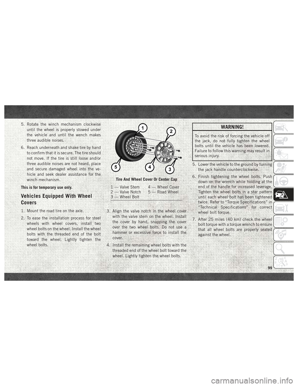
wheel bolts. 3. Align the valve notch in the wheel cover
with the valve stem on the wheel. Install
the cover by hand, snapping the cover
over the two wheel bolts. Do not use a
hammer or excessive force to install the
cover.
4. Install the remaining wheel bolts with the threaded end of the wheel bolt toward the
wheel. Lightly tighten the wheel bolts.
WARNING!
To avoid the risk of forcing the vehicle off
the jack, do not fully tighten the wheel
bolts until the vehicle has been lowered.
Failure to follow this warning may result in
serious injury.
5. Lower the vehicle to the ground by turning the jack handle counterclockwise.
6. Finish tightening the wheel bolts. Push down on the wrench while holding at the
end of the handle for increased leverage.
Tighten the wheel bolts in a star pattern
until each wheel bolt has been tightened
twice. Refer to “Torque Specifications” in
“Technical Specifications” for correct
wheel bolt torque.
7. After 25 miles (40 km) check the wheel bolt torque with a torque wrench to ensure
that all wheel bolts are properly seated
against the wheel.
Tire And Wheel Cover Or Center Cap
1 — Valve Stem 4 — Wheel Cover
2 — Valve Notch 5 — Road Wheel
3 — Wheel Bolt
99
Page 137 of 180

TECHNICAL SPECIFICATIONS
WHEEL AND TIRE TORQUE SPECIFICA-
TIONS.................... .136
Torque Specifications............136
FLUID CAPACITIES.............137
FLUIDS AND LUBRICANTS .........137
Engine.....................137 Chassis
....................138
MOPAR ACCESSORIES ...........139
Authentic Accessories By Mopar .....139
TECHNICAL SPECIFICATIONS
135
Page 138 of 180
WHEEL AND TIRE TORQUE
SPECIFICATIONS
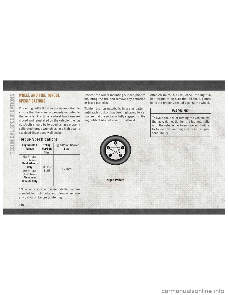
Proper lug nut/bolt torque is very important to
ensure that the wheel is properly mounted to
the vehicle. Any time a wheel has been re-
moved and reinstalled on the vehicle, the lug
nuts/bolts should be torqued using a properly
calibrated torque wrench using a high quality
six sided (hex) deep wall socket.
Torque Specifications
Lug Nut/BoltTorque **Lug
Nut/Bolt Size Lug Nut/Bolt Socket
Size
63 Ft-Lbs (86 N·m)
Steel Wheels
Only
89 Ft-Lbs
(120 N·m) Aluminum
Wheels Only M12 x
1.25 17 mm
**Use only your authorized dealer recom-
mended lug nuts/bolts and clean or remove
any dirt or oil before tightening. Inspect the wheel mounting surface prior to
mounting the tire and remove any corrosion
or loose particles.
Tighten the lug nuts/bolts in a star pattern
until each nut/bolt has been tightened twice.
Ensure that the socket is fully engaged on the
lug nut/bolt (do not insert it halfway).
After 25 miles (40 km), check the lug nut/
bolt torque to be sure that all the lug nuts/
bolts are properly seated against the wheel.
WARNING!
To avoid the risk of forcing the vehicle off
the jack, do not tighten the lug nuts fully
until the vehicle has been lowered. Failure
to follow this warning may result in per-
sonal injury.
Torque Pattern
TECHNICAL SPECIFICATIONS
136
Page 140 of 180
CAUTION!
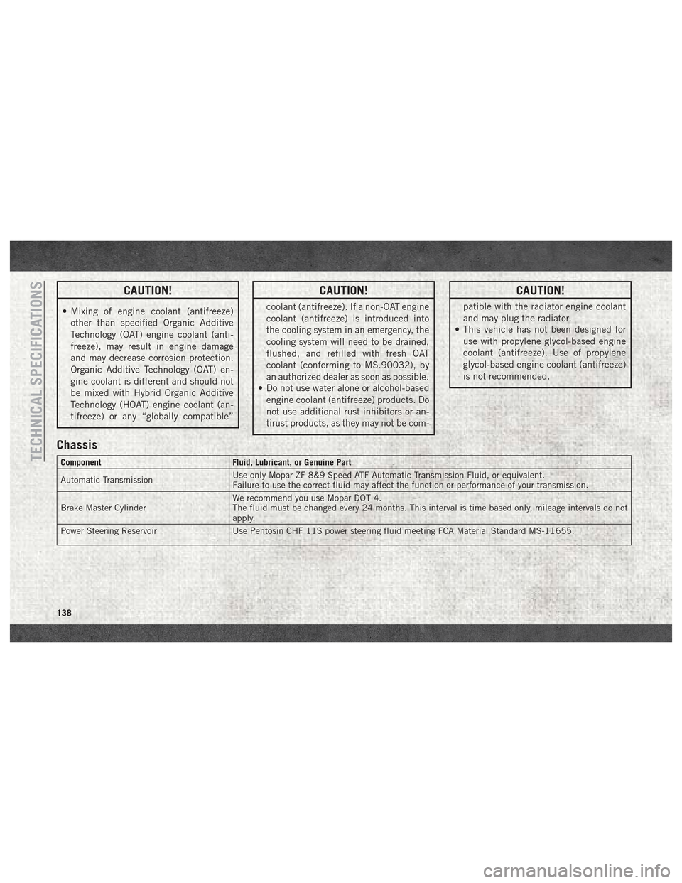
• Mixing of engine coolant (antifreeze)other than specified Organic Additive
Technology (OAT) engine coolant (anti-
freeze), may result in engine damage
and may decrease corrosion protection.
Organic Additive Technology (OAT) en-
gine coolant is different and should not
be mixed with Hybrid Organic Additive
Technology (HOAT) engine coolant (an-
tifreeze) or any “globally compatible”
CAUTION!
coolant (antifreeze). If a non-OAT engine
coolant (antifreeze) is introduced into
the cooling system in an emergency, the
cooling system will need to be drained,
flushed, and refilled with fresh OAT
coolant (conforming to MS.90032), by
an authorized dealer as soon as possible.
• Do not use water alone or alcohol-based
engine coolant (antifreeze) products. Do
not use additional rust inhibitors or an-
tirust products, as they may not be com-
CAUTION!
patible with the radiator engine coolant
and may plug the radiator.
• This vehicle has not been designed for
use with propylene glycol-based engine
coolant (antifreeze). Use of propylene
glycol-based engine coolant (antifreeze)
is not recommended.
Chassis
Component Fluid, Lubricant, or Genuine Part
Automatic Transmission Use only Mopar ZF 8&9 Speed ATF Automatic Transmission Fluid, or equivalent.
Failure to use the correct fluid may affect the function or performance of your transmission.
Brake Master Cylinder We recommend you use Mopar DOT 4.
The fluid must be changed every 24 months. This interval is time based only, mileage intervals do not
apply.
Power Steering Reservoir Use Pentosin CHF 11S power steering fluid meeting FCA Material Standard MS-11655.TECHNICAL SPECIFICATIONS
138