Air Ram ProMaster City 2018 Owner's Guide
[x] Cancel search | Manufacturer: RAM, Model Year: 2018, Model line: ProMaster City, Model: Ram ProMaster City 2018Pages: 180, PDF Size: 7.52 MB
Page 74 of 180
WARNING!
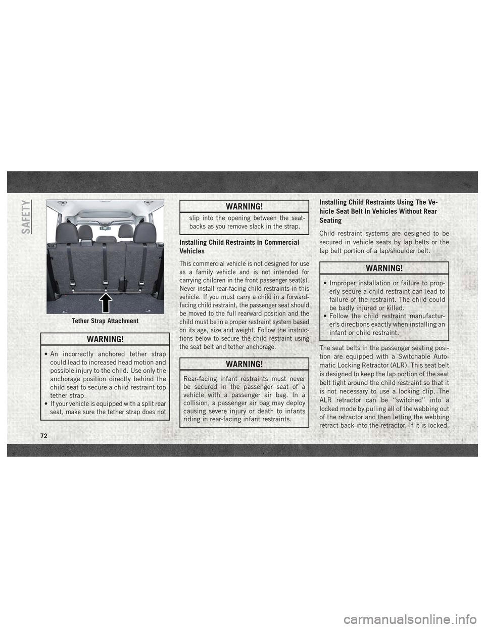
• An incorrectly anchored tether strapcould lead to increased head motion and
possible injury to the child. Use only the
anchorage position directly behind the
child seat to secure a child restraint top
tether strap.
•
If your vehicle is equipped with a split rear
seat, make sure the tether strap does not
WARNING!
slip into the opening between the seat-
backs as you remove slack in the strap.
Installing Child Restraints In Commercial
Vehicles
This commercial vehicle is not designed for use
as a family vehicle and is not intended for
carrying children in the front passenger seat(s).
Never install rear-facing child restraints in this
vehicle. If you must carry a child in a forward-
facing child restraint, the passenger seat should
be moved to the full rearward position and the
child must be in a proper restraint system based
on its age, size and weight. Follow the instruc-
tions below to secure the child restraint using
the seat belt and tether anchorage.
WARNING!
Rear-facing infant restraints must never
be secured in the passenger seat of a
vehicle with a passenger air bag. In a
collision, a passenger air bag may deploy
causing severe injury or death to infants
riding in rear-facing infant restraints.
Installing Child Restraints Using The Ve-
hicle Seat Belt In Vehicles Without Rear
Seating
Child restraint systems are designed to be
secured in vehicle seats by lap belts or the
lap belt portion of a lap/shoulder belt.
WARNING!
• Improper installation or failure to prop-
erly secure a child restraint can lead to
failure of the restraint. The child could
be badly injured or killed.
• Follow the child restraint manufactur-
er’s directions exactly when installing an
infant or child restraint.
The seat belts in the passenger seating posi-
tion are equipped with a Switchable Auto-
matic Locking Retractor (ALR). This seat belt
is designed to keep the lap portion of the seat
belt tight around the child restraint so that it
is not necessary to use a locking clip. The
ALR retractor can be “switched” into a
locked mode by pulling all of the webbing out
of the retractor and then letting the webbing
retract back into the retractor. If it is locked,
Tether Strap Attachment
SAFETY
72
Page 77 of 180

WARNING!
An incorrectly anchored tether strap could
lead to increased head motion and pos-
sible injury to the child. Use only the
anchorage position directly behind the
child seat to secure a child restraint top
tether strap.
Transporting Pets
Air Bags deploying in the front seat could
harm your pet. An unrestrained pet will be
thrown about and possibly injured, or injure a
passenger during panic braking or in a colli-
sion.
Pets should be restrained in the rear seat in
pet harnesses or pet carriers that are secured
by seat belts.
SAFETY TIPS
Transporting Passengers
NEVER TRANSPORT PASSENGERS IN THE
CARGO AREA.
WARNING!
• Do not leave children or animals insideparked vehicles in hot weather. Interior
heat build-up may cause serious injury
or death.
• It is extremely dangerous to ride in a
cargo area, inside or outside of a vehicle.
In a collision, people riding in these
areas are more likely to be seriously
injured or killed.
• Do not allow people to ride in any area of
your vehicle that is not equipped with
seats and seat belts.
• Be sure everyone in your vehicle is in a
seat and using a seat belt properly.
Exhaust Gas
WARNING!
Exhaust gases can injure or kill. They con-
tain carbon monoxide (CO), which is col-
orless and odorless. Breathing it can make
you unconscious and can eventually poi-
son you. To avoid breathing (CO), follow
these safety tips:
• Do not run the engine in a closed garageor in confined areas any longer than
needed to move your vehicle in or out of
the area.
• If you are required to drive with the
trunk/liftgate/rear doors open, make sure
that all windows are closed and the cli-
mate control BLOWER switch is set at
high speed. DO NOT use the recircula-
tion mode.
• If it is necessary to sit in a parked vehicle
with the engine running, adjust your
heating or cooling controls to force out-
side air into the vehicle. Set the blower
at high speed.
75
Page 78 of 180
The best protection against carbon monoxide
entry into the vehicle body is a properly
maintained engine exhaust system.
Whenever a change is noticed in the sound of
the exhaust system, when exhaust fumes can
be detected inside the vehicle, or when the
underside or rear of the vehicle is damaged,
have a competent mechanic inspect the com-
plete exhaust system and adjacent body ar-
eas for broken, damaged, deteriorated, or
mispositioned parts. Open seams or loose
connections could permit exhaust fumes to
seep into the passenger compartment. In
addition, inspect the exhaust system each
time the vehicle is raised for lubrication or oil
change. Replace as required.
Safety Checks You Should Make
Inside The Vehicle
Seat Belts
Inspect the seat belt system periodically,
checking for cuts, frays, and loose parts.
Damaged parts must be replaced immedi-
ately. Do not disassemble or modify the sys-
tem.Front seat belt assemblies must be replaced
after a collision. Rear seat belt assemblies
must be replaced after a collision if they have
been damaged (i.e., bent retractor, torn web-
bing, etc.). If there is any question regarding
seat belt or retractor condition, replace the
seat belt.
Air Bag Warning Light
The Air Bag warning lightwill turn on for
four to eight seconds as a bulb check when
the ignition switch is first turned to ON/RUN.
If the light is either not on during starting,
stays on, or turns on while driving, have the
system inspected at your authorized dealer as
soon as possible. After the bulb check, this
light will illuminate with a single chime when
a fault with the Air Bag System has been
detected. It will stay on until the fault is
cleared. If the light comes on intermittently
or remains on while driving, have your autho-
rized dealer service the vehicle immediately.
Refer to “Occupant Restraint Systems” in
“Safety” for further information.
Defroster
Check operation by selecting the defrost
mode and place the blower control on high
speed. You should be able to feel the air
directed against the windshield. See your
authorized dealer for service if your defroster
is inoperable.
Floor Mat Safety Information
Always use floor mats designed to fit your
vehicle. Only use a floor mat that does not
interfere with the operation of the accelera-
tor, brake or clutch pedals. Only use a floor
mat that is securely attached using the floor
mat fasteners so it cannot slip out of position
and interfere with the accelerator, brake or
clutch pedals or impair safe operation of your
vehicle in other ways.
WARNING!
An improperly attached, damaged, folded,
or stacked floor mat, or damaged floor mat
fasteners may cause your floor mat to
interfere with the accelerator, brake, or
SAFETY
76
Page 91 of 180

FUSES
WARNING!
• When replacing a blown fuse, always usean appropriate replacement fuse with
the same amp rating as the original fuse.
Never replace a fuse with another fuse of
higher amp rating. Never replace a
blown fuse with metal wires or any other
material. Do not place a fuse inside a
circuit breaker cavity or vice versa. Fail-
ure to use proper fuses may result in
WARNING!
serious personal injury, fire and/or prop-
erty damage.
• Before replacing a fuse, make sure that
the ignition is off and that all the other
services are switched off and/or disen-
gaged.
• If the replaced fuse blows again, contact
an authorized dealer.
• If a general protection fuse for safety
systems (air bag system, braking sys-
tem), power unit systems (engine sys-
tem, transmission system) or steering
WARNING!
system blows, contact an authorized
dealer.
Underhood Fuses
The Front Distribution Unit is located on the
right side of the engine compartment, next to
the battery. To access the fuses, remove fas-
teners and remove the cover.
The ID number of the electrical component
corresponding to each fuse can be found on
the back of the cover.
Cavity Maxi Fuse Mini Fuse Description
F01 60 Amp Blue –Body Controller
F02 40 Amp Orange –Rear Power Windows, Fog Lamps, Front Heated Seats
(If Equipped)
F02 30 Amp Green –Rear Power Windows, Front Heated Seats (If
Equipped)
F02 30 Amp Green –Fog Lamps, Front Heated Seats (If Equipped)
F02 20 Amp Yellow –Front Heated Seats
F03 20 Amp Yellow –Ignition Switch
F04 40 Amp Orange –BSM System Module
F06 20 Amp Yellow –Radiator Fan - Low Speed
89
Page 92 of 180
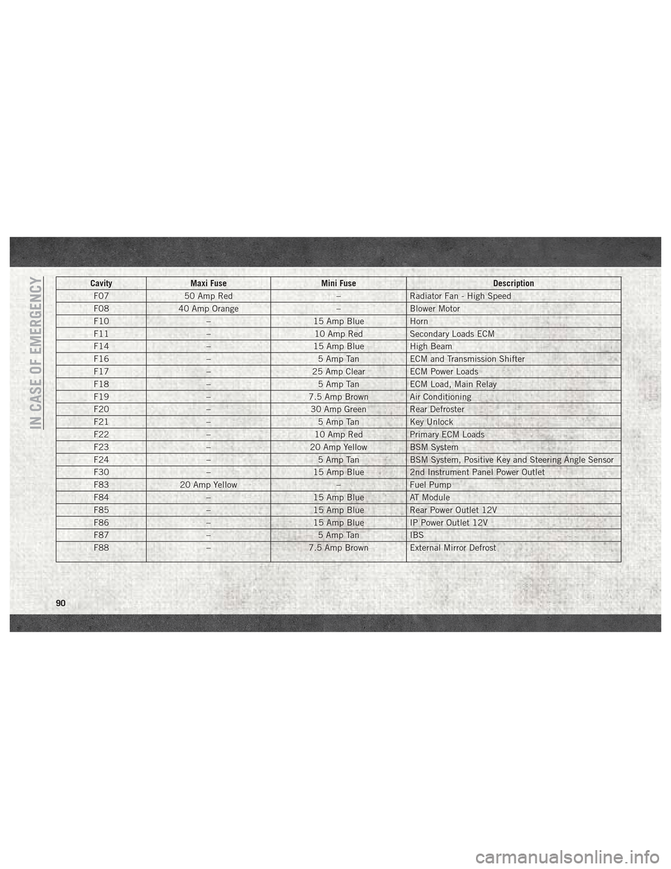
CavityMaxi Fuse Mini Fuse Description
F07 50 Amp Red –Radiator Fan - High Speed
F08 40 Amp Orange –Blower Motor
F10 –15 Amp BlueHorn
F11 –10 Amp RedSecondary Loads ECM
F14 –15 Amp BlueHigh Beam
F16 –5 Amp TanECM and Transmission Shifter
F17 –25 Amp ClearECM Power Loads
F18 –5 Amp TanECM Load, Main Relay
F19 –7.5 Amp Brown Air Conditioning
F20 –30 Amp Green Rear Defroster
F21 –5 Amp TanKey Unlock
F22 –10 Amp RedPrimary ECM Loads
F23 –20 Amp Yellow BSM System
F24 –5 Amp TanBSM System, Positive Key and Steering Angle Sensor
F30 –15 Amp Blue2nd Instrument Panel Power Outlet
F83 20 Amp Yellow –Fuel Pump
F84 –15 Amp BlueAT Module
F85 –15 Amp BlueRear Power Outlet 12V
F86 –15 Amp BlueIP Power Outlet 12V
F87 –5 Amp TanIBS
F88 –7.5 Amp Brown External Mirror Defrost
IN CASE OF EMERGENCY
90
Page 93 of 180
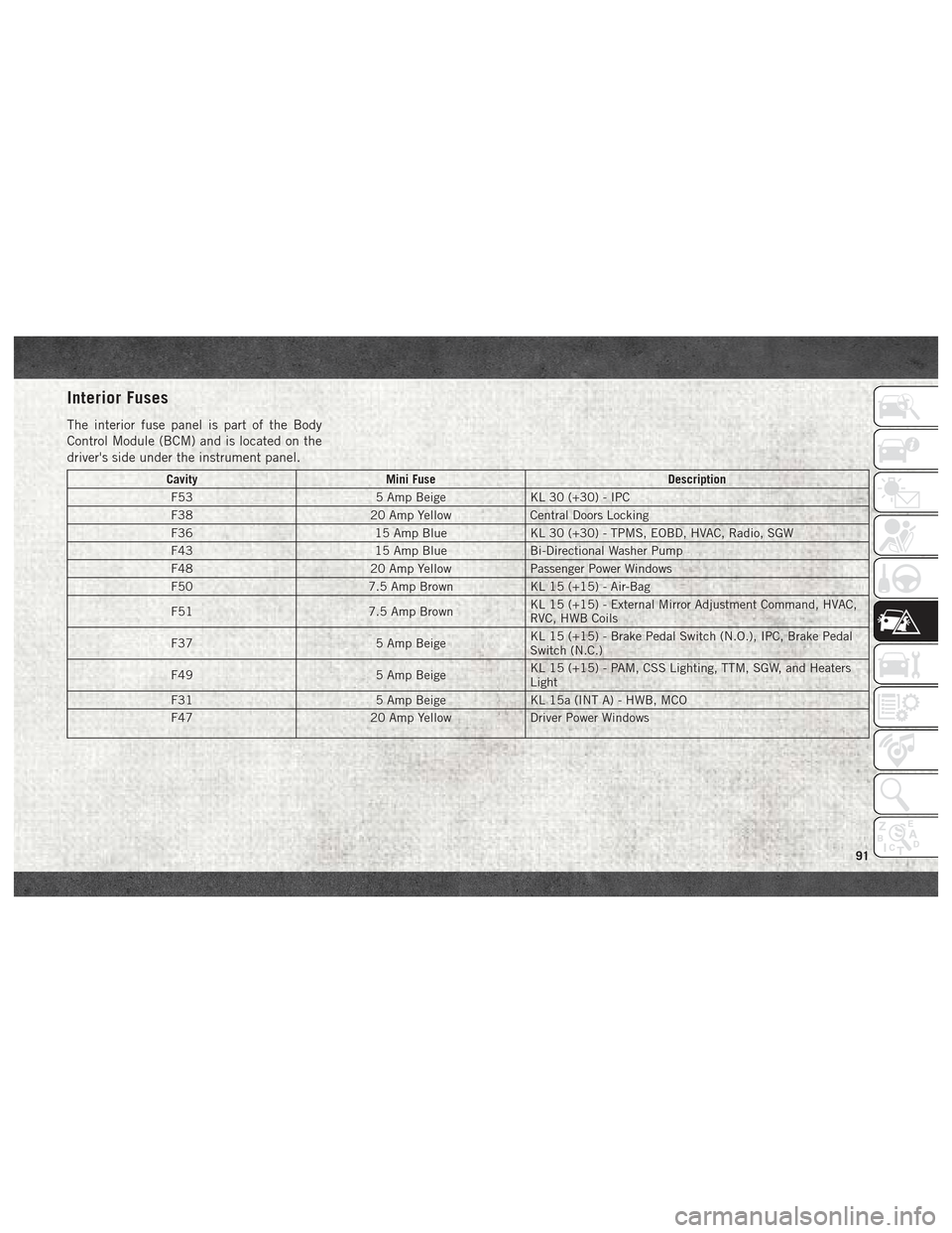
Interior Fuses
The interior fuse panel is part of the Body
Control Module (BCM) and is located on the
driver's side under the instrument panel.
CavityMini Fuse Description
F53 5 Amp BeigeKL 30 (+30) - IPC
F38 20 Amp YellowCentral Doors Locking
F36 15 Amp BlueKL 30 (+30) - TPMS, EOBD, HVAC, Radio, SGW
F43 15 Amp BlueBi-Directional Washer Pump
F48 20 Amp YellowPassenger Power Windows
F50 7.5 Amp BrownKL 15 (+15) - Air-Bag
F51 7.5 Amp BrownKL 15 (+15) - External Mirror Adjustment Command, HVAC,
RVC, HWB Coils
F37 5 Amp BeigeKL 15 (+15) - Brake Pedal Switch (N.O.), IPC, Brake Pedal
Switch (N.C.)
F49 5 Amp BeigeKL 15 (+15) - PAM, CSS Lighting, TTM, SGW, and Heaters
Light
F31 5 Amp BeigeKL 15a (INT A) - HWB, MCO
F47 20 Amp YellowDriver Power Windows
91
Page 96 of 180
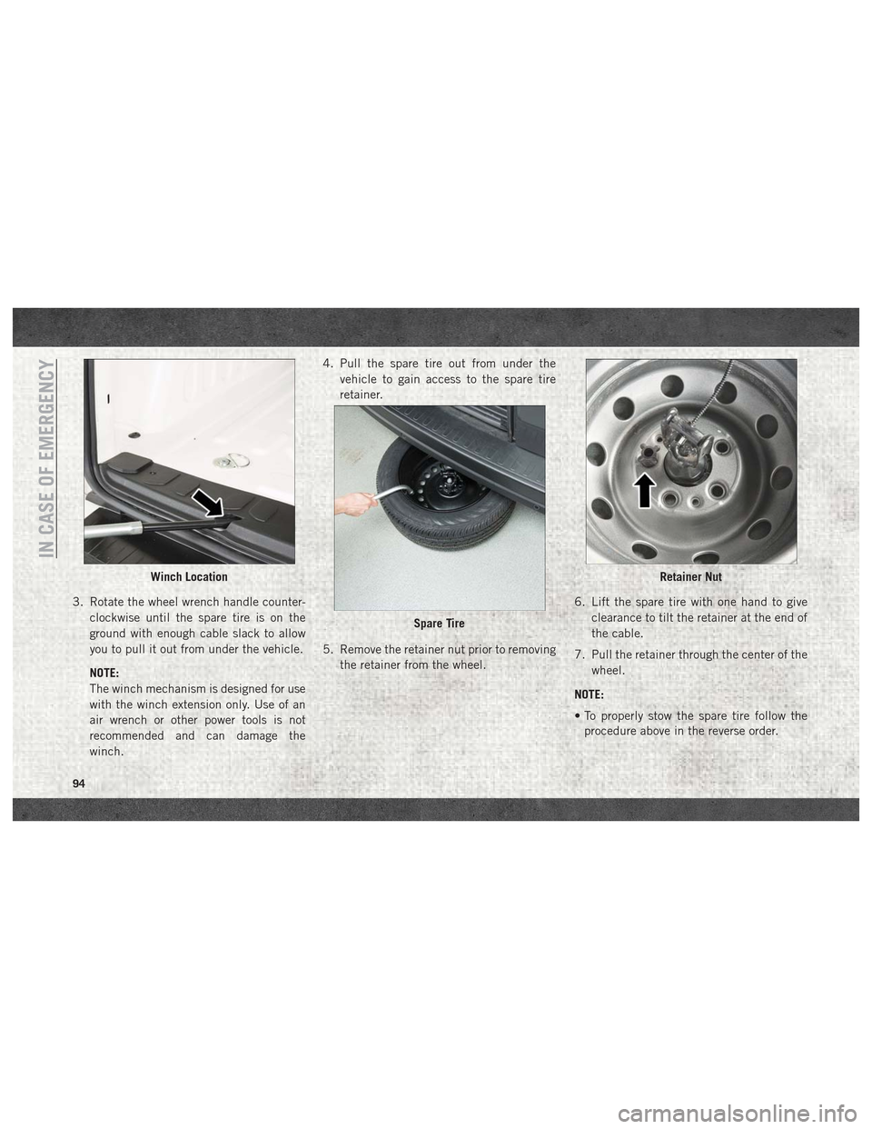
3. Rotate the wheel wrench handle counter-clockwise until the spare tire is on the
ground with enough cable slack to allow
you to pull it out from under the vehicle.
NOTE:
The winch mechanism is designed for use
with the winch extension only. Use of an
air wrench or other power tools is not
recommended and can damage the
winch. 4. Pull the spare tire out from under the
vehicle to gain access to the spare tire
retainer.
5. Remove the retainer nut prior to removing the retainer from the wheel. 6. Lift the spare tire with one hand to give
clearance to tilt the retainer at the end of
the cable.
7. Pull the retainer through the center of the wheel.
NOTE:
• To properly stow the spare tire follow the procedure above in the reverse order.
Winch Location
Spare Tire
Retainer Nut
IN CASE OF EMERGENCY
94
Page 100 of 180
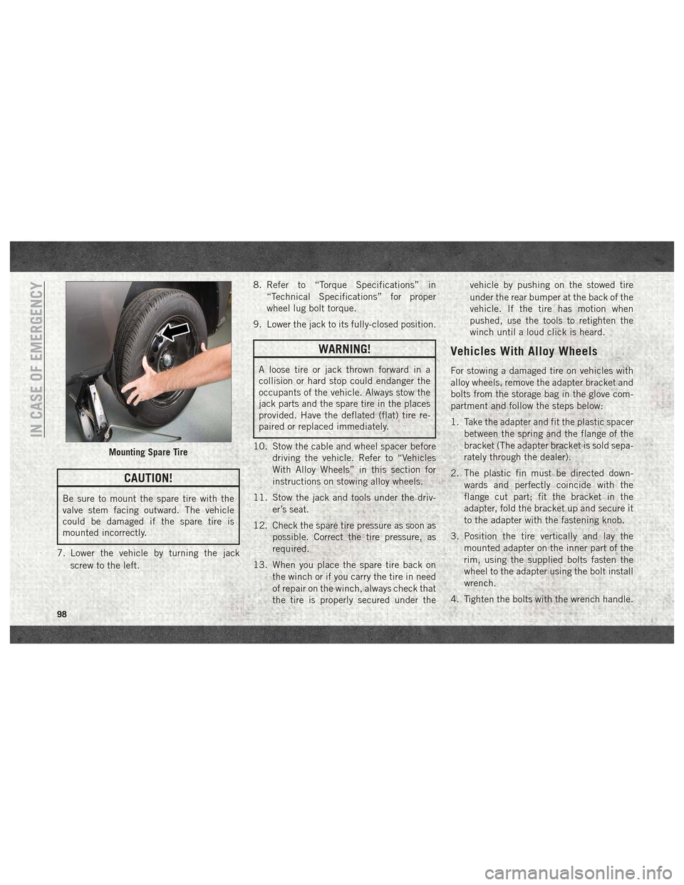
CAUTION!
Be sure to mount the spare tire with the
valve stem facing outward. The vehicle
could be damaged if the spare tire is
mounted incorrectly.
7. Lower the vehicle by turning the jack screw to the left. 8. Refer to “Torque Specifications” in
“Technical Specifications” for proper
wheel lug bolt torque.
9. Lower the jack to its fully-closed position.
WARNING!
A loose tire or jack thrown forward in a
collision or hard stop could endanger the
occupants of the vehicle. Always stow the
jack parts and the spare tire in the places
provided. Have the deflated (flat) tire re-
paired or replaced immediately.
10. Stow the cable and wheel spacer before driving the vehicle. Refer to “Vehicles
With Alloy Wheels” in this section for
instructions on stowing alloy wheels.
11. Stow the jack and tools under the driv- er’s seat.
12. Check the spare tire pressure as soon as possible. Correct the tire pressure, as
required.
13. When you place the spare tire back on the winch or if you carry the tire in need
of repair on the winch, always check that
the tire is properly secured under the vehicle by pushing on the stowed tire
under the rear bumper at the back of the
vehicle. If the tire has motion when
pushed, use the tools to retighten the
winch until a loud click is heard.
Vehicles With Alloy Wheels
For stowing a damaged tire on vehicles with
alloy wheels, remove the adapter bracket and
bolts from the storage bag in the glove com-
partment and follow the steps below:
1. Take the adapter and fit the plastic spacer
between the spring and the flange of the
bracket (The adapter bracket is sold sepa-
rately through the dealer).
2. The plastic fin must be directed down- wards and perfectly coincide with the
flange cut part; fit the bracket in the
adapter, fold the bracket up and secure it
to the adapter with the fastening knob.
3. Position the tire vertically and lay the mounted adapter on the inner part of the
rim, using the supplied bolts fasten the
wheel to the adapter using the bolt install
wrench.
4. Tighten the bolts with the wrench handle.
Mounting Spare Tire
IN CASE OF EMERGENCY
98
Page 102 of 180

TIRE SERVICE KIT — IF EQUIPPED
Small punctures up to ¼” (6 mm) in the tire
tread can be sealed with Tire Service Kit.
Foreign objects (e.g., screws or nails) should
not be removed from the tire. Tire Service Kit
can be used in outside temperatures down to
approximately -4°F (-20°C).
This kit will provide a temporary tire seal,
allowing you to drive your vehicle up to 100
miles (160 km) with a maximum speed of
65 mph (106 km/h).
Tire Service Kit Storage
The Tire Service Kit is located under the
passenger seat.
Tire Service Kit Usage
If a tire is punctured, you can make a first
emergency repair using the Tire Service Kit
located under the passenger seat.
Tire punctures of up to 1/4” (6 mm) can be
repaired; the kit can be used in all weather
conditions. Do not remove the foreign object
from the punctured tire, i.e., screw or nail.Remove the Tire Service Kit from the vehicle,
take it out from the bag and place it near the
punctured tire. Screw the clear flexible filling
tube to the tire valve.
WARNING!
• Do not attempt to seal a tire on the side
of the vehicle closest to traffic. Pull far
enough off the road to avoid the danger
of being hit when using the Tire Service
Kit.
• Do not use Tire Service Kit or drive the
vehicle under the following circum-
stances:• If the puncture in the tire tread is
approximately 1/4 inch (6 mm) or
larger.
• If the tire has any sidewall damage.
• If the tire has any damage from
driving with extremely low tire pres-
sure.
• If the tire has any damage from
driving on a flat tire.
• If the wheel has any damage.
• If you are unsure of the condition of
the tire or the wheel.
• Keep Tire Service Kit away from open
flames or heat source.
• A loose Tire Service Kit thrown forward
in a collision or hard stop could endan-
ger the occupants of the vehicle. Always
Tire Service Kit Components
1 — Sealant Bottle
2 — Pressure Gauge
3 — Power Plug (Located Behind Stor-
age Door)
4 — Power Button
5 — Sealant Hose (Clear)
IN CASE OF EMERGENCY
100
Page 103 of 180
WARNING!
stow the Tire Service Kit in the place
provided. Failure to follow these warn-
ings can result in injuries that are seri-
ous or fatal to you, your passengers, and
others around you.
• Take care not to allow the contents of
Tire Service Kit to come in contact with
hair, eyes, or clothing. Tire Service Kit
sealant is harmful if inhaled, swallowed,
or absorbed through the skin. It causes
skin, eye, and respiratory irritation.
Flush immediately with plenty of water if
there is any contact with eyes or skin.
Change clothing as soon as possible, if
there is any contact with clothing.
• Tire Service Kit Sealant solution con-
tains latex. In case of an allergic reac-
tion or rash, consult a physician imme-
diately. Keep Tire Service Kit out of
reach of children. If swallowed, rinse
mouth immediately with plenty of water
and drink plenty of water. Do not induce
vomiting! Consult a physician immedi-
ately. Insert the power plug into the vehicle power
outlet socket. Start the vehicle engine.
Push the Tire Service Kit power button to the
“I” position. The electric compressor will be
turned on, sealant and air will inflate the tire.
Minimum 26 psi (1.8 bar) of pressure should
be reached within 20 minutes. If the pressure
has not been reached, turn off and remove
the Tire Service Kit, drive the vehicle 30 feet
(10 meters) back and forth, to better distrib-
ute the sealant inside the tire.
Attach the clear flexible filling tube of the
compressor directly to the tire valve and re-
peat the inflation process.
When the correct pressure has been reached,
start driving the vehicle to uniformly distrib-
ute the sealant inside the tire. After 10 min-
utes, stop and check the tire pressure. If the
pressure is below 19 psi (1.3 bar), do not
drive the vehicle, as the tire is too damaged,
contact the nearest authorized dealer.
WARNING!
Tire Service Kit is not a permanent flat tire
repair. Have the tire inspected and re-
paired or replaced after using Tire Service
Kit. Do not exceed 65 mph (110 km/h)
until the tire is repaired or replaced. Fail-
ure to follow this warning can result in
injuries that are serious or fatal to you,
your passengers, and others around you.
Have the tire checked as soon as possible
at an authorized dealer.
If the pressure is at 19 psi (1.3 bar) or above
repeat the inflation process to reach the cor-
rect tire pressure and continue driving.
Peel off the warning label from the bottle and
place it on the dashboard as a reminder to the
driver that a tire has been treated with Tire
Service Kit.
WARNING!
The metal end fitting from Power Plug may
get hot after use, so it should be handled
carefully.
101