Ram ProMaster City 2018 Manual Online
Manufacturer: RAM, Model Year: 2018, Model line: ProMaster City, Model: Ram ProMaster City 2018Pages: 180, PDF Size: 7.52 MB
Page 81 of 180
STARTING AND OPERATING
ENGINE BREAK-IN
RECOMMENDATIONS — GASOLINE
ENGINE.....................80
SPEED CONTROL ...............80
To Activate...................81
To Set A Desired Speed ...........81
To Vary The Speed Setting ..........81
To Accelerate For Passing ..........82To Resume Speed
...............82
To Deactivate .................82
PARKSENSE REAR PARK ASSIST .....82
PARKVIEW REAR BACK UP CAMERA . . .82
REFUELING THE VEHICLE ..........84
Materials Added To Fuel ..........85
TRAILER TOWING..............85
Trailer Towing Weights (Maximum Trailer
Weight Ratings)................85
RECREATIONAL TOWING
(BEHIND MOTORHOME, ETC.) .......85
Towing This Vehicle Behind Another
Vehicle.....................85
Recreational Towing — Automatic
Transmission ..................86
STARTING AND OPERATING
79
Page 82 of 180
ENGINE BREAK-IN
RECOMMENDATIONS — GASOLINE
ENGINE
A long break-in period is not required for the
engine and drivetrain (transmission and axle)
in your vehicle.
Drive moderately during the first 300 miles
(500 km). After the initial 60 miles
(100 km), speeds up to 50 or 55 mph (80 or
90 km/h) are desirable.
While cruising, brief full-throttle acceleration
within the limits of local traffic laws contrib-
utes to a good break-in. Wide-open throttle
acceleration in low gear can be detrimental
and should be avoided.
The engine oil installed in the engine at the
factory is a high-quality energy conserving
type lubricant. Oil changes should be consis-
tent with anticipated climate conditions un-
der which vehicle operations will occur. For
the recommended viscosity and quality
grades, refer to “Fluids And Lubricants” in
“Technical Specifications”.
CAUTION!
Never use Non-Detergent Oil or Straight
Mineral Oil in the engine or damage may
result.
NOTE:
A new engine may consume some oil during
its first few thousand miles (kilometers) of
operation. This should be considered a nor-
mal part of the break-in and not interpreted
as a problem. Please check your oil level with
the engine oil indicator often during the
break in period. Add oil as required.
SPEED CONTROL
When engaged, the Speed Control takes over
accelerator operations at speeds greater than
25 mph (40 km/h).
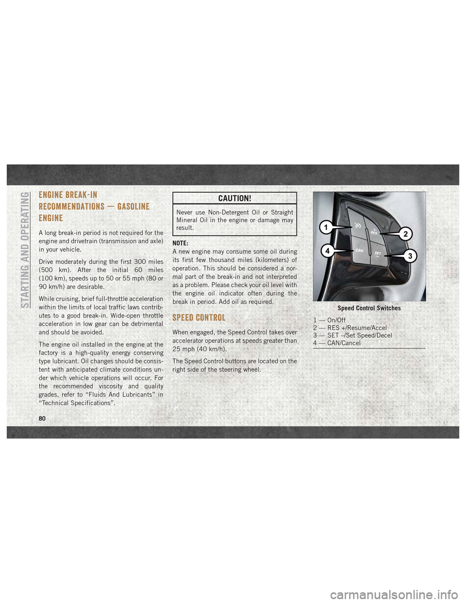
The Speed Control buttons are located on the
right side of the steering wheel.
Speed Control Switches
1 — On/Off
2 — RES +/Resume/Accel
3 — SET –/Set Speed/Decel
4 — CAN/Cancel
STARTING AND OPERATING
80
Page 83 of 180
NOTE:
In order to ensure proper operation, the
Speed Control System has been designed to
shut down if multiple Speed Control func-
tions are operated at the same time. If this
occurs, the Speed Control System can be
reactivated by pushing the on/off button and
resetting the desired vehicle set speed.
To Activate
Push the on/off button to activate the Speed
Control. The cruise indicator light in the in-
strument cluster display will illuminate. To
turn the system off, push the on/off button a
second time. The cruise indicator light will
turn off. The system should be turned off
when not in use.
WARNING!
Leaving the Speed Control system on when
not in use is dangerous. You could acci-
dentally set the system or cause it to go
faster than you want. You could lose con-
trol and have an accident. Always leave the
system off when you are not using it.
To Set A Desired Speed
Turn the Speed Control on. When the vehicle
has reached the desired speed greater than
25 mph (40 km/h), push the SET (-) button
and release. Release the accelerator and the
vehicle will operate at the selected speed.
NOTE:
The vehicle should be traveling at a steady
speed and on level ground before pushing the
SET (-) button.
To Vary The Speed Setting
To Increase Speed
When the Speed Control is set, you can in-
crease speed by pushing the RES (+) button.
The speed increment is dependant on the
chosen speed unit of U.S. (mph) or Metric
(km/h):
U.S. Speed (mph)
• Pushing the RES (+) button once will resultin a 1 mph increase in set speed. Each
subsequent tap of the button results in an
increase of 1 mph. • If the button is continually pushed, the set
speed will continue to increase until the
button is released, then the new set speed
will be established.
Metric Speed (km/h)
• Pushing the RES (+) button once will result in a 1 km/h increase in set speed. Each
subsequent tap of the button results in an
increase of 1 km/h.
• If the button is continually pushed, the set speed will continue to increase until the
button is released, then the new set speed
will be established.
To Decrease Speed
When the Speed Control is set, you can de-
crease speed by pushing the SET (-) button.
The speed decrement is dependant on the
chosen speed unit of U.S. (mph) or Metric
(km/h):
U.S. Speed (mph)
• Pushing the SET (-) button once will result in a 1 mph decrease in set speed. Each
subsequent tap of the button results in a
decrease of 1 mph.
81
Page 84 of 180
• If the button is continually pushed, the setspeed will continue to decrease until the
button is released, then the new set speed
will be established.
Metric Speed (km/h)
• Pushing the SET (-) button once will result in a 1 km/h decrease in set speed. Each
subsequent tap of the button results in a
decrease of 1 km/h.
• If the button is continually pushed, the set speed will continue to decrease until the
button is released, then the new set speed
will be established.
To Accelerate For Passing
Press the accelerator as you would normally.
When the pedal is released, the vehicle will
return to the set speed.
Using Speed Control On Hills
The transmission may downshift on hills to
maintain the vehicle set speed.
NOTE:
The Speed Control system maintains speed
up and down hills. A slight speed change on
moderate hills is normal. On steep hills, a greater speed loss or gain
may occur so it may be preferable to drive
without Speed Control.
WARNING!
Speed Control can be dangerous where the
system cannot maintain a constant speed.
Your vehicle could go too fast for the con-
ditions, and you could lose control and
have an accident. Do not use Speed Con-
trol in heavy traffic or on roads that are
winding, icy, snow-covered or slippery.
To Resume Speed
To resume a previously set speed, push the
RES (+) button and release. Resume can be
used at any speed above 20 mph (32 km/h)
up to the maximum speed of 100 mph
(160 km/h).
To Deactivate
A soft tap on the brake pedal, pushing the
CANC button, or normal brake pressure while
slowing the vehicle will deactivate the Speed
Control without erasing the set speed from
memory.
Pushing the on/off button or turning the igni-
tion switch OFF erases the set speed from
memory.
PARKSENSE REAR PARK ASSIST
If an object is detected behind the rear bum-
per while the vehicle is in REVERSE, a chime
sounds. The chime rate changes depending
on the distance of the object, getting faster
as the object gets closer to the bumper. The
chime sounds off continuously when the dis-
tance between the vehicle and the obstacle is
less than 12 inches (30 cm).
PARKVIEW REAR BACK UP CAMERA
Your vehicle is equipped with the ParkView
Rear Back Up Camera that allows you to see
an on-screen image of the rear surroundings
of your vehicle whenever the gear selector is
put into REVERSE. The image will be dis-
played on the touchscreen display along with
a caution note to “check entire surround-
ings” across the top of the screen. After five
seconds this note will disappear. The
ParkView camera is located on the rear of the
vehicle above the rear license plate.
STARTING AND OPERATING
82
Page 85 of 180
The Rear Back Up Camera can also be acti-
vated when the vehicle is not in REVERSE
through the Uconnect System. Refer to
“Uconnect 3/3 NAV With 5-inch Display”
supplement for further information.
NOTE:
If one of the rear cargo doors is not com-
pletely closed, the Back Up Camera cannot
provide an accurate image of the area behind
the vehicle. A dedicated message will appear
on the Uconnect display indicating the cam-
era is not in the correct position.The Camera Delay setting can be set to on/off
in the rear camera settings menu. When the
vehicle is shifted out of REVERSE and the
Camera Delay is turned off, the rear camera
mode is exited and the navigation or audio
screen appears on display again.
When the transmission is shifted out of RE-
VERSE, and Camera Delay is activated in the
menu screen, the camera image will continue
to be displayed for up to 10 seconds, unless
the speed of the vehicle is greater than 8 mph
(13 km/h), the transmission is in PARK, or
the ignition key is in the OFF position.The display of the camera image can be
enabled or disabled through the rear camera
setting menu item (Camera on/off).
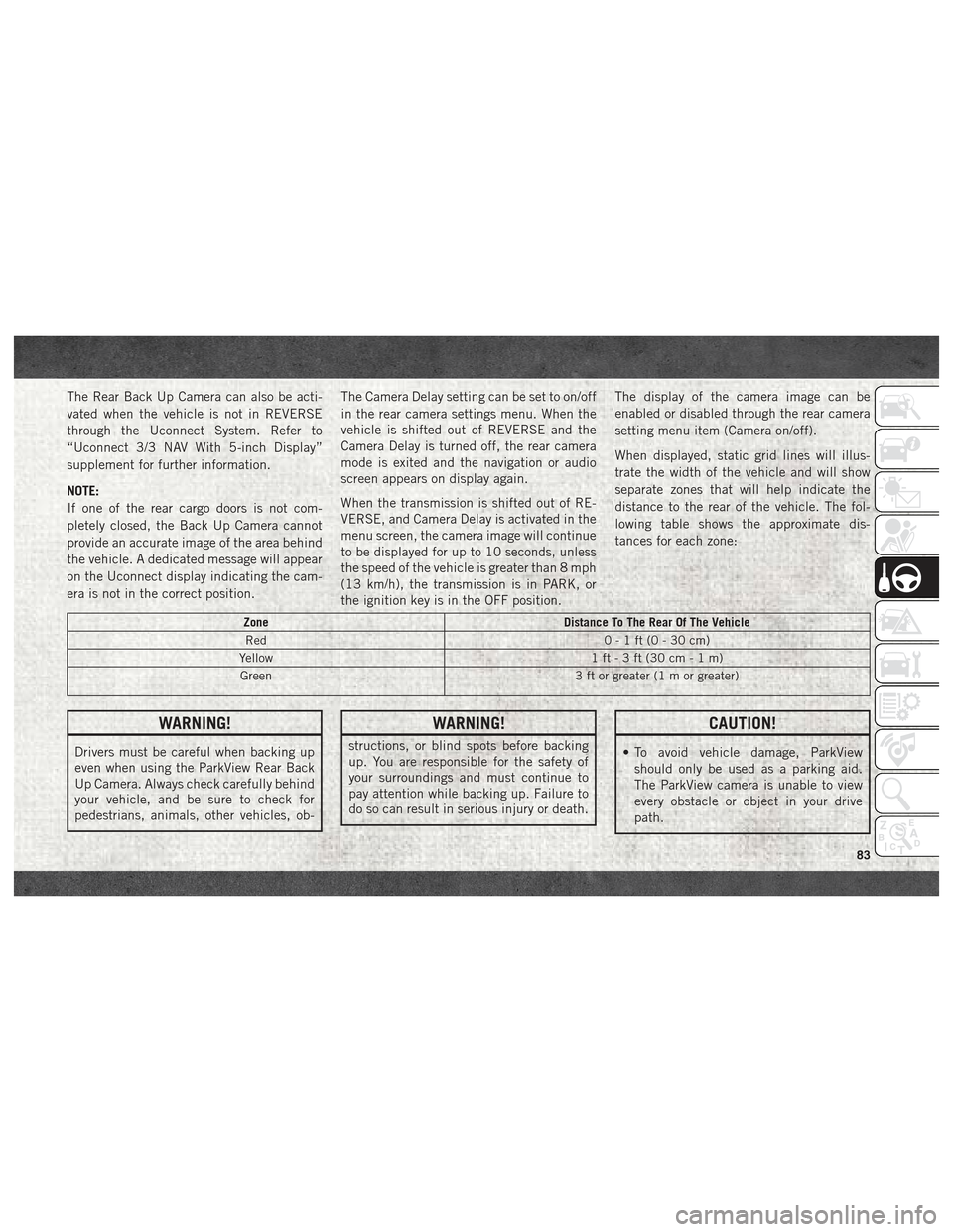
When displayed, static grid lines will illus-
trate the width of the vehicle and will show
separate zones that will help indicate the
distance to the rear of the vehicle. The fol-
lowing table shows the approximate dis-
tances for each zone:
Zone
Distance To The Rear Of The Vehicle
Red 0-1ft(0-30cm)
Yellow 1 ft - 3 ft (30 cm - 1 m)
Green 3 ft or greater (1 m or greater)
WARNING!
Drivers must be careful when backing up
even when using the ParkView Rear Back
Up Camera. Always check carefully behind
your vehicle, and be sure to check for
pedestrians, animals, other vehicles, ob-
WARNING!
structions, or blind spots before backing
up. You are responsible for the safety of
your surroundings and must continue to
pay attention while backing up. Failure to
do so can result in serious injury or death.
CAUTION!
• To avoid vehicle damage, ParkView
should only be used as a parking aid.
The ParkView camera is unable to view
every obstacle or object in your drive
path.
83
Page 86 of 180
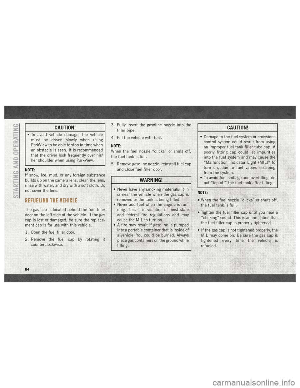
CAUTION!
• To avoid vehicle damage, the vehiclemust be driven slowly when using
ParkView to be able to stop in time when
an obstacle is seen. It is recommended
that the driver look frequently over his/
her shoulder when using ParkView.
NOTE:
If snow, ice, mud, or any foreign substance
builds up on the camera lens, clean the lens,
rinse with water, and dry with a soft cloth. Do
not cover the lens.
REFUELING THE VEHICLE
The gas cap is located behind the fuel filler
door on the left side of the vehicle. If the gas
cap is lost or damaged, be sure the replace-
ment cap is for use with this vehicle.
1. Open the fuel filler door.
2. Remove the fuel cap by rotating it counterclockwise. 3. Fully insert the gasoline nozzle into the
filler pipe.
4. Fill the vehicle with fuel.
NOTE:
When the fuel nozzle “clicks” or shuts off,
the fuel tank is full.
5. Remove gasoline nozzle, reinstall fuel cap and close fuel filler door.
WARNING!
• Never have any smoking materials lit inor near the vehicle when the gas cap is
removed or the tank is being filled.
• Never add fuel when the engine is run-
ning. This is in violation of most state
and federal fire regulations and may
cause the MIL to turn on.
• A fire may result if gasoline is pumped
into a portable container that is inside of
a vehicle. You could be burned. Always
place gas containers on the ground while
filling.
CAUTION!
• Damage to the fuel system or emissionscontrol system could result from using
an improper fuel tank filler tube cap. A
poorly fitting cap could let impurities
into the fuel system and may cause the
“Malfunction Indicator Light (MIL)” to
turn on, due to fuel vapors escaping
from the system.
• To avoid fuel spillage and overfilling, do
not “top off” the fuel tank after filling.
NOTE:
• When the fuel nozzle “clicks” or shuts off, the fuel tank is full.
• Tighten the fuel filler cap until you hear a “clicking” sound. This is an indication that
the fuel filler cap is properly tightened.
• If the gas cap is not tightened properly, the MIL may come on. Be sure the gas cap is
tightened every time the vehicle is
refueled.
STARTING AND OPERATING
84
Page 87 of 180
Materials Added To Fuel
Designated TOP TIER
Detergent Gasoline
contains a higher level
of detergents to further
aide in minimizing en-
gine and fuel system
deposits. When avail-
able, the usage of Top
Tier Detergent gasoline is recommended.
Visit www.toptiergas.com for a list of TOP
TIER Detergent Gasoline Retailers. Indiscriminate use of fuel system cleaning
agents should be avoided. Many of these
materials intended for gum and varnish re-
moval may contain active solvents or similar
ingredients. These can harm fuel system gas-
ket and diaphragm materials.
TRAILER TOWING
Trailer Towing Weights (Maximum
Trailer Weight Ratings)
NOTE:
For trailer towing information (maximum
trailer weight ratings) refer to the following
website addresses:
•
ramtrucks.com/en/towing_guide/
• ramtruck.ca (Canada)
• rambodybuilder.com
RECREATIONAL TOWING (BEHIND MOTORHOME, ETC.)
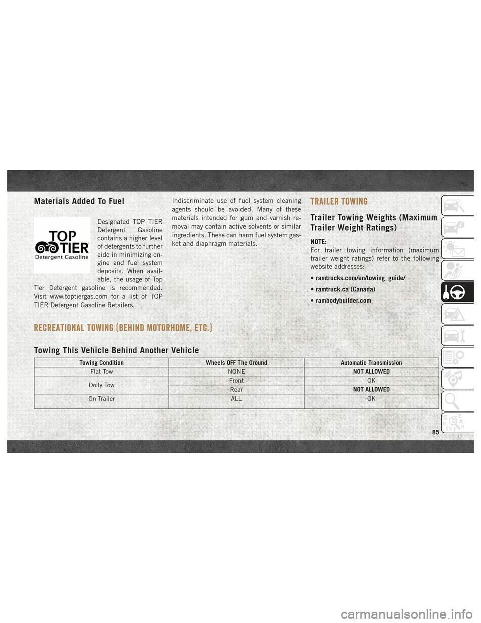
Towing This Vehicle Behind Another Vehicle
Towing Condition Wheels OFF The Ground Automatic Transmission
Flat Tow NONENOT ALLOWED
Dolly Tow Front
OK
Rear NOT ALLOWED
On Trailer ALLOK
85
Page 88 of 180
NOTE:
When towing your vehicle, always follow ap-
plicable state and provincial laws. Contact
state and provincial Highway Safety offices
for additional details.
Recreational Towing — Automatic
Transmission
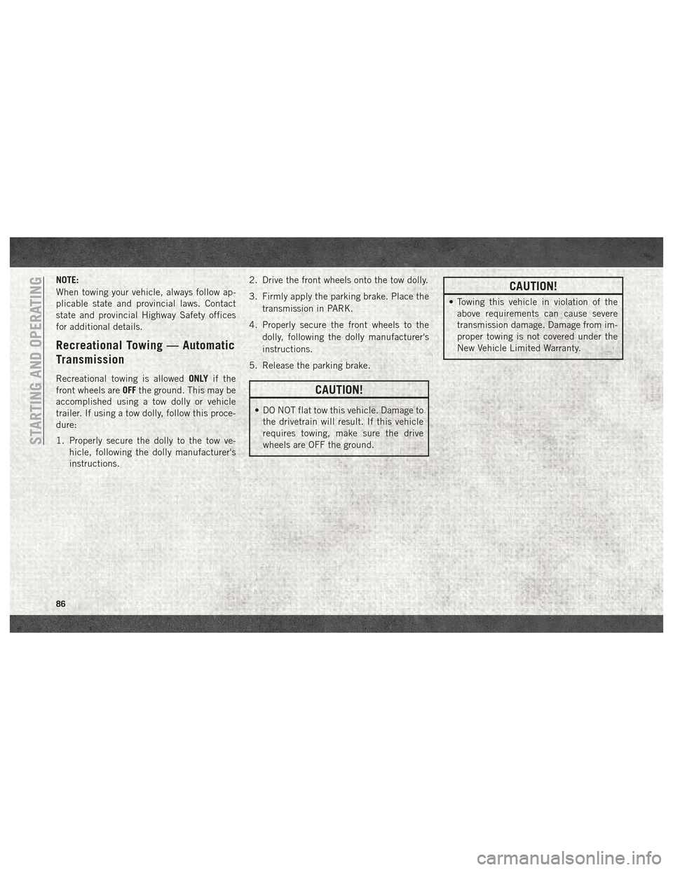
Recreational towing is allowedONLYif the
front wheels are OFFthe ground. This may be
accomplished using a tow dolly or vehicle
trailer. If using a tow dolly, follow this proce-
dure:
1. Properly secure the dolly to the tow ve- hicle, following the dolly manufacturer's
instructions. 2. Drive the front wheels onto the tow dolly.
3. Firmly apply the parking brake. Place the
transmission in PARK.
4. Properly secure the front wheels to the dolly, following the dolly manufacturer's
instructions.
5. Release the parking brake.
CAUTION!
• DO NOT flat tow this vehicle. Damage to the drivetrain will result. If this vehicle
requires towing, make sure the drive
wheels are OFF the ground.
CAUTION!
• Towing this vehicle in violation of theabove requirements can cause severe
transmission damage. Damage from im-
proper towing is not covered under the
New Vehicle Limited Warranty.
STARTING AND OPERATING
86
Page 89 of 180
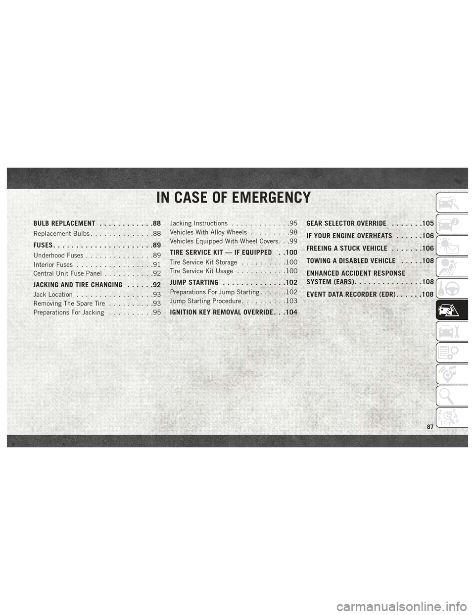
IN CASE OF EMERGENCY
BULB REPLACEMENT............88
Replacement Bulbs..............88
FUSES......................89
Underhood Fuses ...............89
Interior Fuses .................91
Central Unit Fuse Panel ...........92
JACKING AND TIRE CHANGING ......92
Jack Location.................93
Removing The Spare Tire ..........93
Preparations For Jacking ..........95Jacking Instructions
.............95
Vehicles With Alloy Wheels .........98
Vehicles Equipped With Wheel Covers. . .99
TIRE SERVICE KIT — IF EQUIPPED . .100
Tire Service Kit Storage ..........100
Tire Service Kit Usage ...........100
JUMP STARTING..............102
Preparations For Jump Starting ......102
Jump Starting Procedure ..........103
IGNITION KEY REMOVAL OVERRIDE . . .104 GEAR SELECTOR OVERRIDE
.......105
IF YOUR ENGINE OVERHEATS ......106
FREEING A STUCK VEHICLE .......106
TOWING A DISABLED VEHICLE .....108
ENHANCED ACCIDENT RESPONSE
SYSTEM (EARS) ...............108
EVENT DATA RECORDER (EDR) ......108
IN CASE OF EMERGENCY
87
Page 90 of 180
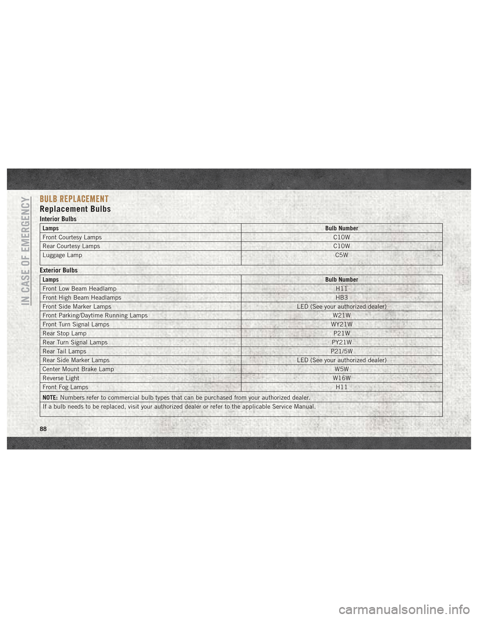
BULB REPLACEMENT
Replacement Bulbs
Interior Bulbs
LampsBulb Number
Front Courtesy Lamps C10W
Rear Courtesy Lamps C10W
Luggage Lamp C5W
Exterior Bulbs
LampsBulb Number
Front Low Beam Headlamp H11
Front High Beam Headlamps HB3
Front Side Marker Lamps LED (See your authorized dealer)
Front Parking/Daytime Running Lamps W21W
Front Turn Signal Lamps WY21W
Rear Stop Lamp P21W
Rear Turn Signal Lamps PY21W
Rear Tail Lamps P21/5W
Rear Side Marker Lamps LED (See your authorized dealer)
Center Mount Brake Lamp W5W
Reverse Light W16W
Front Fog Lamps H11
NOTE: Numbers refer to commercial bulb types that can be purchased from your authorized dealer.
If a bulb needs to be replaced, visit your authorized dealer or refer to the applicable Service Manual.
IN CASE OF EMERGENCY
88