Ram ProMaster City 2018 Owners Manual
Manufacturer: RAM, Model Year: 2018, Model line: ProMaster City, Model: Ram ProMaster City 2018Pages: 180, PDF Size: 7.52 MB
Page 91 of 180

FUSES
WARNING!
• When replacing a blown fuse, always usean appropriate replacement fuse with
the same amp rating as the original fuse.
Never replace a fuse with another fuse of
higher amp rating. Never replace a
blown fuse with metal wires or any other
material. Do not place a fuse inside a
circuit breaker cavity or vice versa. Fail-
ure to use proper fuses may result in
WARNING!
serious personal injury, fire and/or prop-
erty damage.
• Before replacing a fuse, make sure that
the ignition is off and that all the other
services are switched off and/or disen-
gaged.
• If the replaced fuse blows again, contact
an authorized dealer.
• If a general protection fuse for safety
systems (air bag system, braking sys-
tem), power unit systems (engine sys-
tem, transmission system) or steering
WARNING!
system blows, contact an authorized
dealer.
Underhood Fuses
The Front Distribution Unit is located on the
right side of the engine compartment, next to
the battery. To access the fuses, remove fas-
teners and remove the cover.
The ID number of the electrical component
corresponding to each fuse can be found on
the back of the cover.
Cavity Maxi Fuse Mini Fuse Description
F01 60 Amp Blue –Body Controller
F02 40 Amp Orange –Rear Power Windows, Fog Lamps, Front Heated Seats
(If Equipped)
F02 30 Amp Green –Rear Power Windows, Front Heated Seats (If
Equipped)
F02 30 Amp Green –Fog Lamps, Front Heated Seats (If Equipped)
F02 20 Amp Yellow –Front Heated Seats
F03 20 Amp Yellow –Ignition Switch
F04 40 Amp Orange –BSM System Module
F06 20 Amp Yellow –Radiator Fan - Low Speed
89
Page 92 of 180
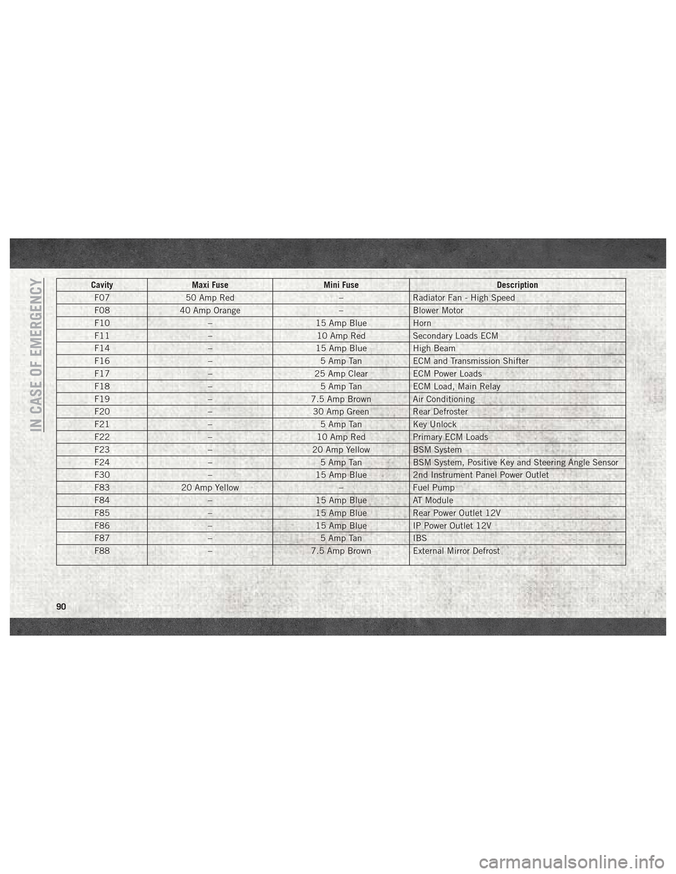
CavityMaxi Fuse Mini Fuse Description
F07 50 Amp Red –Radiator Fan - High Speed
F08 40 Amp Orange –Blower Motor
F10 –15 Amp BlueHorn
F11 –10 Amp RedSecondary Loads ECM
F14 –15 Amp BlueHigh Beam
F16 –5 Amp TanECM and Transmission Shifter
F17 –25 Amp ClearECM Power Loads
F18 –5 Amp TanECM Load, Main Relay
F19 –7.5 Amp Brown Air Conditioning
F20 –30 Amp Green Rear Defroster
F21 –5 Amp TanKey Unlock
F22 –10 Amp RedPrimary ECM Loads
F23 –20 Amp Yellow BSM System
F24 –5 Amp TanBSM System, Positive Key and Steering Angle Sensor
F30 –15 Amp Blue2nd Instrument Panel Power Outlet
F83 20 Amp Yellow –Fuel Pump
F84 –15 Amp BlueAT Module
F85 –15 Amp BlueRear Power Outlet 12V
F86 –15 Amp BlueIP Power Outlet 12V
F87 –5 Amp TanIBS
F88 –7.5 Amp Brown External Mirror Defrost
IN CASE OF EMERGENCY
90
Page 93 of 180
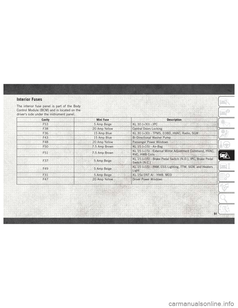
Interior Fuses
The interior fuse panel is part of the Body
Control Module (BCM) and is located on the
driver's side under the instrument panel.
CavityMini Fuse Description
F53 5 Amp BeigeKL 30 (+30) - IPC
F38 20 Amp YellowCentral Doors Locking
F36 15 Amp BlueKL 30 (+30) - TPMS, EOBD, HVAC, Radio, SGW
F43 15 Amp BlueBi-Directional Washer Pump
F48 20 Amp YellowPassenger Power Windows
F50 7.5 Amp BrownKL 15 (+15) - Air-Bag
F51 7.5 Amp BrownKL 15 (+15) - External Mirror Adjustment Command, HVAC,
RVC, HWB Coils
F37 5 Amp BeigeKL 15 (+15) - Brake Pedal Switch (N.O.), IPC, Brake Pedal
Switch (N.C.)
F49 5 Amp BeigeKL 15 (+15) - PAM, CSS Lighting, TTM, SGW, and Heaters
Light
F31 5 Amp BeigeKL 15a (INT A) - HWB, MCO
F47 20 Amp YellowDriver Power Windows
91
Page 94 of 180
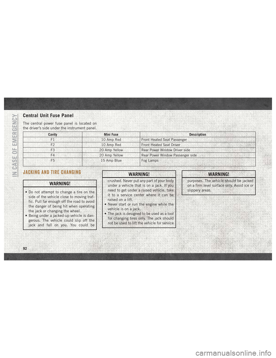
Central Unit Fuse Panel
The central power fuse panel is located on
the driver’s side under the instrument panel.
CavityMini Fuse Description
F1 10 Amp RedFront Heated Seat Passenger
F2 10 Amp RedFront Heated Seat Driver
F3 20 Amp YellowRear Power Window Driver side
F4 20 Amp YellowRear Power Window Passenger side
F5 15 Amp BlueFog Lamps
JACKING AND TIRE CHANGING
WARNING!
• Do not attempt to change a tire on the
side of the vehicle close to moving traf-
fic. Pull far enough off the road to avoid
the danger of being hit when operating
the jack or changing the wheel.
• Being under a jacked-up vehicle is dan-
gerous. The vehicle could slip off the
jack and fall on you. You could be
WARNING!
crushed. Never put any part of your body
under a vehicle that is on a jack. If you
need to get under a raised vehicle, take
it to a service center where it can be
raised on a lift.
• Never start or run the engine while the
vehicle is on a jack.
• The jack is designed to be used as a tool
for changing tires only. The jack should
not be used to lift the vehicle for service
WARNING!
purposes. The vehicle should be jacked
on a firm level surface only. Avoid ice or
slippery areas.
IN CASE OF EMERGENCY
92
Page 95 of 180

Jack Location
The jack and tools are stowed under the
driver’s front seat.
Removing The Spare Tire
1. Remove the spare tire before attemptingto jack up the vehicle. Attach the wrench
handle to the winch extension. 2. To access the winch mechanism open the
rear doors of the vehicle to expose the winch mechanism access cover. Remove
the access cover and install the winch
extension into the winch mechanism.
Jack/Tools Location
Jack Tools
1 — Wrench Handle
2 — Winch Extension
3 — Emergency Screwdriver
4 — Bolt Install Wrench
5 — Wheel Chock
6 — Jack
Jack Tools
1 — Wrench Handle
2 — Winch Extension
93
Page 96 of 180
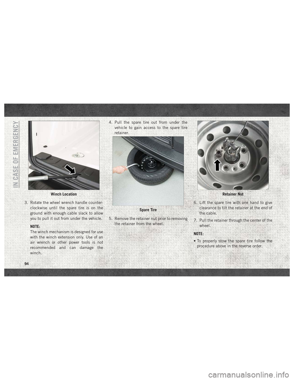
3. Rotate the wheel wrench handle counter-clockwise until the spare tire is on the
ground with enough cable slack to allow
you to pull it out from under the vehicle.
NOTE:
The winch mechanism is designed for use
with the winch extension only. Use of an
air wrench or other power tools is not
recommended and can damage the
winch. 4. Pull the spare tire out from under the
vehicle to gain access to the spare tire
retainer.
5. Remove the retainer nut prior to removing the retainer from the wheel. 6. Lift the spare tire with one hand to give
clearance to tilt the retainer at the end of
the cable.
7. Pull the retainer through the center of the wheel.
NOTE:
• To properly stow the spare tire follow the procedure above in the reverse order.
Winch Location
Spare Tire
Retainer Nut
IN CASE OF EMERGENCY
94
Page 97 of 180
• When winching the tire back into place, thewinch will make three audible noises once
secure. Reach underneath and shake tire
by hand to confirm that it is secure. The tire
should not move. If tire is still loose and/or
three audible noises are not heard, place
and secure damaged wheel into the vehicle
and seek dealer assistance for the winch
mechanism.
Preparations For Jacking
1. Park the vehicle on a firm level surface as
far from the edge of the roadway as pos-
sible. Avoid icy or slippery areas.
WARNING!
Do not attempt to change a tire on the side
of the vehicle close to moving traffic, pull
far enough off the road to avoid being hit
when operating the jack or changing the
wheel.
2. Turn on the Hazard Warning flasher.
3. Apply the parking brake. 4. Place the gear selector into PARK.
5. Turn the ignition off to the LOCK position.
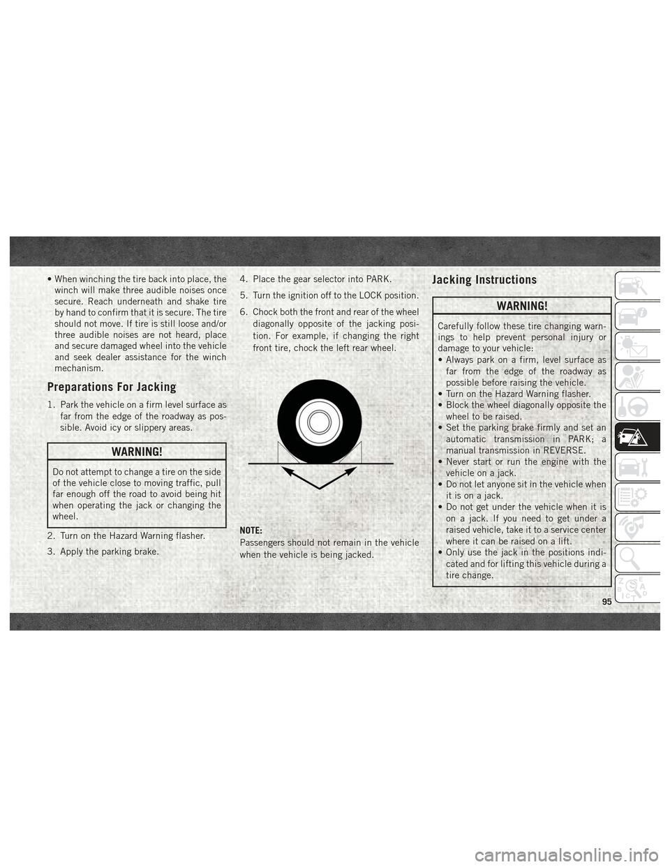
6. Chock both the front and rear of the wheel
diagonally opposite of the jacking posi-
tion. For example, if changing the right
front tire, chock the left rear wheel.
NOTE:
Passengers should not remain in the vehicle
when the vehicle is being jacked.
Jacking Instructions
WARNING!
Carefully follow these tire changing warn-
ings to help prevent personal injury or
damage to your vehicle:
• Always park on a firm, level surface as far from the edge of the roadway as
possible before raising the vehicle.
• Turn on the Hazard Warning flasher.
• Block the wheel diagonally opposite the
wheel to be raised.
• Set the parking brake firmly and set an
automatic transmission in PARK; a
manual transmission in REVERSE.
• Never start or run the engine with the
vehicle on a jack.
• Do not let anyone sit in the vehicle when
it is on a jack.
• Do not get under the vehicle when it is
on a jack. If you need to get under a
raised vehicle, take it to a service center
where it can be raised on a lift.
• Only use the jack in the positions indi-
cated and for lifting this vehicle during a
tire change.
95
Page 98 of 180
WARNING!
• If working on or near a roadway, beextremely careful of motor traffic.
• To assure that spare tires, flat or in-
flated, are securely stowed, spares must
be stowed with the valve stem facing the
ground.
• The stowed spare tire should always be
checked for security by pushing on it
with your hand , at the location under
the rear bumper, behind the vehicle. The
spare tire should not move when fully
secured by the winch under the vehicle.
CAUTION!
Do not attempt to raise the vehicle by
jacking on locations other than those indi-
cated in the Jacking Instructions for this
vehicle.
1. Loosen (but do not remove) the wheel lug bolts with the wrench handle by turning
them to the left one turn while the wheel
is still on the ground. 2. There are two jack engagement locations
on each side of the vehicle body.
NOTE:
Place the jack underneath the jack engage-
ment location that is closest to the flat tire.
WARNING!
Being under a jacked-up vehicle is danger-
ous. The vehicle could slip off the jack and
fall on you. You could be crushed. Never
get any part of your body under a vehicle
that is on a jack. If you need to get under a
raised vehicle, take it to a service center
where it can be raised on a lift.
CAUTION!
Do not attempt to raise the vehicle by
jacking on locations other than those indi-
cated in the Jacking Instructions for this
vehicle.
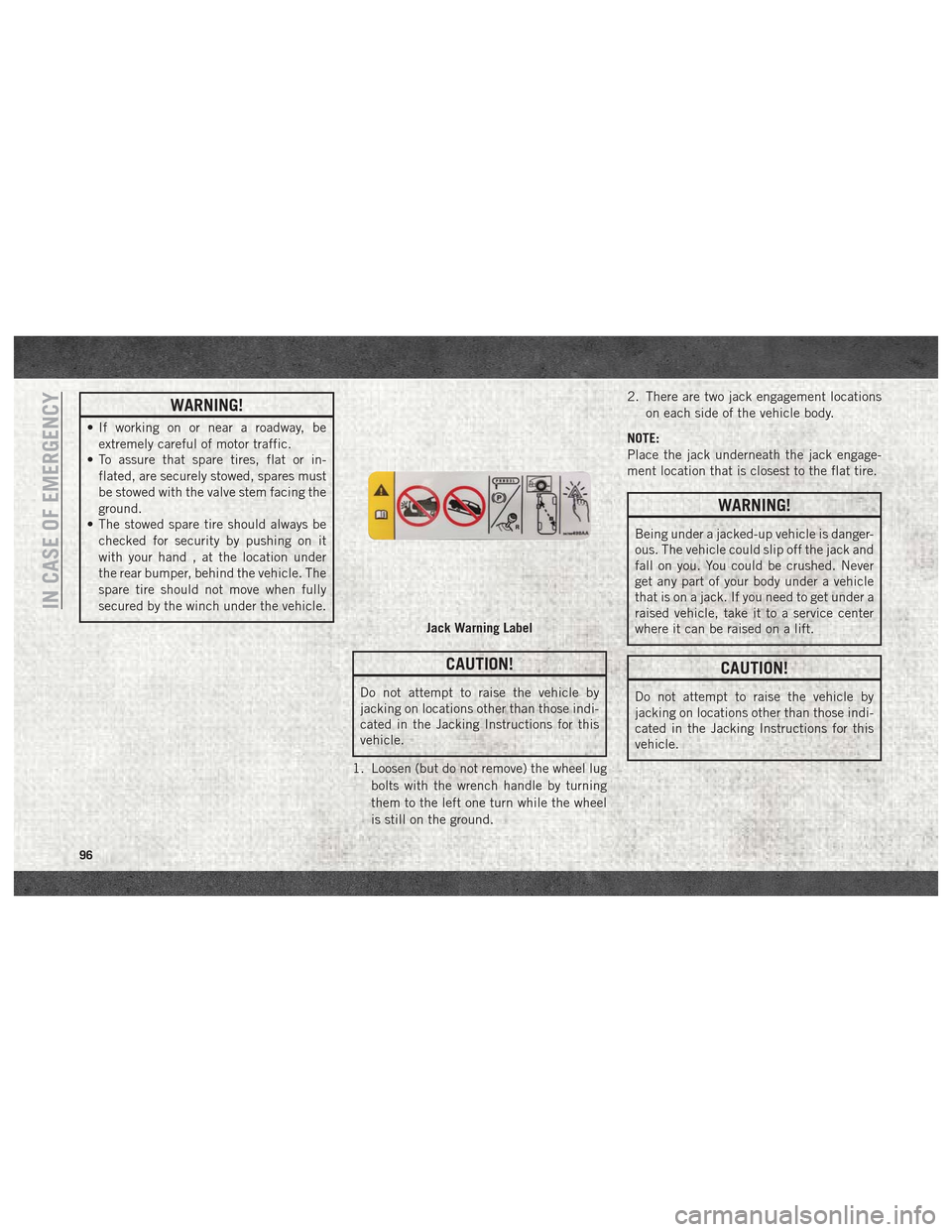
Jack Warning Label
IN CASE OF EMERGENCY
96
Page 99 of 180
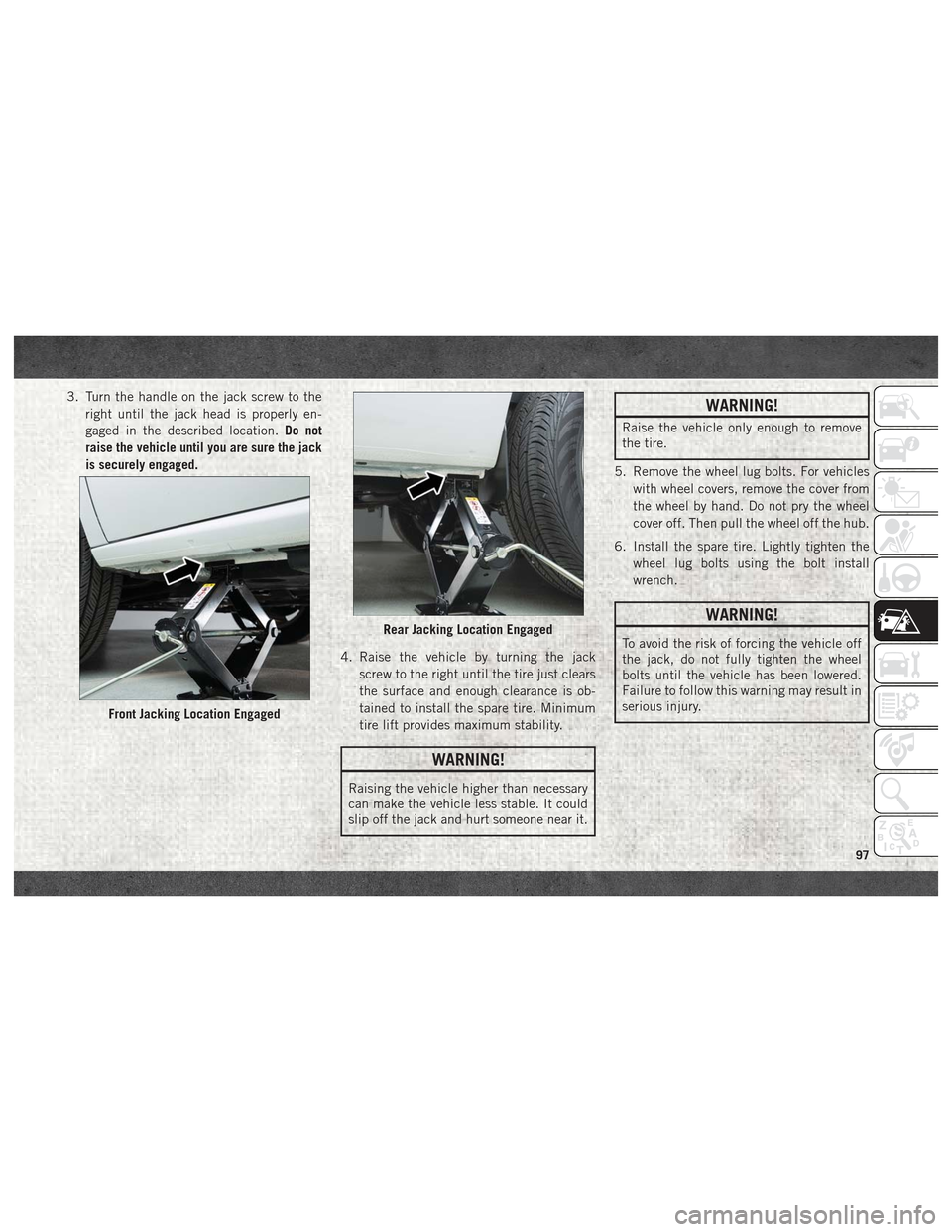
3. Turn the handle on the jack screw to theright until the jack head is properly en-
gaged in the described location. Do not
raise the vehicle until you are sure the jack
is securely engaged.
4. Raise the vehicle by turning the jackscrew to the right until the tire just clears
the surface and enough clearance is ob-
tained to install the spare tire. Minimum
tire lift provides maximum stability.
WARNING!
Raising the vehicle higher than necessary
can make the vehicle less stable. It could
slip off the jack and hurt someone near it.
WARNING!
Raise the vehicle only enough to remove
the tire.
5. Remove the wheel lug bolts. For vehicles with wheel covers, remove the cover from
the wheel by hand. Do not pry the wheel
cover off. Then pull the wheel off the hub.
6. Install the spare tire. Lightly tighten the wheel lug bolts using the bolt install
wrench.
WARNING!
To avoid the risk of forcing the vehicle off
the jack, do not fully tighten the wheel
bolts until the vehicle has been lowered.
Failure to follow this warning may result in
serious injury.
Front Jacking Location Engaged
Rear Jacking Location Engaged
97
Page 100 of 180
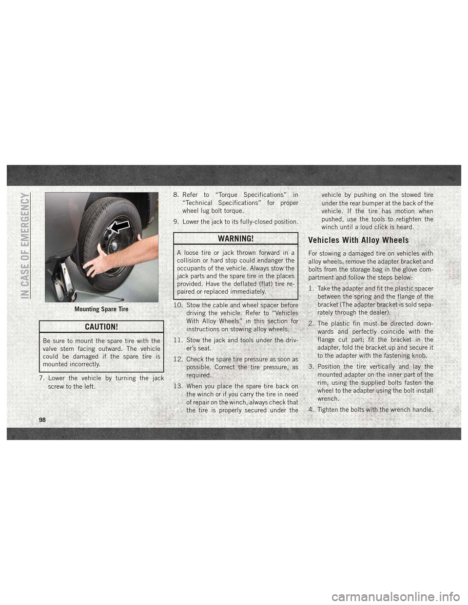
CAUTION!
Be sure to mount the spare tire with the
valve stem facing outward. The vehicle
could be damaged if the spare tire is
mounted incorrectly.
7. Lower the vehicle by turning the jack screw to the left. 8. Refer to “Torque Specifications” in
“Technical Specifications” for proper
wheel lug bolt torque.
9. Lower the jack to its fully-closed position.
WARNING!
A loose tire or jack thrown forward in a
collision or hard stop could endanger the
occupants of the vehicle. Always stow the
jack parts and the spare tire in the places
provided. Have the deflated (flat) tire re-
paired or replaced immediately.
10. Stow the cable and wheel spacer before driving the vehicle. Refer to “Vehicles
With Alloy Wheels” in this section for
instructions on stowing alloy wheels.
11. Stow the jack and tools under the driv- er’s seat.
12. Check the spare tire pressure as soon as possible. Correct the tire pressure, as
required.
13. When you place the spare tire back on the winch or if you carry the tire in need
of repair on the winch, always check that
the tire is properly secured under the vehicle by pushing on the stowed tire
under the rear bumper at the back of the
vehicle. If the tire has motion when
pushed, use the tools to retighten the
winch until a loud click is heard.
Vehicles With Alloy Wheels
For stowing a damaged tire on vehicles with
alloy wheels, remove the adapter bracket and
bolts from the storage bag in the glove com-
partment and follow the steps below:
1. Take the adapter and fit the plastic spacer
between the spring and the flange of the
bracket (The adapter bracket is sold sepa-
rately through the dealer).
2. The plastic fin must be directed down- wards and perfectly coincide with the
flange cut part; fit the bracket in the
adapter, fold the bracket up and secure it
to the adapter with the fastening knob.
3. Position the tire vertically and lay the mounted adapter on the inner part of the
rim, using the supplied bolts fasten the
wheel to the adapter using the bolt install
wrench.
4. Tighten the bolts with the wrench handle.
Mounting Spare Tire
IN CASE OF EMERGENCY
98