mirror Ram ProMaster City 2018 User Guide
[x] Cancel search | Manufacturer: RAM, Model Year: 2018, Model line: ProMaster City, Model: Ram ProMaster City 2018Pages: 180, PDF Size: 7.52 MB
Page 4 of 180
HOW TO USE THIS MANUAL
Essential Information
Each time direction instructions (left/right or
forwards/backwards) about the vehicle are
given, these must be intended as regarding
an occupant in the driver's seat. Special
cases not complying with this rule will be
properly specified in the text.
The figures in this User Guide are provided by
way of example only: this might imply that
some details of the image do not correspond
to the actual arrangement of your vehicle.
In addition, the User Guide has been con-
ceived considering vehicles with steering
wheel on the left side; it is therefore possiblethat on vehicles with steering wheel on the
right side, the position or construction of
some controls is not exactly mirror-like with
respect to the figure.
To identify the chapter with the information
needed you can consult the index at the end
of this User Guide.
Chapters can be rapidly identified with dedi-
cated graphic tabs, at the side of each odd
page. A few pages further there is a key for
getting to know the chapter order and the
relevant symbols in the tabs. There is anyway
a textual indication of the current chapter at
the side of each even page.
Symbols
Some vehicle components have colored la-
bels whose symbols indicate precautions to
be observed when using this component.
WARNINGS AND CAUTIONS
While reading this User Guide you will find a
series of WARNINGS to be followed to pre-
vent incorrect use of components which
could cause accidents or injuries.
There are also CAUTIONS that must be fol-
lowed to prevent against procedures that
could result in damage to your vehicle.INTRODUCTION
2
Page 22 of 180
CLIMATE CONTROLS
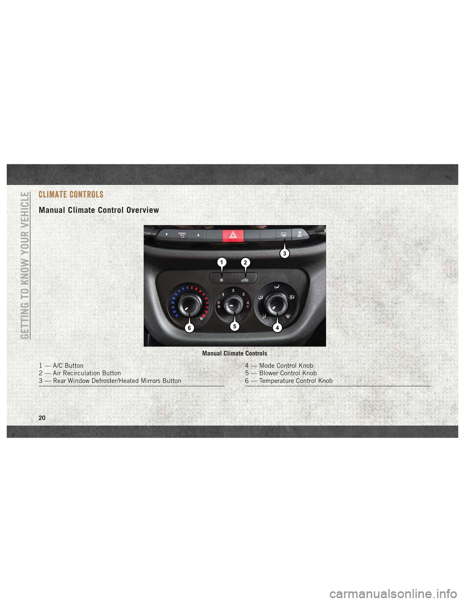
Manual Climate Control Overview
Manual Climate Controls
1 — A/C Button
2 — Air Recirculation Button
3 — Rear Window Defroster/Heated Mirrors Button4 — Mode Control Knob
5 — Blower Control Knob
6 — Temperature Control Knob
GETTING TO KNOW YOUR VEHICLE
20
Page 92 of 180
CavityMaxi Fuse Mini Fuse Description
F07 50 Amp Red –Radiator Fan - High Speed
F08 40 Amp Orange –Blower Motor
F10 –15 Amp BlueHorn
F11 –10 Amp RedSecondary Loads ECM
F14 –15 Amp BlueHigh Beam
F16 –5 Amp TanECM and Transmission Shifter
F17 –25 Amp ClearECM Power Loads
F18 –5 Amp TanECM Load, Main Relay
F19 –7.5 Amp Brown Air Conditioning
F20 –30 Amp Green Rear Defroster
F21 –5 Amp TanKey Unlock
F22 –10 Amp RedPrimary ECM Loads
F23 –20 Amp Yellow BSM System
F24 –5 Amp TanBSM System, Positive Key and Steering Angle Sensor
F30 –15 Amp Blue2nd Instrument Panel Power Outlet
F83 20 Amp Yellow –Fuel Pump
F84 –15 Amp BlueAT Module
F85 –15 Amp BlueRear Power Outlet 12V
F86 –15 Amp BlueIP Power Outlet 12V
F87 –5 Amp TanIBS
F88 –7.5 Amp Brown External Mirror Defrost
IN CASE OF EMERGENCY
90
Page 93 of 180
Interior Fuses
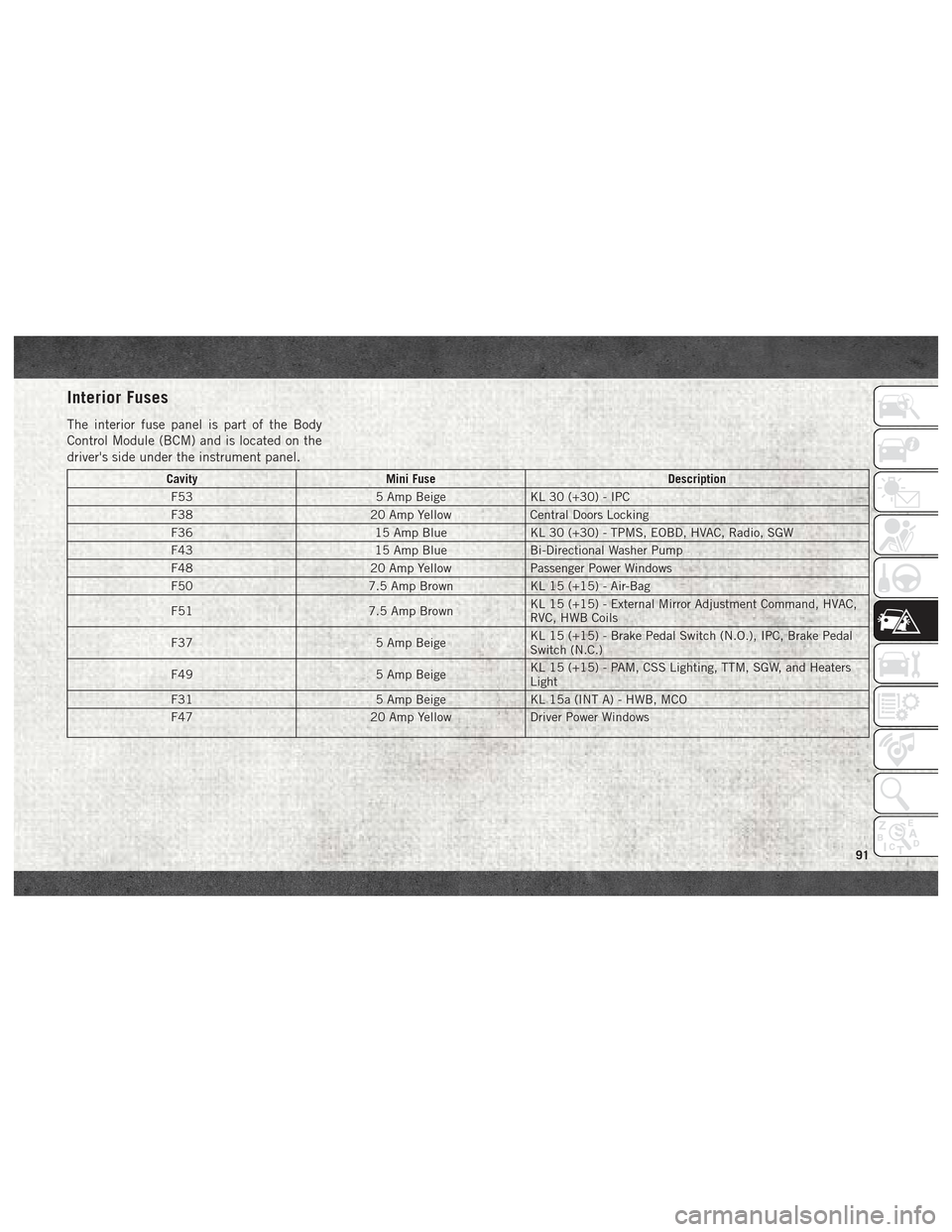
The interior fuse panel is part of the Body
Control Module (BCM) and is located on the
driver's side under the instrument panel.
CavityMini Fuse Description
F53 5 Amp BeigeKL 30 (+30) - IPC
F38 20 Amp YellowCentral Doors Locking
F36 15 Amp BlueKL 30 (+30) - TPMS, EOBD, HVAC, Radio, SGW
F43 15 Amp BlueBi-Directional Washer Pump
F48 20 Amp YellowPassenger Power Windows
F50 7.5 Amp BrownKL 15 (+15) - Air-Bag
F51 7.5 Amp BrownKL 15 (+15) - External Mirror Adjustment Command, HVAC,
RVC, HWB Coils
F37 5 Amp BeigeKL 15 (+15) - Brake Pedal Switch (N.O.), IPC, Brake Pedal
Switch (N.C.)
F49 5 Amp BeigeKL 15 (+15) - PAM, CSS Lighting, TTM, SGW, and Heaters
Light
F31 5 Amp BeigeKL 15a (INT A) - HWB, MCO
F47 20 Amp YellowDriver Power Windows
91
Page 161 of 180
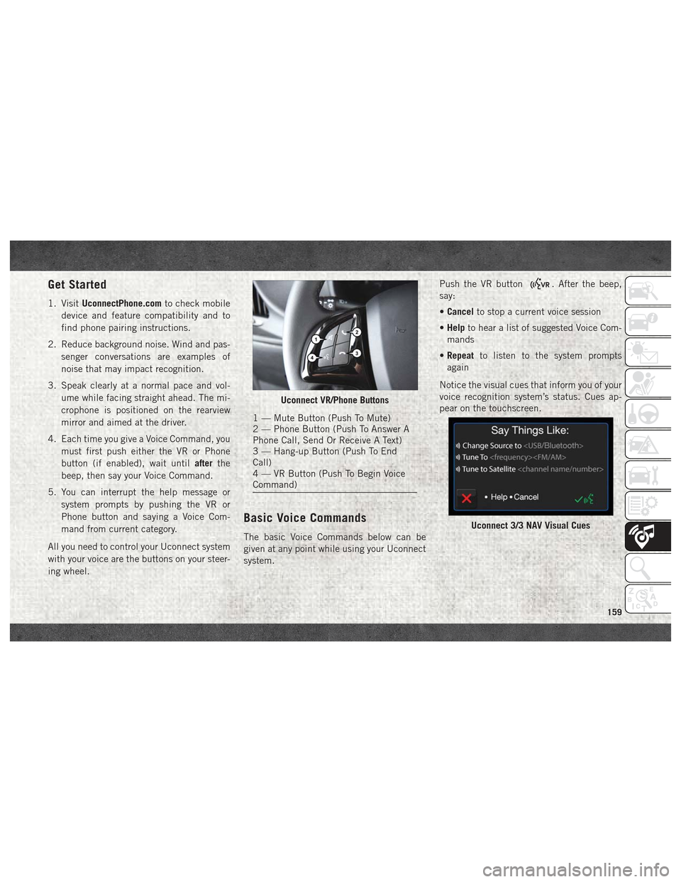
Get Started
1. VisitUconnectPhone.com to check mobile
device and feature compatibility and to
find phone pairing instructions.
2. Reduce background noise. Wind and pas- senger conversations are examples of
noise that may impact recognition.
3. Speak clearly at a normal pace and vol- ume while facing straight ahead. The mi-
crophone is positioned on the rearview
mirror and aimed at the driver.
4. Each time you give a Voice Command, you must first push either the VR or Phone
button (if enabled), wait until afterthe
beep, then say your Voice Command.
5. You can interrupt the help message or system prompts by pushing the VR or
Phone button and saying a Voice Com-
mand from current category.
All you need to control your Uconnect system
with your voice are the buttons on your steer-
ing wheel.
Basic Voice Commands
The basic Voice Commands below can be
given at any point while using your Uconnect
system. Push the VR button
. After the beep,
say:
• Cancel to stop a current voice session
• Help to hear a list of suggested Voice Com-
mands
• Repeat to listen to the system prompts
again
Notice the visual cues that inform you of your
voice recognition system’s status. Cues ap-
pear on the touchscreen.
Uconnect VR/Phone Buttons
1 — Mute Button (Push To Mute)
2 — Phone Button (Push To Answer A
Phone Call, Send Or Receive A Text)
3 — Hang-up Button (Push To End
Call)
4 — VR Button (Push To Begin Voice
Command)
Uconnect 3/3 NAV Visual Cues
159