Ram ProMaster City 2019 Owner's Manual
ProMaster City 2019
Ram
Ram
https://www.carmanualsonline.info/img/34/12517/w960_12517-0.png
Ram ProMaster City 2019 Owner's Manual
Trending: radio antenna, clock, ignition, gas mileage, oil filter, fuel additives, oil type
Page 201 of 348
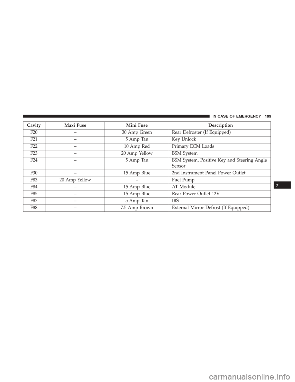
CavityMaxi Fuse Mini Fuse Description
F20 – 30 Amp Green Rear Defroster (If Equipped)
F21 – 5 Amp TanKey Unlock
F22 – 10 Amp Red Primary ECM Loads
F23 – 20 Amp Yellow BSM System
F24 – 5 Amp TanBSM System, Positive Key and Steering Angle
Sensor
F30 – 15 Amp Blue 2nd Instrument Panel Power Outlet
F83 20 Amp Yellow –Fuel Pump
F84 – 15 Amp Blue AT Module
F85 – 15 Amp Blue Rear Power Outlet 12V
F87 – 5 Amp TanIBS
F88 – 7.5 Amp Brown External Mirror Defrost (If Equipped)
7
IN CASE OF EMERGENCY 199
Page 202 of 348
Interior Fuses
The interior fuse panel is part of the Body Control Module
(BCM) and is located on the driver’s side under the
instrument panel.
Fuse Panel Cover
200 IN CASE OF EMERGENCY
Page 203 of 348
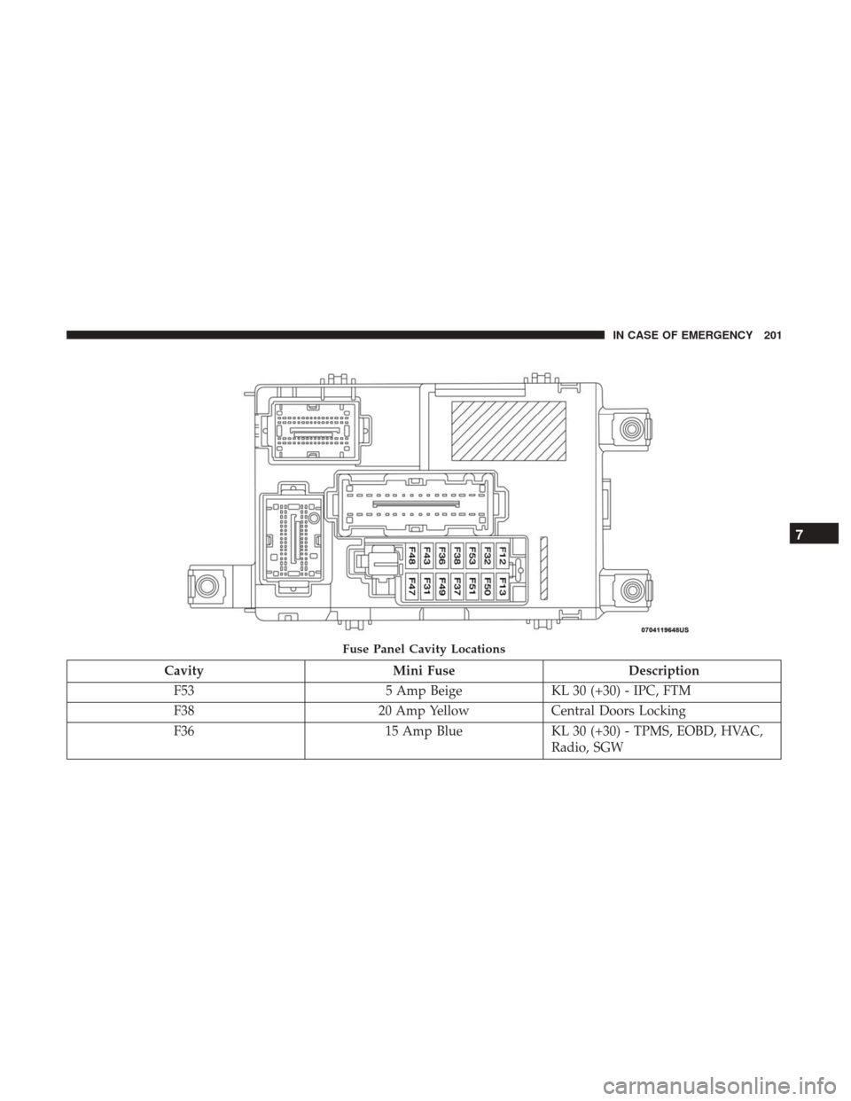
CavityMini Fuse Description
F53 5 Amp BeigeKL 30 (+30) - IPC, FTM
F38 20 Amp YellowCentral Doors Locking
F36 15 Amp BlueKL 30 (+30) - TPMS, EOBD, HVAC,
Radio, SGW
Fuse Panel Cavity Locations
7
IN CASE OF EMERGENCY 201
Page 204 of 348
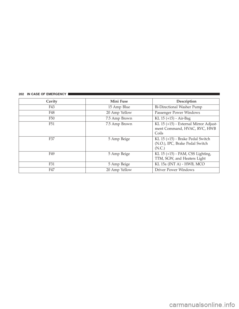
CavityMini Fuse Description
F43 15 Amp BlueBi-Directional Washer Pump
F48 20 Amp YellowPassenger Power Windows
F50 7.5 Amp BrownKL 15 (+15) - Air-Bag
F51 7.5 Amp BrownKL 15 (+15) - External Mirror Adjust-
ment Command, HVAC, RVC, HWB
Coils
F37 5 Amp BeigeKL 15 (+15) - Brake Pedal Switch
(N.O.), IPC, Brake Pedal Switch
(N.C.)
F49 5 Amp BeigeKL 15 (+15) - PAM, CSS Lighting,
TTM, SGW, and Heaters Light
F31 5 Amp BeigeKL 15a (INT A) - HWB, MCO
F47 20 Amp YellowDriver Power Windows
202 IN CASE OF EMERGENCY
Page 205 of 348
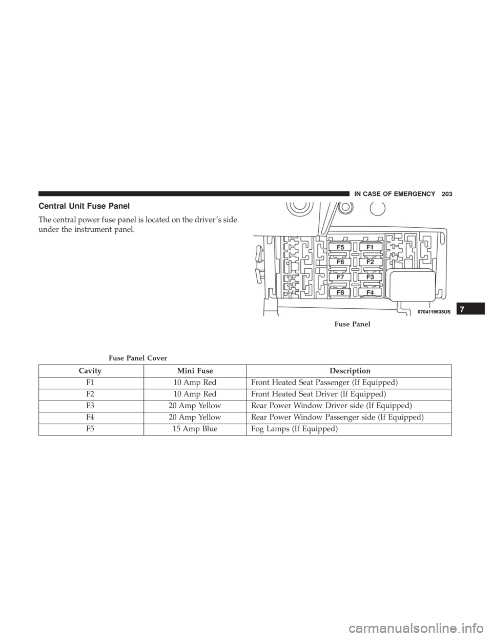
Central Unit Fuse Panel
The central power fuse panel is located on the driver ’s side
under the instrument panel.
CavityMini Fuse Description
F1 10 Amp Red Front Heated Seat Passenger (If Equipped)
F2 10 Amp Red Front Heated Seat Driver (If Equipped)
F3 20 Amp Yellow Rear Power Window Driver side (If Equipped)
F4 20 Amp Yellow Rear Power Window Passenger side (If Equipped)
F5 15 Amp Blue Fog Lamps (If Equipped)
Fuse Panel Cover
Fuse Panel
7
IN CASE OF EMERGENCY 203
Page 206 of 348
JACKING AND TIRE CHANGING
WARNING!
•Do not attempt to change a tire on the side of the
vehicle close to moving traffic. Pull far enough off
the road to avoid the danger of being hit when
operating the jack or changing the wheel.
• Being under a jacked-up vehicle is dangerous. The
vehicle could slip off the jack and fall on you. You
could be crushed. Never put any part of your body
under a vehicle that is on a jack. If you need to get
under a raised vehicle, take it to a service center
where it can be raised on a lift.
• Never start or run the engine while the vehicle is on
a jack.
• The jack is designed to be used as a tool for changing
tires only. The jack should not be used to lift the
vehicle for service purposes. The vehicle should be
jacked on a firm level surface only. Avoid ice or
slippery areas.
Jack Location
The jack and tools are stowed under the driver ’s front seat.
Jack/Tools Location
204 IN CASE OF EMERGENCY
Page 207 of 348
Removing The Spare Tire
1. Remove the spare tire before attempting to jack up thevehicle. Attach the wrench handle to the winch exten-
sion. 2. To access the winch mechanism open the rear doors of
the vehicle to expose the winch mechanism access cover.
Remove the access cover and install the winch extension
into the winch mechanism.
Jack Tools
1 — Wrench Handle
2 — Winch Extension
3 — Emergency Screwdriver
4 — Bolt Install Wrench
5 — Wheel Chock
6 — Jack
Winch Location
7
IN CASE OF EMERGENCY 205
Page 208 of 348
3. Rotate the wheel wrench handle counterclockwise untilthe spare tire is on the ground with enough cable slack
to allow you to pull it out from under the vehicle.
NOTE: The winch mechanism is designed for use with the
winch extension only. Use of an air wrench or other power
tools is not recommended and can damage the winch. 4. Pull the spare tire out from under the vehicle to gain
access to the spare tire retainer.
Jack Tools
1 — Winch Extension
2 — Wrench HandleSpare Tire
206 IN CASE OF EMERGENCY
Page 209 of 348
5. Remove the retainer nut prior to removing the retainerfrom the wheel. 6. Lift the spare tire with one hand to give clearance to tilt
the retainer at the end of the cable.
Retainer NutLifting Spare Tire
7
IN CASE OF EMERGENCY 207
Page 210 of 348
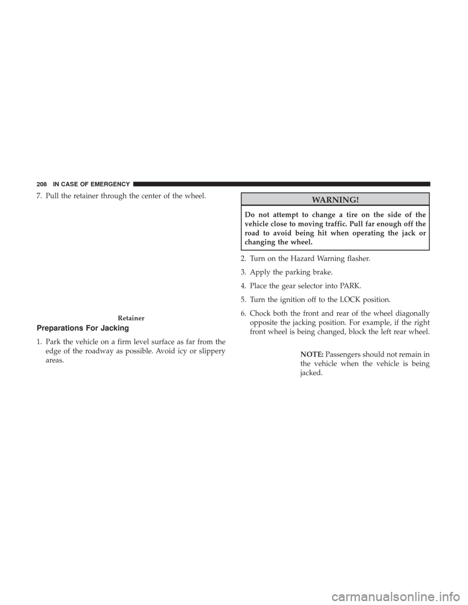
7. Pull the retainer through the center of the wheel.
Preparations For Jacking
1. Park the vehicle on a firm level surface as far from theedge of the roadway as possible. Avoid icy or slippery
areas.
WARNING!
Do not attempt to change a tire on the side of the
vehicle close to moving traffic. Pull far enough off the
road to avoid being hit when operating the jack or
changing the wheel.
2. Turn on the Hazard Warning flasher.
3. Apply the parking brake.
4. Place the gear selector into PARK.
5. Turn the ignition off to the LOCK position.
6. Chock both the front and rear of the wheel diagonally opposite the jacking position. For example, if the right
front wheel is being changed, block the left rear wheel.
NOTE:Passengers should not remain in
the vehicle when the vehicle is being
jacked.
Retainer
208 IN CASE OF EMERGENCY
Trending: boot, octane, climate settings, fuel tank removal, coolant, fuse panel, set clock
