steering Ram ProMaster City 2020 User Guide
[x] Cancel search | Manufacturer: RAM, Model Year: 2020, Model line: ProMaster City, Model: Ram ProMaster City 2020Pages: 350, PDF Size: 13.27 MB
Page 55 of 350

52 GETTING TO KNOW YOUR VEHICLE
Windshield Washers
Pull the windshield wiper/washer lever toward the steering
wheel to activate the washers. The wipers will activate auto-
matically for three cycles after the lever is released. Manual High Speed/Mist
Push the lever upward from the off position. The wipers will
operate at high speed to clear off road mist or spray from a
passing vehicle. This operation will continue until the lever
is released. When the lever is released, the wipers will return
to the off position and automatically shut off.
Rear Wiper Operation — If Equipped
Rear Windshield Wiper Operation
Rotate the windshield wiper lever center ring upwards to
operate the rear window wiper as follows:
• In intermittent mode when the front window wiper is not
operating
• In synchronous mode (at half the speed of the front window wiper) when the front window wiper is operating
• In continuous mode while vehicle is in REVERSE
With the windshield wipers on, and REVERSE gear engaged,
rear window wiping will be continuous in the same way.
CAUTION!
• Turn the windshield wipers off when driving through an automatic car wash. Damage to the windshield
wipers may result if the wiper control is left in any
position other than off.
• In cold weather, always turn off the wiper switch and allow the wipers to return to the park position before
turning off the engine. If the wiper switch is left on and
the wipers freeze to the windshield, damage to the
wiper motor may occur when the vehicle is restarted.
• Always remove any buildup of snow that prevents the windshield wiper blades from returning to the off posi -
tion. If the windshield wiper control is turned off and
the blades cannot return to the off position, damage to
the wiper motor may occur.
2020_RAM_PROMASTER_CITY_OM_USA=GUID-7B6A7FCA-79B0-423F-95C5-ED2A949C3D13=1=en=.book Page 52
Page 81 of 350

78 GETTING TO KNOW YOUR INSTRUMENT PANEL
The menu items described below are an example of what can
be found in the vehicle's menu:
• Dimmer
• Speed Beep
• Trip A / B (options are selectable through the steeringwheel stalk)
• Buzzer Volume
The system allows the driver to select information by
pushing the following buttons mounted on the instrument
panel to the right of the steering column: Instrument Cluster Display Control Buttons
• MENU Button
Push and release the MENU button for a time longer than
one second to access/select the information screens or
submenu screens of a main menu item. Push and hold the
MENU button for two seconds to reset displayed/selected
features that can be reset.
2020_RAM_PROMASTER_CITY_OM_USA=GUID-7B6A7FCA-79B0-423F-95C5-ED2A949C3D13=1=en=.book Page 78
Page 85 of 350

82 GETTING TO KNOW YOUR INSTRUMENT PANEL
Seat Belt Buzzer
Only shows in the instrument cluster display if the seat belt
reminder was previously deactivated by an authorized dealer.
NOTE:
This is a one-time occurrence to enable the acoustic signal.
Exit Menu
This is the last function that closes the cycle of settings listed
in the menu screen.
1. Pushing the MENU button briefly will return the display
to the standard screen without storing.
2. Push the down arrow button to return to the first menu
item on the display.
TRIP COMPUTER
The Trip Computer is located in the instrument cluster. It
features a driver-interactive display (displays information
such as trip information, range, fuel consumption, average
speed, and travel time).
NOTE:
The Uconnect System also has a Trip Computer display and
menus to customize the information displayed in the cluster. For further information, refer to “Uconnect Settings” in
“Multimedia”.
Trip Button
The
TRIP button, located on the right steering column stalk,
can be used to display and to reset the previously described
values.
• A short button push displays the different values.
• A long button push resets the system and then starts a new trip.
New Trip
To reset:
• Push and hold the TRIP button to reset the system manually.
• When the “Trip distance” reaches 99999.9 miles or kilome -
ters or when the “Travel time” reaches 999.59 (999 hours
and 59 minutes), the system is reset automatically.
• Disconnecting/Reconnecting the battery resets the system.
NOTE:
If the reset operation occurs in the presence of the screens
concerning Trip A or Trip B, only the information associated
with Trip A or Trip B functions will be reset.
2020_RAM_PROMASTER_CITY_OM_USA=GUID-7B6A7FCA-79B0-423F-95C5-ED2A949C3D13=1=en=.book Page 82
Page 92 of 350

GETTING TO KNOW YOUR INSTRUMENT PANEL 89
Low Fuel Warning LightWhen the fuel level reaches approximately 2–3 gal
(9–11 L) this light will turn on, and remain on until
fuel is added.
Generic Warning Light The Generic Warning Light will illuminate if any of
the following conditions occur: Engine Oil Pressure
Sensor Failure, External Light Failure, Parking
Sensor Failure, Fuel Cut-Off Fail/Intervention, Generic
Failure on Trailer, or Air Bag telltale recovery.
The telltale will blink in case of an Air Bag Warning Light
Failure. Contact an authorized dealer immediately for
service.
Tire Pressure Monitoring System (TPMS) Warning Light
The warning light switches on and a message is
displayed to indicate that the tire pressure is lower
than the recommended value and/or that slow pres -
sure loss is occurring. In these cases, optimal tire duration
and fuel consumption may not be guaranteed. Should one or more tires be in the condition mentioned
above, the display will show the indications corresponding
to each tire.
Each tire, including the spare (if provided), should be
checked monthly when cold and inflated to the inflation
pressure recommended by the vehicle manufacturer on the
vehicle placard or tire inflation pressure label. If your vehicle
has tires of a different size than the size indicated on the
vehicle placard or tire inflation pressure label, you should
determine the proper tire inflation pressure for those tires.
As an added safety feature, your vehicle has been equipped
with a Tire Pressure Monitoring System (TPMS) that illumi
-
nates a low tire pressure telltale when one or more of your
tires is significantly under-inflated. Accordingly, when the
low tire pressure telltale illuminates, you should stop and
check your tires as soon as possible, and inflate them to the
CAUTION!
Do not continue driving with one or more flat tires as
handling may be compromised. Stop the vehicle,
avoiding sharp braking and steering. If a tire puncture
occurs, repair immediately using the dedicated tire
repair kit and contact an authorized dealer as soon as
possible.
3
2020_RAM_PROMASTER_CITY_OM_USA=GUID-7B6A7FCA-79B0-423F-95C5-ED2A949C3D13=1=en=.book Page 89
Page 100 of 350

97
(Continued)
SAFETY
SAFETY FEATURES
Four-Wheel Anti-Lock Brake System (ABS)
The Four-Wheel Anti-Lock Brake System (ABS) is designed
to aid the driver in maintaining vehicle control under
adverse braking conditions. The system operates with a
separate computer to modulate hydraulic pressure, to
prevent wheel lock-up and to help avoid skidding on
slippery surfaces.
The system's pump motor runs during an ABS stop to
provide regulated hydraulic pressure. The pump motor
makes a low humming noise during operation, which is
normal.
The ABS includes an amber ABS Warning Light. When the
light is illuminated, the ABS is not functioning. The system
reverts to standard non-anti-lock brakes. Turning the igni-
tion OFF and ON again may reset the ABS if the fault
detected was only momentary.
WARNING!
• The ABS contains sophisticated electronic equipment that may be susceptible to interference caused by
improperly installed or high output radio transmitting
equipment. This interference can cause possible loss of
anti-lock braking capability. Installation of such equip -
ment should be performed by qualified professionals.
• Pumping of the Anti-Lock Brakes will diminish their effectiveness and may lead to a collision. Pumping
makes the stopping distance longer. Just press firmly
on your brake pedal when you need to slow down or
stop.
• The ABS cannot prevent the natural laws of physics from acting on the vehicle, nor can it increase braking
or steering efficiency beyond that afforded by the
condition of the vehicle brakes and tires or the traction
afforded.
4
2020_RAM_PROMASTER_CITY_OM_USA=GUID-7B6A7FCA-79B0-423F-95C5-ED2A949C3D13=1=en=.book Page 97
Page 102 of 350

SAFETY 99
(Continued)
Electronic Stability Control (ESC)
Electronic Stability Control (ESC) enhances directional
control and stability of the vehicle under various driving
conditions. ESC corrects for over/under steering of the
vehicle by applying the brake of the appropriate wheel to
assist in counteracting the over/under steer condition.
Engine power may also be reduced to help the vehicle main-
tain the desired path.
ESC uses sensors in the vehicle to determine the vehicle path
intended by the driver and compares it to the actual path of
the vehicle. When the actual path does not match the intended path, ESC applies the brake of the appropriate
wheel to assist in counteracting the oversteer or understeer
condition.
• Oversteer - when the vehicle is turning more than appro
-
priate for the steering wheel position.
• Understeer - when the vehicle is turning less than appro -
priate for the steering wheel position.
WARNING!
The Brake Assist System (BAS) cannot prevent the
natural laws of physics from acting on the vehicle, nor
can it increase the traction afforded by prevailing road
conditions. BAS cannot prevent collisions, including
those resulting from excessive speed in turns, driving on
very slippery surfaces, or hydroplaning. The capabilities
of a BAS-equipped vehicle must never be exploited in a
reckless or dangerous manner, which could jeopardize
the user's safety or the safety of others.
WARNING!
• Electronic Stability Control (ESC) cannot prevent the natural laws of physics from acting on the vehicle, nor
can it increase the traction afforded by prevailing road
conditions. ESC cannot prevent accidents, including
those resulting from excessive speed in turns, driving
on very slippery surfaces, or hydroplaning. ESC also
cannot prevent accidents resulting from loss of vehicle
control due to inappropriate driver input for the condi -
tions. Only a safe, attentive, and skillful driver can
prevent accidents. The capabilities of an ESC equipped
vehicle must never be exploited in a reckless or
dangerous manner which could jeopardize the user’s
safety or the safety of others.4
2020_RAM_PROMASTER_CITY_OM_USA=GUID-7B6A7FCA-79B0-423F-95C5-ED2A949C3D13=1=en=.book Page 99
Page 103 of 350

100 SAFETY
ESC Activation/Malfunction Indicator Light And ESC
OFF Indicator Light The ESC Activation/Malfunction Indicator Light in
the instrument cluster will come on when the igni -
tion switch is turned to the MAR (ON/RUN) posi -
tion for four seconds. If the ESC Activation/Malfunction
Indicator Light comes on continuously with the engine
running, a malfunction has been detected in the ESC system.
If this light remains on after several ignition cycles, and the vehicle has been driven several miles (km) at speeds greater
than 30 mph (48 km/h), see an authorized dealer as soon as
possible to have the problem diagnosed and corrected.
The ESC Activation/Malfunction Indicator Light (located in
the instrument cluster) starts to flash as soon as the tires lose
traction and the ESC system becomes active. The ESC Activa
-
tion/Malfunction Indicator Light also flashes when TCS is
active. If the ESC Activation/Malfunction Indicator Light
begins to flash during acceleration, ease up on the accelerator
and apply as little throttle as possible. Be sure to adapt your
speed and driving to the prevailing road conditions.
NOTE:
• The ESC Activation/Malfunction Indicator Light and the ESC OFF Indicator Light come on momentarily each time
the ignition switch is turned ON.
• Each time the ignition is turned ON, the ESC system will be ON even if it was turned off previously.
The ESC OFF Indicator Light indicates the Electronic
Stability Control (ESC) is partially off.
• Vehicle modifications, or failure to properly maintain
your vehicle, may change the handling characteristics
of your vehicle, and may negatively affect the perfor -
mance of the ESC system. Changes to the steering
system, suspension, braking system, tire type and size
or wheel size may adversely affect ESC performance.
Improperly inflated and unevenly worn tires may also
degrade ESC performance. Any vehicle modification or
poor vehicle maintenance that reduces the effective -
ness of the ESC system can increase the risk of loss of
vehicle control, vehicle rollover, personal injury and
death.
WARNING! (Continued)
2020_RAM_PROMASTER_CITY_OM_USA=GUID-7B6A7FCA-79B0-423F-95C5-ED2A949C3D13=1=en=.book Page 100
Page 104 of 350

SAFETY 101
Electronic Roll Mitigation (ERM)
Electronic Roll Mitigation (ERM) anticipates the potential for
wheel lift by monitoring the driver’s steering wheel input
and the speed of the vehicle. When ERM determines that the
rate of change of the steering wheel angle and vehicle’s
speed are sufficient to potentially cause wheel lift, it then
applies the appropriate brake and may also reduce engine
power to lessen the chance that wheel lift will occur.
ERM can only reduce the chance of wheel lift occurring
during severe or evasive driving maneuvers; it cannot
prevent wheel lift due to other factors, such as road
conditions, leaving the roadway, or striking objects or other
vehicles.Hill Start Assist (HSA)
Hill Start Assist (HSA) is designed to assist the driver when
starting a vehicle from a stop on a hill. HSA will maintain the
level of brake pressure the driver applied for a short period
of time after the driver takes their foot off of the brake pedal.
If the driver does not apply the throttle during this short
period of time, the system will release brake pressure and the
vehicle will roll down the hill. The system will release brake
pressure in proportion to the amount of throttle applied as
the vehicle starts to move in the intended direction of travel.
HSA Activation Criteria
The following criteria must be met in order for HSA to
activate:
• The vehicle must be stopped.
• The vehicle must be on a 5% (approximate) grade or
greater hill.
• Gear selection matches vehicle uphill direction (i.e., vehicle facing uphill is in forward gear; vehicle backing
uphill is in REVERSE (R) gear).
HSA will work in REVERSE and all forward gears when the
activation criteria have been met. The system will not activate if
the vehicle is placed in NEUTRAL (N) or PARK (P).
WARNING!
Many factors, such as vehicle loading, road conditions
and driving conditions, influence the chance that wheel
lift or rollover may occur. ERM cannot prevent all wheel
lift or roll overs, especially those that involve leaving the
roadway or striking objects or other vehicles. The
capabilities of an ERM-equipped vehicle must never be
exploited in a reckless or dangerous manner which could
jeopardize the user's safety or the safety of others.
4
2020_RAM_PROMASTER_CITY_OM_USA=GUID-7B6A7FCA-79B0-423F-95C5-ED2A949C3D13=1=en=.book Page 101
Page 123 of 350

120 SAFETY
How To Disengage The Automatic Locking Mode
Unbuckle the combination lap/shoulder belt and allow it to
retract completely to disengage the Automatic Locking
Mode and activate the vehicle sensitive (emergency) locking
mode.Supplemental Restraint Systems (SRS)
Some of the safety features described in this section may be
standard equipment on some models, or may be optional
equipment on others. If you are not sure, ask an authorized
dealer.
The air bag system must be ready to protect you in a colli-
sion. The Occupant Restraint Controller (ORC) monitors the
internal circuits and interconnecting wiring associated with
the electrical Air Bag System Components. Your vehicle may
be equipped with the following Air Bag System Compo -
nents:
Air Bag System Components
• Occupant Restraint Controller (ORC)
• Air Bag Warning Light
• Steering Wheel and Column
• Instrument Panel
• Knee Impact Bolsters
• Driver and Front Passenger Air Bags
• Seat Belt Buckle Switch
WARNING!
• The seat belt assembly must be replaced if the switch -
able Automatic Locking Retractor (ALR) feature or any
other seat belt function is not working properly when
checked according to the procedures in the Service
Manual.
• Failure to replace the seat belt assembly could increase the risk of injury in collisions.
• Do not use the Automatic Locking Mode to restrain occupants who are wearing the seat belt or children
who are using booster seats. The locked mode is only
used to install rear-facing or forward-facing child
restraints that have a harness for restraining the child.
2020_RAM_PROMASTER_CITY_OM_USA=GUID-7B6A7FCA-79B0-423F-95C5-ED2A949C3D13=1=en=.book Page 120
Page 125 of 350

122 SAFETY
(Continued)
Front Air Bags
This vehicle has front air bags and lap/shoulder belts for
both the driver and front passenger. The front air bags are a
supplement to the seat belt restraint systems. The driver
front air bag is mounted in the center of the steering wheel.
The passenger front air bag is mounted in the instrument
panel, above the glove compartment. The words “SRS
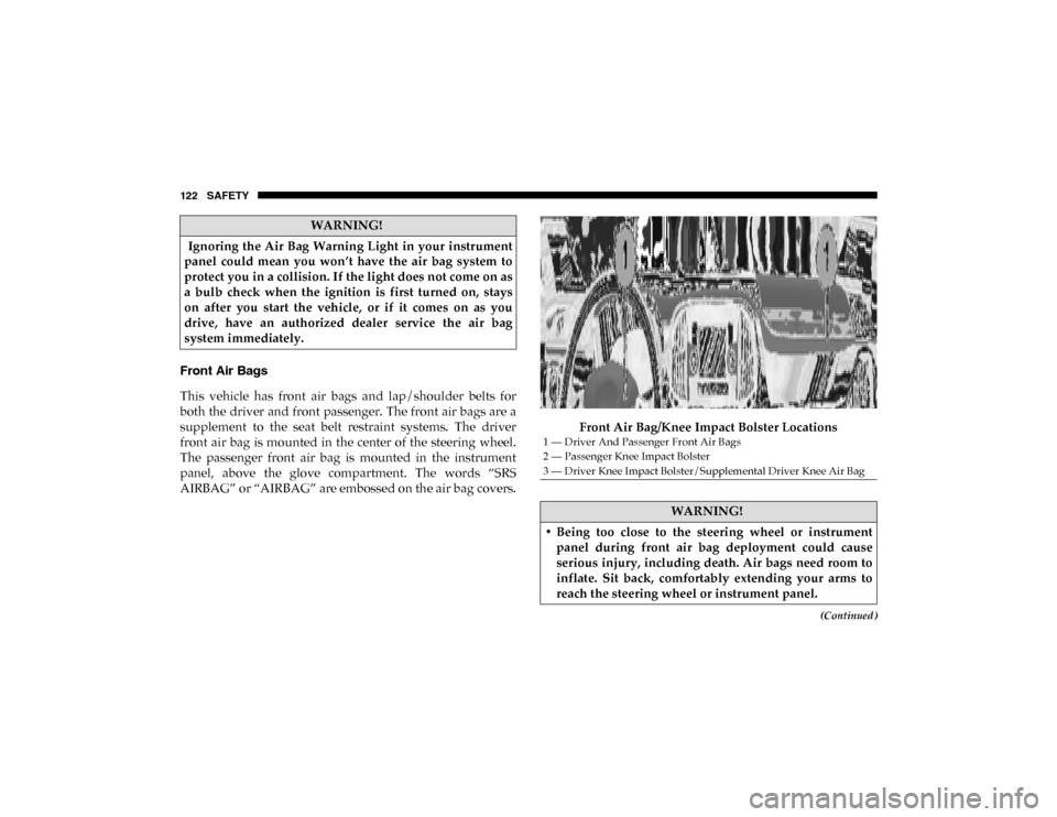
AIRBAG” or “AIRBAG” are embossed on the air bag covers.Front Air Bag/Knee Impact Bolster Locations
WARNING!
Ignoring the Air Bag Warning Light in your instrument
panel could mean you won’t have the air bag system to
protect you in a collision. If the light does not come on as
a bulb check when the ignition is first turned on, stays
on after you start the vehicle, or if it comes on as you
drive, have an authorized dealer service the air bag
system immediately.
1 — Driver And Passenger Front Air Bags
2 — Passenger Knee Impact Bolster
3 — Driver Knee Impact Bolster/Supplemental Driver Knee Air Bag
WARNING!
• Being too close to the steering wheel or instrument panel during front air bag deployment could cause
serious injury, including death. Air bags need room to
inflate. Sit back, comfortably extending your arms to
reach the steering wheel or instrument panel.
2020_RAM_PROMASTER_CITY_OM_USA=GUID-7B6A7FCA-79B0-423F-95C5-ED2A949C3D13=1=en=.book Page 122